Table of Contents
Advertisement
Quick Links
USER MANUAL
Standard Models
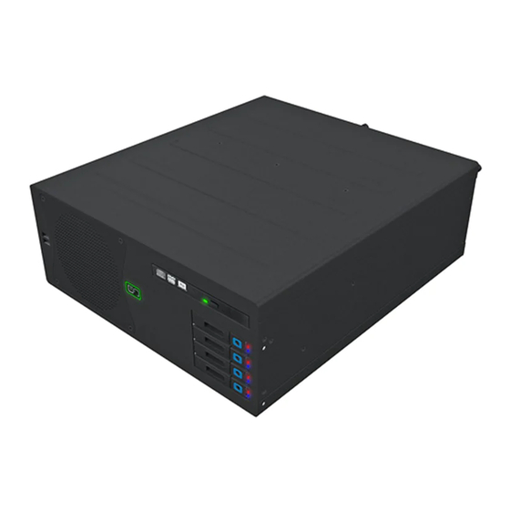
HT C02 - Compact Computer
Standard Models: HT C02Hx STC-yzz-wzzz
Entry Level Models: HT C02HI STC-yzz-wzzz
where x=CPU type, y=OS, w=Power Input (AC or DC), z=configuration
Updated: 08 Jul 2021
Created: 363
Please visit www.hattelandtechnology.com for the latest electronic version of this manual.
User Manual HT C02
Doc Id: INB10042-4 (Rev 13)
Approved: 6987
Entry Level Models
Advertisement
Table of Contents

Related Manuals for EMBRON HATTELAND TECHNOLOGY HT C02H STC Series


Summary of Contents for EMBRON HATTELAND TECHNOLOGY HT C02H STC Series
- Page 1 USER MANUAL Entry Level Models Standard Models HT C02 - Compact Computer Standard Models: HT C02Hx STC-yzz-wzzz Entry Level Models: HT C02HI STC-yzz-wzzz where x=CPU type, y=OS, w=Power Input (AC or DC), z=configuration User Manual HT C02 Updated: 08 Jul 2021 Doc Id: INB10042-4 (Rev 13) Created: 363 Approved: 6987...
- Page 2 Copyright © 2021 Hatteland Technology AS Eikeskogvegen 52, N-5570 Aksdal, Norway. All rights are reserved by Hatteland Technology AS. This information may not, in whole or in part, be copied, photocopied, reproduced, translated or reduced to any electronic medium or machine- readable form without the prior written consent of Hatteland Technology AS.
-
Page 3: Table Of Contents
Contents Contents ..................3 Contents of package ....................... 6 General ..................9 IEC62368 policy - Introduction ..................... 10 About this manual ........................11 About Hatteland Technology ....................11 www.hattelandtechnology.com ....................11 Contact Information .......................11 Computers introduction ......................12 Product Labels (Examples) ....................13 Serial Number and Operating System (OS) license label placement ...... - Page 4 Contents Specifications ................. 49 Specifications - HT C02Hx STC-yzz-wzzz ................50 Standard Models ......................50 Specifications - HT C02HI STC-yzz-wzzz ................51 Entry Level Models ......................51 Specifications Factory Options..........53 Specifications - COM Module RS-232 .................. 54 PCA100294-1 ........................54 Specifications - NMEA / IEC COM Module RS-422 / RS-485 ..........
- Page 5 Contents Appendixes ................79 BIOS - Hybrid Multi Monitor Configuration ................80 BIOS - On-board COM Ports Configuration ................. 82 BIOS - How to create RAID volume ..................85 SSD Selection Guide ......................89 Pinout Assignments ......................93 IEC62368 policy for Hatteland Technology products ............97 Trouble-shooting ........................
-
Page 6: Contents Of Package
Contents of package Accessories Box Contains: 1 x TP52/TC11-1.8M (AC only) 1 x TP11/TC11-1.8M (AC only) 1 x FCE17-E2W2SS-2N0 & 1 x L17DPPK09JSU (cover) (Only included for DC models) 1 x DVI-4 1 x 742 712 21 Ferrite 1 x Product Declaration 1 x Computer Checklist 1 x BurnInTest Certificate 1 x HT 00226 OPT-A1... - Page 7 Contents of package 1 pcs - Würth 742 712 21 This ferrite is required when using 100/110/115V AC voltage on the power supply (not required for 230V AC) to be fully compliant with type approvals. Review installation chapter for more information. Würth 742 712 21 (split, 10.5mm) Mounting brackets incl.
- Page 8 This page left intentionally blank...
-
Page 9: General
General... -
Page 10: Iec62368 Policy - Introduction
IEC62368 policy - Introduction Safety Instructions Please read and understand the material in the manual in its entirety before doing any installation/servicing/upgrades. Personnel who are allowed to do work on the unit is detailed in the “IEC62368 policy for Hatteland Technology product”... -
Page 11: About This Manual
Hatteland Technology AS About this manual The manual contains electrical, mechanical and input/output signal specifications. All specifications in this manual, due to manufacturing, new revisions and approvals, are subject to change without notice. However, the last updated and revision date of this manual are shown both on the frontpage and also in the “Revision History” chapter. This user manual is a standard/general manual that applies to all variations of its product family, i.e. -
Page 12: Computers Introduction
Computers 47,50 1,87 345,00 13,58 SIDE VIEW Computers introduction Hatteland Technology’s range of type-approved computers is designed to 8,70 0,34 14,50 0,57 173,00 6,81 173,00 6,81 22,00 0,87 perform in harsh environments while providing the performance and flexibility 5x M4 mounting holes you expect. -
Page 13: Product Labels (Examples)
Product Labels (Examples) Product Labels (Examples) Serial Number and Operating System (OS) license label placement Only present if the unit was delivered with factory installed Operating System (OS) such as Microsoft® Windows® Embedded Enterprise. The same Product Key is also printed on the “Product Declaration”... - Page 14 This page left intentionally blank...
-
Page 15: Installation
Installation... -
Page 16: Installation And Mounting Of Computers
General Installation Recommendations Installation and mounting of computers Units may be intended for various methods of installation or mounting (rack mounting, panel mounting, bracket mounting, ceiling/wall mounting); for details, please see the relevant mechanical drawings. Adequate ventilation is a necessary prerequisite for the life of the unit. The air inlet and outlet openings must definitely be kept clear;... -
Page 17: General Mounting Instructions
General Installation Recommendations General mounting instructions The useful life of the components of all Electronics Units generally decreases with increasing ambient temperature; it is therefore advisable to install such units in air-conditioned rooms. If there are no such facilities, these rooms must at least be dry, adequately ventilated and kept at a suitable temperature in order to prevent the formation of condensation inside the unit. -
Page 18: Ferrite
General Installation Recommendations Ferrite The ferrite prevents high frequency electrical noise (radio frequency interference) from exiting or entering the equipment. This ferrite is required when using 100/110/115V AC voltage on the power supply (not required for 230/240V AC) to be fully compliant with type approvals. The ferrite should be mounted (clipped in place on the cable) and located as close as possible to the connector piece that connects to the rear of computer. -
Page 19: Unit Upgrade Precaution Note
General Installation Recommendations CAUTION This unit contains electrostatic sensitive devices. Observe precautions for handling. Unit Upgrade Precaution Note Users which needs to open the unit to expose and reveal electronics, make sure that prior to touching / removing parts, proper ESD measurements must be taken! 1. -
Page 20: General Installation Recommendations
General Installation Recommendations Configuring DC power input housing connector Note: Only applicable for DC models! FIG 3 For installations that require DC power input, use the provided FIG 1 2-pin DC Power Input housing with internal cable screw terminal. It is recommended that thickness of cables are Minimum 20 AWG and Maximum 18 AWG. -
Page 21: Housing / Terminal Block Connector Overview
General Installation Recommendations Housing / Terminal Block Connector Overview Housing / Terminal Block connectors are available in different sizes (example 2-pin, 4-pin, 5-pin) which plug into the connector area of the unit. They are mounted by factory default and delivered with the unit. The housing / terminal block connectors have steering rails, which ensures that it can not be mounted wrong. - Page 22 General Installation Recommendations Configuring Housing / Terminal Block connectors Below is a brief illustration that might be useful during configuration and installation of such connectors. You will need suitable pre-configured cable(s) and tools to configure the connector(s) and cable(s) that are present in your installation environment.
-
Page 23: Cabinet Cover Removal
General Installation Recommendations Cabinet cover removal Note: Areas of interest are marked in this section with arrows in color. Please disconnect ALL cables from the computer unit before proceeding! Procedure applies for HT C02H, HT C02HI and HM C02HK models. 1: Unscrew 3 screws from top of cabinet. -
Page 24: Installing Pci / Pcie Card / Rework Pci Bracket Options - Notice
General Installation Recommendations Installing PCI / PCIe Card / Rework PCI Bracket Options - Notice All factory options are done in-house by our production facility prior to delivery. If you however need to install your own PCI/PCIe cards later and any of the PCI Bracket Options are already pre-installed, please review: “Physical Connections/ Added functionality through 4 x PCI Sized Metal Brackets”... -
Page 25: Pci / Pcie Card Removal / Replacement - Introduction
General Installation Recommendations PCI / PCIe Card removal / replacement - Introduction Note: Areas of interest are marked in this section with circles and arrows in color. Please disconnect ALL cables from the computer unit before proceeding! Procedure applies for HT C02H, HT C02HI and HM C02HK models. -
Page 26: Ht 00229Opt-A1 (Pci / Pcie Card Bracket, Removal & Replacement) Hl/Fh
General Installation Recommendations HT 00229OPT-A1 (PCI / PCIe Card Bracket, Removal & Replacement) HL/FH Note: Areas of interest are marked in this section with circles and arrows in color. Please disconnect ALL cables from the computer unit before proceeding! Procedure applies for HT C02H, HT C02HI and HM C02HK models. -
Page 27: Ht 00275Opt-A1 (Pci / Pcie Card Bracket, Removal & Replacement) Hl/Fl/Hh
General Installation Recommendations HT 00275OPT-A1 (PCI / PCIe Card Bracket, Removal & Replacement) HL/FL/HH Note: Areas of interest are marked in this section with circles and arrows in color. Please disconnect ALL cables from the computer unit before proceeding! Procedure applies for HT C02H, HT C02HI and HM C02HK models. For Half Length (HL) + Full Length (FL) / Half Height (HH) - PCI / PCIe cards Place the EN60945 Tested Bracket as shown on top edge of card and under the top bracket. -
Page 28: Internal Hard Drive (Hdd/Ssd) Removal / Replacement (Entry Level Models Only)
General Installation Recommendations Internal Hard Drive (HDD/SSD) removal / replacement (Entry Level Models only) Note: Areas of interest are marked in this section with circles and arrows in color. Please disconnect ALL cables from the computer unit and Storage Devices (HDD/SSD) before proceeding! 2: Push each side of the bracket, one forward and one 1: Unscrew 4 screws on each side of the PCI bracket. -
Page 29: Dvd/Cd Drive Removal / Replacement (Standard Models Only)
General Installation Recommendations DVD/CD Drive removal / replacement (Standard Models only) Note: Areas of interest are marked in this section with circles and arrows in color. Please disconnect ALL cables from the computer unit and DVD/CD drive before proceeding! 1: Unscrew 1 thumb screw on the DVD/CD bracket. 2: Gently pull out the DVD/CD bracket away. -
Page 30: Air Filter Removal / Replacement (H733S30Q20-Sp000-0) - Alternative #1
General Installation Recommendations Air Filter removal / replacement (H733S30Q20-SP000-0) - Alternative #1 Note: Areas of interest are marked in this section with circles and arrows in color. Please disconnect ALL cables from the computer unit and cards before proceeding! Procedure applies for HT C02H, HT C02HI and HM C02HK models. -
Page 31: Air Filter Removal / Replacement (H733S30Q20-Sp000-0) - Alternative #2
General Installation Recommendations Air Filter removal / replacement (H733S30Q20-SP000-0) - Alternative #2 Note: Areas of interest are marked in this section with circles and arrows in color. Please disconnect ALL cables from the computer unit and cards before proceeding! Procedure applies for HT C02H, HT C02HI and HM C02HK models. -
Page 32: Front Fan Removal / Replacement
General Installation Recommendations Front Fan removal / replacement Note: Areas of interest are marked in this section with circles and arrows in color. Please disconnect ALL cables from the computer unit before proceeding! Procedure applies for HT C02H, HT C02HI and HM C02HK models. -
Page 33: Mounting Brackets For Console Mounting - Ht 00226 Opt-A1
General Installation Recommendations Mounting Brackets for Console Mounting - HT 00226 OPT-A1 Note: The unit comes with mounting brackets and screws for console mounting in the package. Please review specifications and “Technical Drawings - Accessories” chapter in this user manual for additional information. Procedure applies for HT C02H, HT C02HI and HM C02HK models. -
Page 34: 19 Inch Rack Kit 4U - Ht 00223 Opt-A1
General Installation Recommendations 19 inch Rack Kit 4U - HT 00223 OPT-A1 Note: The unit can also be mounted inside a Hatteland Technology 4U cabinet for rack mounting purposes. Please review specifications and “Technical Drawings - Accessories” chapter in this user manual for additional information. Procedure applies for HT C02H, HT C02HI and HM C02HK models. -
Page 35: Replacing Internal Cmos/Bios Battery
General Installation Recommendations Replacing Internal CMOS/BIOS Battery Note: Areas of interest are marked in this section with arrows in color. Please disconnect ALL cables from the computer unit before proceeding! Procedure applies for HT C02H, HT C02HI and HM C02HK models. Please review “Product Storage”... - Page 36 General Installation Recommendations 5: Locate CMOS battery as indicated near the smallest 6: With a finger/nail, push the metal clip inwards as PCI-E slot (just above it). indicated (1) and the battery will pop up automatically (2). 7: Carefully grab the battery with finger/nail and remove 8: Place the NEW battery as aligned in the lower part it from the holder.
-
Page 37: User Controls
User Controls Front area of computer models 12cm FAN intake+filter Standard Entry SSD/HDD Power LED SSD/HDD Activity LED Power LED USB2.0 DVD/CD-RW USB2.0 Power Button Reset Button 2.5” Removable SSD/HDD Trays. Power Button Power LED Reset Button Device Order: #3 (at top), #2, #1 and #0 at bottom AIR FILTER: The computer unit features an cleanable / replaceable air filter located in front behind the metal hatch. - Page 38 User Controls 4 x 2.5” Removable SATA SSD/HDD Trays (only Standard model): The unit can utilize 4 x Storage Devices (SSD/HDD), 2.5” size. (1 x tray is by factory default occupied, Device #0). The storage devices can be easily be upgraded or replaced by pulling the SSD/HDD tray out. All Storage Trays are equipped with 2 LEDs each, which will illuminate blue when the device is powered (Power LED) and/or reading/writing (Activity LED) Both trays feature a locking mechanism (use Hexagon Key Size 3mm, DIN 911 or ISO 2936 to change) rotate function...
-
Page 39: Physical Connections
Physical Connections Connector area of computer - Standard and Entry Level Models Expansion / Module Area PCIe x16 Power Input AC PCIe x4 Power Input DC PCIe x1 Expansion Area for 4 x PCI Brackets Grounding Screw DVI-D RS-485/422 COM2 USB2.0 2 x Network 2 x Network... - Page 40 Physical Connections 1 x DisplayPort (DP) OUTPUT: Connect your DP (male) cable to the DisplayPort (v1.2) 20P connector (female) on the rear side of the unit. The DP has its own locking mechanism that locks the plug inserted. Make sure the plug “clicks” into place to verify a proper and secure connection.
- Page 41 Physical Connections 3 x PCIe + 1 x PCI Slots: Supports Full Height and Full Length Profile cards. Cards are normally installed from factory. Please review the General Installation Recommendations chapter in this manual for more information. Additionally consult the 3rd party manual available on the attached documentation CD delivered with this unit.
-
Page 42: Pci Bracket Expansion Matrix
Physical Connections Added functionality through 4 x PCI Sized Metal Brackets If the PCI slots are not all occupied by regular internal PCI Based Cards (as indicated on previous page), the PCI Sized Holes can be fitted with additional functionality which are connected to the main board offering more connectors mounted on PCI Metal Brackets. - Page 43 Physical Connections 4 x EXPANSION AREA for Optional Modules: The HT C02 computers supports a multitude of combinations and gives additional features to the unit by taking advantage of the 4 available expansion areas. The table below lists all modules currently available for factory mounting - including combinations and duplicates of each module possible (see next page).
- Page 44 Physical Connections Lower Row Modules - Options (review dedicated Datasheets in this manual): # Illustration Module Code ID Description / Function COM non-isolated RS-232, 4 channel Module Connectors: 4 x D-SUB 9P Male Typenumber: PCA100294-1 RS-422/RS-485 NMEA Isolated / ECDIS Module 4 x 5-pin Terminal Block 3.81 connection NMEA COM Typenumber: PCA200828-1 / PCA100293-1...
-
Page 45: Module Expansion Matrix
Physical Connections Module Expansion Matrix Table below indicates how many duplicates of the same module can be installed at the same time. Due to limited number of internal connectors, different upper/lower area size and technical limitations some combinations (with duplicates) are naturally not possible to achieve. Colored Table Cell refers to the “Upper Row”... - Page 46 Physical Connections NMEA COM Default Factory Mounting Position (upper row / lower row) IND100133-56...
- Page 47 Physical Connections NMEA COM Default Factory Mounting Position (upper row / lower row) IND100133-56...
-
Page 48: Factory Preset Com Port Numbering
Physical Connections Factory Preset COM Port Numbering Hatteland Technology offer a wealth of options resulting in many Operating System numbered COM ports. The table below lists all known ports that are assigned if a specific factory option (or duplicates of them) were factory mounted prior to manufacturing and delivery of units to customer. -
Page 49: Specifications
Specifications... -
Page 50: Specifications - Ht C02Hx Stc-Yzz-Wzzz
Specifications - HT C02Hx STC-yzz-wzzz SPECIFICATIONS Note: All specifi cations are subject to change without prior notice! Please visit www.hattelandtechnology.com for the latest electronic version. Note: All specifications are subject to change without prior notice! Please visit www.hatteland-display.com for the latest electronic version. T E C H N I C A L D E S C R I P T I O N Computer Specifications: (Standard model) External Connector Type:... -
Page 51: Specifications - Ht C02Hi Stc-Yzz-Wzzz
Specifications - HT C02HI STC-yzz-wzzz SPECIFICATIONS Note: All specifi cations are subject to change without prior notice! Please visit www.hattelandtechnology.com for the latest electronic version. Note: All specifications are subject to change without prior notice! Please visit www.hatteland-display.com for the latest electronic version. T E C H N I C A L D E S C R I P T I O N Computer Specifications: (Entry model) External Connector Type:... - Page 52 This page left intentionally blank...
-
Page 53: Specifications Factory Options
Specifications Factory Options... -
Page 54: Specifications - Com Module Rs-232
Specifications - COM Module RS-232 All specifications are subject to change without prior notice! This information may not, in whole or in part, be copied, photocopied, DATASHEET Pinout Assignments reproduced, translated or reduced to any electronic medium or machine- readable form without the prior written consent of Hatteland Technology AS. -
Page 55: Specifications - Nmea / Iec Com Module Rs-422 / Rs-485
Specifications - NMEA / IEC COM Module RS-422 / RS-485 This information may not, in whole or in part, be copied, photocopied, DATASHEET reproduced, translated or reduced to any electronic medium or machine- readable form without the prior written consent of Hatteland Technology AS. - Page 56 Specifications - NMEA / IEC COM Module RS-422 / RS-485 SPECIFICATIONS Note: All specifi cations are subject to change without prior notice! Please visit www.hattelandtechnology.com for the latest electronic version. CAUTION This unit contains electrostatic sensitive devices. Observe precautions for handling. Users who needs to open the unit set jumper settings will VOID THE WARRANTY! Before opening, proper ESD measurements must be taken! 1.
- Page 57 Specifications - NMEA / IEC COM Module RS-422 / RS-485 SPECIFICATIONS Note: All specifi cations are subject to change without prior notice! Please visit www.hattelandtechnology.com for the latest electronic version. 5-pin Isolated NMEA COM COM Ports are identifed in the Operating System “RS-422/RS-485”...
- Page 58 Specifications - NMEA / IEC COM Module RS-422 / RS-485 SPECIFICATIONS Note: All specifi cations are subject to change without prior notice! Please visit www.hattelandtechnology.com for the latest electronic version. NMEA Standards: IEC61162-1 chapter 3.5.5 state that the input shall withstand 15V between ground and input. The reference speed specified is set at 4800 bit/s.
-
Page 59: Specifications - Can Module With Co-Processor
Specifications - CAN Module with CO-Processor All specifications are subject to change without prior notice! This information may not, in whole or in part, be copied, photocopied, DATASHEET reproduced, translated or reduced to any electronic medium or machine- readable form without the prior written consent of Hatteland Technology AS. -
Page 60: Specifications - Isolated Digital Input/Output Module
Specifications - Isolated Digital Input/Output Module All specifications are subject to change without prior notice! This information may not, in whole or in part, be copied, photocopied, DATASHEET reproduced, translated or reduced to any electronic medium or machine- readable form without the prior written consent of Hatteland Technology AS. - Page 61 Pin 13 SELECT Signal from printer to indicate that the printer is selected. Pin 14 AUTO FEED This active low output causes the printer to add a line feed after each line Pin 15 ERR# Signal from printer indicating that an error has been detected. Pin 16 INIT# This active low output initialises (resets) the printer.
-
Page 62: Specifications - Lan Module
Specifications - LAN Module All specifications are subject to change without prior notice! This information may not, in whole or in part, be copied, photocopied, DATASHEET reproduced, translated or reduced to any electronic medium or machine- readable form without the prior written consent of Hatteland Technology AS. -
Page 63: Specifications - Isolated Com Module Rs-232
Specifications - Isolated COM Module RS-232 All specifications are subject to change without prior notice! Pinout Assignments This information may not, in whole or in part, be copied, photocopied, DATASHEET reproduced, translated or reduced to any electronic medium or machine- Serial COM RS-232 non-isolated, 9-pin DSUB Female Serial COM RS-485/RS-422, 9-pin DSUB Male readable form without the prior written consent of Hatteland Technology... - Page 64 This page left intentionally blank...
-
Page 65: Specifications Accessories
Specifications Accessories... -
Page 66: Specifications - External Modules (Usb)
Specifications - External Modules (USB) Specifications - External Modules (USB) All specifications are subject to change without prior notice! This information may not, in whole or in part, be copied, photocopied, DATASHEET reproduced, translated or reduced to any electronic medium or machine- readable form without the prior written consent of Hatteland Technology AS. - Page 67 Specifications - External Modules (USB) All specifications are subject to change without prior notice! SPECIFICATIONS Note: All specifi cations are subject to change without prior notice! Please visit www.hattelandtechnology.com for the latest electronic version. Ordering Details: TypeNumber Description Internal Specifications (link to separate datasheets) HT 00262 OPT-A1 NMEA COM (Based on PCA200828-1) 4 x NMEA RS-422/RS-485 isolated...
- Page 68 This page left intentionally blank...
-
Page 69: Technical Drawings
Technical Drawings... -
Page 70: Technical Drawings - Ht C02Hx Stc-Yzz-Wzzz
Technical Drawings - HT C02Hx STC-yzz-wzzz Standard / Entry Level AC models IND100132-268... -
Page 71: Technical Drawings - Accessories
Technical Drawings - Accessories... -
Page 72: Technical Drawings - 19" Rack Kit 4U
Technical Drawings - 19” Rack Kit 4U HT 00223 OPT-A1 IND100132-269... - Page 73 Technical Drawings - 19” Rack Kit 4U HT 00223 OPT-A1 IND100132-269...
-
Page 74: Technical Drawings - Mounting Brackets
Technical Drawings - Mounting Brackets HT 00226 OPT-A1 IND100132-270... -
Page 75: Technical Drawings - En60945 Pci/Pcie Support Bracket
Technical Drawings - EN60945 PCI/PCIe Support Bracket HT 00275 OPT-A1 IND100132-276... -
Page 76: Technical Drawings - External Modules (Usb)
Technical Drawings - External Modules (USB) IND100132-245... -
Page 77: Technical Drawings - 20" Slide Rails (For 19" Rack)
Technical Drawings - 20” Slide Rails (for 19” Rack) HT 00224 OPT-A1 IND100132-278... -
Page 78: Technical Drawings - 26" Slide Rails (For 19" Rack)
Technical Drawings - 26” Slide Rails (for 19” Rack) HT 00225 OPT-A1 IND100132-279... -
Page 79: Appendixes
Appendixes... -
Page 80: Bios - Hybrid Multi Monitor Configuration
BIOS - Hybrid Multi Monitor Configuration Set up onboard signal output simultaneously with PCIe Graphics Card With the following configuration steps in BIOS, the Computer unit's signal outputs (DVI, DisplayPort and VGA) can be used together with optional factory option PCIe Graphics Card to output more than 3 signals at the same time. Reference: Hybrid Multi-Monitor Support from Intel®... - Page 81 BIOS - Hybrid Multi Monitor Configuration 3: Select option "Primary Display" and set to "IGFX" and press enter. Aptio Setup Utility - Copyright (C) 2012 American Megatrends, Inc. Chipset Select which of IGFX/PEG/PCI Graphics Configuration Graphics device should be IGFX VBIOS Version 2173 Primary Display Or select SG for Switchable Gfx.
-
Page 82: Bios - On-Board Com Ports Configuration
BIOS - On-board COM Ports Configuration Low / High Speed How to configure COM1 and COM2 speed mode in BIOS. In high speed mode, the Baudrate goes above 115200 bps. Due to limitation of generic Operating System (OS) Driver, it is required to set 9600 for achieving 128000 in high speed mode. - Page 83 BIOS - COM Ports Configuration 3: Then navigate to "Speed mode" (for the port chosen) and select Low/High Speed based on table below: Aptio Setup Utility - Copyright (C) 2012 American Megatrends, Inc. Advanced Change the speed mode for Serial Port 1 Configuration serial port (Baudrate) Serial Port [Enabled]...
- Page 84 BIOS - COM Ports Configuration COM2 Mode Choose desired COM2 mode from choices: Aptio Setup Utility - Copyright (C) 2012 American Megatrends, Inc. Advanced COM2 mode selection NCT6102D Super IO Configuration NCT6102D Super IO Chip NCT6102D Serial Port 1 Configuration Serial Port 2 Configuration WatchDog Count Mode [Second]...
-
Page 85: Bios - How To Create Raid Volume
BIOS - How to create RAID volume Instructions Before configuring it is assumed the user has the appropriate knowledge on how to enter and navigate within BIOS and change values. When BIOS screen has been accessed, follow the steps below. 1: Go to Advanced / SATA Configuration, and click enter: Aptio Setup Utility - Copyright (C) 2012 American Megatrends, Inc. - Page 86 BIOS - How to create RAID volume During next boot press Ctrl+I to enter RAID Setup when the following menu is displayed: Intel(R) Rapid Storage Technology - Option ROM - 12.5.0.1815 Copyright(C) 2003-13 Intel Corporation. All Rights Reserved. RAID Volumes: None defined.
- Page 87 BIOS - How to create RAID volume Then configure the RAID Volume as you want: Intel(R) Rapid Storage Technology - Option ROM - 12.5.0.1815 Copyright(C) 2003-13 Intel Corporation. All Rights Reserved. CREATE VOLUME MENU NAME: Volume1 RAID1(Mirror) RAID Level: Disks: Select Disks Strip Size: N/A Capacity: 74.5 Sync: N/A...
- Page 88 BIOS - How to create RAID volume Procedure to reset disk mode in Microsoft® Windows® 7 before capturing image: - Open Registry Editor and go to: HKEY_LOCAL_MACHINE\System\CurrentControlSet\Services\ For each of the subkeys: Msahci, iaStorV and iaStor; - Find “Start” string, doubleclick and change value from 3 to 0, if not set. - Exit and shutdown the unit.
-
Page 89: Ssd Selection Guide
SSD Selection Guide Solid State Disk (SSD) Devices Last revised : November 2020 SSD's has many benefits over conventional hard drives where operational performance in marine environment is the reason for Hatteland Technology to recommend SSD's. Historically, the limited write endurance and storage capability vs cost been the main limitations for SSD devices. - Page 90 SSD Selection Guide Calculation / estimation of operational lifetime Assumed System with Hatteland Technology provided SSD or selected according to guide above. 1. Measure/estimate/calculate average disk usage per day. For measuring, use SMART data. Measure the difference in numbers of write cycles at the start and at end of the test (or the difference in remaining lifetime) Run the test with relevant disk load and during relevant time period Relevant disk load - should correspond to the average disk load during the operational lifetime.
- Page 91 SSD Selection Guide Calculation of required size of SSD (Multi-Level Cell - MLC) device) The table below details the write endurance of the an enterprise environment. All values are verified by Hatteland Technology during the qualification / selection process. Please review our relevant Product Datasheets for your unit to determine the actual installed device and its TBW values before proceeding with calculations below.
- Page 92 SSD Selection Guide Measure of number of write cycles (Intel® Solid-State Drive Toolbox software) https://downloadcenter.intel.com/download/30162?v=t Download Software from: Preparation 1: Install "Intel® Memory and Storage Tool" at target system. 2: Install the unit in valid configuration, i.e. the application shall running valid use case, if possible use worst case scenario (with respect to disk activity).
-
Page 93: Pinout Assignments
Pinout Assignments Connectors illustrated here are either standard by factory default or may be available (through factory customization). Note that some combinations may not be possible due to space restrictions. List also valid for customized models. All pin out assignments are seen from users Point of View (POV) while looking straight at the connector. Please review the dedicated datasheet or technical drawings for your actual unit to identify and determine the presence of desired connector. - Page 94 Pinout Assignments 18/24/24+5 pin DVI-D, DVI-I, Single Link, Dual Link Combined Female 8-pin RJ45 10/100/1000Mbps LAN/Ethernet 1 2 3 4 5 6 7 8 C1 C2 1 2 3 4 5 6 7 8 9 10 11 12 13 14 15 16 PIN 01 D0P+ Diff erential Pair 0 (Positive) PIN 02...
- Page 95 Pinout Assignments 10+10 pin Isolated Digital Input/Output Module 2 x 5-pin PS/2 Mouse and Keyboard Type Number “PCA100297-1” Type Number “VSD100896-1” (PCI Metal Bracket) Module A Module B Mouse Keyboard 5-pin PS/2 MOUSE Female Pin 6: Not Connected Pin 5: Mouse Clock Module A Module B A1 External Power +...
- Page 96 Pinout Assignments 4+4 pin CAN I/O Module, 2 channels CAN H Type Number “ZIA0001310-B / ZIA0001310-SLCAN” 120Ω 120Ω CAN L CAN1 CAN Node CAN Node CAN Node Cable Stub Length CAN H CAN H CAN H CAN L CAN L CAN L Note: 110/120Ω...
-
Page 97: Iec62368 Policy For Hatteland Technology Products
IEC62368 policy for Hatteland Technology products Introduction According to the requirements of EN 62368-1:2014. The tables below refers to the policies for opening, servicing and installation of the unit(s) referred to in this manual. This equipment is designed to be used as a fixed installation and to be sold through special sales channels for professional use. - Page 98 IEC62368 policy for Hatteland Technology products Authority Description Children This equipment is not suitable for use in locations where children are likely to be present. Ordinary person/ Not allowed to open unit. Sailor/End-User Not allowed to install the unit. Not allowed to terminate/connect cables to the unit. Instructed person Allowed to open hatches/latches which does not require tools, such as Disktrays.
-
Page 99: Trouble-Shooting
Trouble-shooting GENERAL TROUBLE-SHOOTING CD-ROM FAILURE OR READ/DETECTION PROBLEMS? If the unit are operated/located in a area with extreme condensation, the CD/DVD-ROM drive may not work correctly due to condensation on the read head. Keep the product on for a while until it’s reached normal operating temperature, and retry accessing discs. -
Page 100: Declaration Of Conformity
Declaration of Conformity We, manufacturer, Hatteland Technology AS, Eikeskogvegen 52, N-5570 Aksdal, Norway declare under our sole responsibility that the JH MMD, JH MMC, JH STD, JH MIL, HM NMD, HM MIL, HM CMD, HT STD, HD MMD, HD MVD, HM MMD, HM XRD, HM RMD, HT MMC, HD MMC and HT/HM (computers) product ranges is in conformity with the following standards in accordance with the EMC Directive. -
Page 101: Return Of Goods Information
Return Of Goods Information Return of goods: (Applies not to warranty/normal service/repair of products) Hatteland Technology referenced as “manufacturer” in this document. Before returning goods, please contact your system supplier before sending anything directly to manufacturer. When you return products after loan, test, evaluation or products subject for credit, you must ensure that all accessories received from our warehouse are returned. -
Page 102: General Terms And Conditions
General Terms and Conditions As of January 2015, Hatteland Technology AS’ “Terms of Sales and Delivery” and “Warranty Terms” have been substituted by the updated ”General terms and conditions for sale of goods and performance of additional services” (the “General Terms and Conditions”). Further, from January 2015 onward, the previous “Terms of Sales and Delivery”... -
Page 103: Signal Output Combinations
Signal Output Combinations Signal Output Combinations Overview of tested signal outputs The latest computers from Hatteland Technology are capable of displaying 3 signals simultaneously via DVI-D, DVI-I or RGB/VGA (via adapter) or through the DisplayPort (DP) (including DP to DVI adapter) connectors. Below, the list of possible combinations the hardware support. -
Page 104: Known Deviations
Known Deviations IND103634-1 - Created by 363 - Rev 1 - 30 Nov 2015 Known Deviations for HT C02Hx STC-xxx-xxxx - Compact Computers Case #1: DC Power Dip Applies only for models powered by DC Power. LIST OF DEVIATION(S): • Power dip at 5V standby during "soft" shutdown. •... -
Page 105: Notes
Notes General Notes: - License Terms for the installed OEM Operating System (OS) can be found in the following default factory paths: Note: This is a general listing for a varity of OS’s Hatteland Technology can factory install depending on unit. List may contain references to obsolete Operating Systems. - Page 106 User Notes Appendix IND100077-24...
-
Page 107: Revision History
Revision History Please note that references to page numbers may only be valid for the latest revision. Rev. Date Notes 00_1 28 Oct 2014 Release for internal reviews 00_2 06 Nov 2014 Revised after internal review 00_3 11 Nov 2014 Revised after internal review 00_4 20 Nov 2014... - Page 108 Revision History 28 Jan 2020 Replaced DV02-SK with DVI-4 (equivalent), page 6 08 Jul 2021 General maintenance performed throughout the entire user manual based on latest developments and company profile. Added information related to IEC62368 and Commissioning Regulation (EU) 2019/2021 throughout the entire user manual.
- Page 109 Revision History IND100077-151...
- Page 110 Hatteland Technology AS | www.hattelandtechnology.com | Enterprise no: NO974533146...
Need help?
Do you have a question about the HATTELAND TECHNOLOGY HT C02H STC Series and is the answer not in the manual?
Questions and answers