Table of Contents
Advertisement
Quick Links
USER MANUAL
Series X - Maritime Multi Computer (MMC) Models
HD 08T30 MMC-xxx-xxxxxx - 8.0 inch Maritime Multi Computer
HD 13T30 MMC-xxx-xxxxxx - 13.3 inch Maritime Multi Computer
User Manual MMC Series X Compact
Updated: 24 Nov 2021
Created: 363
Please visit www.hattelandtechnology.com for the latest electronic version of this manual.
Doc Id: INB101420-1 (Rev 08)
Approved: 6987
Advertisement
Table of Contents

Related Manuals for EMBRON HATTELAND HD 08T30 Series


Summary of Contents for EMBRON HATTELAND HD 08T30 Series
- Page 1 USER MANUAL Series X - Maritime Multi Computer (MMC) Models HD 08T30 MMC-xxx-xxxxxx - 8.0 inch Maritime Multi Computer HD 13T30 MMC-xxx-xxxxxx - 13.3 inch Maritime Multi Computer User Manual MMC Series X Compact Updated: 24 Nov 2021 Doc Id: INB101420-1 (Rev 08) Created: 363 Approved: 6987 Please visit www.hattelandtechnology.com for the latest electronic version of this manual.
- Page 2 Copyright © 2021 Hatteland Technology AS Eikeskogvegen 52, N-5570 Aksdal, Norway. All rights are reserved by Hatteland Technology AS. This information may not, in whole or in part, be copied, photocopied, reproduced, translated or reduced to any electronic medium or machine- readable form without the prior written consent of Hatteland Technology AS.
-
Page 3: Table Of Contents
Contents Contents ..................3 Contents of package ....................8 General ..................11 IEC62368 policy - Introduction ...................12 About this manual ......................13 About Hatteland Technology ..................13 www.hattelandtechnology.com ...................13 Contact Information ....................13 Maritime Multi Computer (MMC) - Introduction ............14 Product Labeling ......................15 Touch screen products ....................18 Installation .................. - Page 4 Contents Operation ..................37 User Controls ......................38 Specifications ................41 Specifications - HD 08T30 MMC-2xx-xxxxAx ............42 HD 07T22 RetroFit ....................42 Specifications - HD 08T30 MMC-2xx-xxxxAx (HW00) ..........43 HD 07T22 RetroFit ....................43 Specifications - HD 08T30 MMC-2xx-xxxxHx ............44 HD 07T22 RetroFit w/HD IO-Board................ 44 Specifications - HD 08T30 MMC-2xx-xxxxHx (HW00) ..........45 HD 07T22 RetroFit w/HD IO-Board................
- Page 5 Contents Technical Drawings ..............57 Technical Drawings - HD 08T30 MMC-2xx-xxxxAx ............58 Standard Model ...................... 58 Standard Model - HW00 ..................59 Technical Drawings - HD 08T30 MMC-2xx-xxxxHx ...........60 With HD IO-Board ....................60 With HD IO-Board - HW00 Model ................61 Technical Drawings - HD 08T30 MMC-2xx-xxxxAx ............62 RetroFit HD 08T21 ....................
- Page 6 Contents Technical Drawings - Accessories ..........77 Technical Drawings - HD CMB SX2-B1 ..............78 Console Mount Kit 7 inch/8 inch ................78 Technical Drawings - HD CMB SX2-C1 ..............79 Console Mount Kit 13 inch ..................79 Technical Drawings - HD FAN SX2-A1 ..............80 External Fan Kit 8/13 inch ..................
- Page 7 Contents Appendixes ................. 101 Additional features overview/details ................102 Trusted Platform Module (TPM) ................102 Secure Boot ......................103 Choose Boot Device ....................103 Battery Status and Alarm ..................104 LAN Teaming ......................105 Reading internal temperature ..................107 COM Ports Numbering ....................107 Using the eMMC as a backup/recovery device when SSD is used ......107 Install Operating System (OS) ................107 Install Microsoft®...
-
Page 8: Contents Of Package
Contents of package Note: Entries listed below are for Standard factory shipments. Customized factory shipments may deviate from this list. Item Description Illustration Console Mounting Bracket Kit for: - HD 08T30 MMC-2xx-xxxxAx (RetroFit HD 07T22) - HD 08T30 MMC-2xx-xxxxHx (RetroFit HD 07T22 w/HD IO-Board) - HD 08T30 MMC-2xx-xxxPAx (RetroFit HD 07T22 IP22) - HD 08T30 MMC-2xx-xxxPHx (RetroFit HD 07T22 IP22 w/HD IO-Board) Kit contains:... - Page 9 Contents of package Package may also include (based on options ordered): Item Description Illustration Terminal Block Connector Kit as follows (may in some cases be factory mounted): 4 x 5-pin Terminal Block 3.81 Connector for NMEA COM (isolated RS-422/485) 1 x 5-pin Terminal Block 3.81 Connector for DIO (2 x Digital Input + 2 x Digital Output) Refer to “Configuring Housing / Terminal Block Connector”...
- Page 10 This page left intentionally blank...
-
Page 11: General
General... -
Page 12: Iec62368 Policy - Introduction
IEC62368 policy - Introduction Safety Instructions Please read and understand the material in this manual in its entirety before doing any installation/servicing/upgrades. Personnel who are allowed to do work on the unit is detailed in the “IEC62368 policy for Hatteland Technology product”... -
Page 13: About This Manual
Hatteland Technology AS About this manual The manual contains electrical, mechanical and input/output signal specifications. All specifications in this manual, due to manufacturing, new revisions and approvals, are subject to change without notice. However, the last updated and revision date of this manual are shown both on the frontpage and also in the “Revision History” chapter. This user manual is a standard/general manual that applies to all variations of its product family, i.e. -
Page 14: Maritime Multi Computer (Mmc) - Introduction
Compact Panel Computers Series X Maritime Multi Computer (MMC) - Introduction Series X Panel Computers offer the ultimate in performance, convenience, state of the art design and enduring quality for system integrators and boat builders. The products offer a range of feature sets optimized for varying requirements and applications. -
Page 15: Product Labeling
Product Labeling Introduction This section details the locations, content details and specifications for factory mounted labels for all currently available standard Hatteland Technology Panel Computer (MMC) models. This information will in most cases also apply for most Customized Models as well, but may differ based on customer requirements, in that case, please refer to thecustomized User Manual (paper or electronic version, dependent on customer requirements). - Page 16 Product Labeling Label Locations Number ID and coloring based on “Label Size and Types“ table from previous page. All illustrations below are seen from rear (and side where needed) with connectors facing down. Actual labels regarding its size and text orientation vs product size is drawn in.
- Page 17 Product Labeling Warranty Label If you are to perform service on a unit still under warranty, any warranty will be void if this label show signs of removal attempts or damaged by screw driver. This label is located on the back of the product and covers a key screw. This is to aid service departments in determining if there has been any unauthorized service on a unit still under warranty.
-
Page 18: Touch Screen Products
Touch screen products Introduction to products with touch screen (factory option) Nearly all of our products with touch screen use Projected Capacitive Touch screen (PCTS), widely used with great success on mobile phones and typical pad devices. PCTS can be equally effective also for marine applications. One of the advantages of PCTS is that it has features seen in both resistive and surface capacitive touch screen technologies. - Page 19 Touch screen products Touch Screen Drivers All units with Touch Screens are automatically detected by the Operating System via HID. There is no need to install additional Third-Party touch screen drivers. Microsoft® Windows® 10 IoT - Please use Windows® Generic HID driver, no specific driver needed to use multi-touch. Linux - Please use Linux Generic Touch driver.
- Page 20 This page left intentionally blank...
-
Page 21: Installation
Installation... -
Page 22: General Installation Recommendations
General Installation Recommendations First Things First! CORRECT HANDLING! CORRECT HANDLING! IND100148-5 - Rev 05 ATTENTION! To prevent damage to chassis and glass, please review the illustrations ! Place horizontally on a smooth and clean surface (table with cloth) Do not stress the corners, nor p RRECT HANDLING! RRECT HANDLING! WRONG HANDLING! -
Page 23: Installation Limitations
General Installation Recommendations 9. Do not paint the product. The surface treatment influences the excess heat transfer. Painting, labels or other surface treatments that differ from the factory default, might cause overheating. 10. Exposure to heavy vibration and acoustic noise might under certain circumstances affect functionality and expected lifetime. - Page 24 General Installation Recommendations General mounting instructions 1. The useful life of the components of all Electronics Units generally decreases with increasing ambient temperature; it is therefore advisable to install such units in air-conditioned rooms. If there are no such facilities these rooms must at least be dry, adequately ventilated and kept at a suitable temperature in order to prevent the formation of condensation inside the display unit.
-
Page 25: Ergonomics
General Installation Recommendations Ergonomics 1. The front surface of the display glass has an anti-reflective (AG) coating which can be scratched and damaged with improper cleaning. It is recommended using only 90+% pure Isopropyl alcohol (Isopropanol) and a soft fabric cloth for this first cleaning. -
Page 26: Panel Cutout / Console Mounting Bracket Kit For 8 Inch
Installation Procedures Panel Cutout / Console Mounting Bracket Kit for 8 inch You need: Torx T25 tool, 1 pcs of HD CMB SX2-B1 kit (included in delivery). Procedure suitable for: HD 08T30 MMC-xxx-xxxxxx (RetroFit HD 07T22) models. Brackets are EN60945 Tested. Attention: A suitable pre-cut panel cutout should be made prior to mounting. -
Page 27: Panel Cutout / Console Mounting Bracket Kit For 13 Inch
Installation Procedures Panel Cutout / Console Mounting Bracket Kit for 13 inch You need: Torx T25 tool, 1 pcs of HD CMB SX2-C1 kit (included in delivery). Brackets are EN60945 Tested. Procedure suitable for: HD 13T30 MMC-2xx-xxxxxx (RetroFit HD 13T21/T22) models. Attention: A suitable pre-cut panel cutout should be made prior to mounting. -
Page 28: External Fan Kit For 8/13 Inch
Installation Procedures External Fan Kit for 8/13 inch You need: Torx T25 tool, 1 pcs of HD FAN SX2-A1 kit (available accessory). Procedure suitable for: HD 08T30 MMC-xxx-xxxxxx (RetroFit HD 07T22) and HD 13T30 MMC-2xx-xxxxxx (RetroFit HD 13T21/T22) models. HD 08T30 MMC used as example below, but procedure is the same for HD 13T30 MMC. Attention: Please disconnect POWER cables before proceeding! 2: Remove 2 x original countersunk screws as 1: Review the HD FAN SX2-A1 External Fan kit and its parts. -
Page 29: Housing / Terminal Block Connector Overview
General Installation Recommendations Housing / Terminal Block Connector Overview Housing / Terminal Block connectors are available in different sizes (example 2-pin, 5-pin) which plug into the connector area of the unit. They are mounted by factory default and delivered with the unit. The housing / terminal block connectors have steering rails, which ensures that it can not be mounted wrong. - Page 30 General Installation Recommendations Configuring Housing / Terminal Block connectors Below is a brief illustration that might be useful during configuration and installation of such connectors. You will need suitable pre-configured cable(s) and tools to configure the connector(s) and cable(s) that are present in your installation environment.
-
Page 31: Physical Connections
Physical Connections Physical Connections Connection area 8 inch unit USB3.0 #1,2 RJ45 Network LAN1 (Intel) External Fan Conn. (accessory) Safety Ground Screw 12-24VDC Power Input USB2.0 #1,2 RJ45 Network LAN2 (Realtek) Connection area 8 inch unit (with HD IO-Board) 4 x RS-422/RS-485 NMEA COM (A,B,C,D) RS-232/RS-422/RS-485 COM Port CAN #1,2 Digital In/Out (2x Input+2x Output) -
Page 32: Connection Area 8 Inch Unit (Hd 08T21 Retrofit Model)
Physical Connections Connection area 8 inch unit (HD 08T21 RetroFit model) USB3.0 #1,2 RJ45 Network LAN1 (Intel) External Fan Conn. (accessory) Safety Ground Screw 12-24VDC Power Input USB2.0 #1,2 RJ45 Network LAN2 (Realtek) Connection area 8 inch unit (HD 08T21 RetroFit model + HD IO-Board) 4 x RS-422/RS-485 NMEA COM (A,B,C,D) RS-232/RS-422/RS-485 COM Port CAN #1,2... -
Page 33: Connection Area 13 Inch Unit
Physical Connections Connection area 13 inch unit Safety Ground Screw External Fan Conn. (accessory) USB3.0 #1,2 RJ45 Network LAN1 (Intel) RJ45 Network LAN2 (Realtek) 12-24VDC Power Input USB2.0 #1,2 Connection area 13 inch unit (with HD IO-Board) 4 x RS-422/RS-485 NMEA COM (A,B,C,D) RS-232/RS-422/RS-485 COM Port CAN #1,2 Digital In/Out (2x Input+2x Output) -
Page 34: Connector Details 8/13 Inch Units
Physical Connections Connector Details 8/13 inch units Note: For connectivity, please review “Housing / Terminal Block Connector Overview“ and “Pinout Assignments” sections in this manual. 2 x USB2.0 INPUT / OUTPUT (#1, #2): Connector is by factory default protected by a Dust Cover, remove it first. Supports USB2.0 (480Mbps, <5m) compliant peripherals. - Page 35 Physical Connections 1 x USB CABLE SUPPORT BRACKET KIT (HD KIT USB-A1): To reduce tension on the cables you connect, secure them with a cable tie to the available USB Cable Support Bracket located near the connectors. By factory default this kit is not pre-mounted. 1 x SAFETY GROUND SCREW: Safety Ground Screw shall be connected to Safety Ground.
-
Page 36: Additional Connector Details 8/13 Inch Units (With Hd Io-Board)
Physical Connections Additional Connector Details 8/13 inch units (with HD IO-Board) 1 x EXTERNAL FAN CONNECTOR: Available as an optional accessory, requires external mounting, connects via this 4-pin on unit to fan housing with cable connector (HD FAN SX2-A1). For more details, review Technical Drawings or Datasheet in this manual. Note: For connectivity, please review “Housing / Terminal Block Connector Overview“... -
Page 37: Operation
Operation... -
Page 38: User Controls
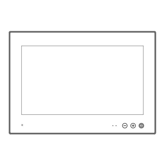
User Controls USER CONTROLS OVERVIEW The units are designed using Glass Display Control™ (GDC) touch technology to allow interactivity adjusting brilliance (brightness) and control power on / off. All symbols are silkprinted in white on the front glass, and are backlight illuminated when suitable power is connected.There are no physical moving knobs, potmeters, wheels or push buttons available as everything is touch surface controlled by Projected Capacitive technology, that allows a human finger (including several types of gloves) to control the unit. - Page 39 User Controls Power ON/OFF (UserKey3): Touching this symbol will either turn on or off the unit. When the power cable is connected to the unit the symbol will not be illuminated until the unit has been turned on once. Symbols will Illuminate in white. When no power cable is connected, the symbols will not be illuminated.
- Page 40 This page left intentionally blank...
-
Page 41: Specifications
Specifications... -
Page 42: Specifications - Hd 08T30 Mmc-2Xx-Xxxxax
Specifications - HD 08T30 MMC-2xx-xxxxAx SPECIFICATIONS Note: All specifi cations are subject to change without prior notice! Please visit www.hattelandtechnology.com for the latest electronic version. All specifications are subject to change without prior notice! TFT Technology: Physical Dimensions: • 8.0 inch TFT Liquid Crystal Display module, IPS (in-plane-switching) •... -
Page 43: Specifications - Hd 08T30 Mmc-2Xx-Xxxxax (Hw00)
Specifications - HD 08T30 MMC-2xx-xxxxAx (HW00) SPECIFICATIONS Note: All specifi cations are subject to change without prior notice! Please visit www.hattelandtechnology.com for the latest electronic version. All specifications are subject to change without prior notice! TFT Technology: Physical Dimensions: • 8.0 inch TFT Liquid Crystal Display module, TN (Twisted Nematic) •... -
Page 44: Specifications - Hd 08T30 Mmc-2Xx-Xxxxhx
Specifications - HD 08T30 MMC-2xx-xxxxHx SPECIFICATIONS Note: All specifi cations are subject to change without prior notice! Please visit www.hattelandtechnology.com for the latest electronic version. All specifications are subject to change without prior notice! Physical Dimensions: TFT Technology: • W:228.00 [9.01''] x H:156.60 [6.17''] x D:75.10 [2.96''] mm [inch] •... -
Page 45: Specifications - Hd 08T30 Mmc-2Xx-Xxxxhx (Hw00)
Specifications - HD 08T30 MMC-2xx-xxxxHx (HW00) SPECIFICATIONS Note: All specifi cations are subject to change without prior notice! Please visit www.hattelandtechnology.com for the latest electronic version. All specifications are subject to change without prior notice! Physical Dimensions: TFT Technology: • W:228.00 [9.01''] x H:156.60 [6.17''] x D:75.10 [2.96''] mm [inch] •... -
Page 46: Specifications - Hd 08T30 Mmc-2Xx-Xxxeax
Specifications - HD 08T30 MMC-2xx-xxxEAx SPECIFICATIONS Note: All specifi cations are subject to change without prior notice! Please visit www.hattelandtechnology.com for the latest electronic version. All specifications are subject to change without prior notice! Physical Dimensions: TFT Technology: • W:236.00 [9.29''] x H:166.00 [6.54''] x D:62.70 [2.47''] mm [inch] •... -
Page 47: Specifications - Hd 08T30 Mmc-2Xx-Xxxeax (Hw00)
Specifications - HD 08T30 MMC-2xx-xxxEAx (HW00) SPECIFICATIONS Note: All specifi cations are subject to change without prior notice! Please visit www.hattelandtechnology.com for the latest electronic version. All specifications are subject to change without prior notice! Physical Dimensions: TFT Technology: • W:236.00 [9.29''] x H:166.00 [6.54''] x D:62.70 [2.47''] mm [inch] •... -
Page 48: Specifications - Hd 08T30 Mmc-2Xx-Xxxehx
Specifications - HD 08T30 MMC-2xx-xxxEHx SPECIFICATIONS Note: All specifi cations are subject to change without prior notice! Please visit www.hattelandtechnology.com for the latest electronic version. All specifications are subject to change without prior notice! Physical Dimensions: TFT Technology: • W:236.00 [9.29''] x H:166.00 [6.54''] x D:75.10 [2.96''] mm [inch] •... -
Page 49: Specifications - Hd 08T30 Mmc-2Xx-Xxxehx (Hw00)
Specifications - HD 08T30 MMC-2xx-xxxEHx (HW00) SPECIFICATIONS Note: All specifi cations are subject to change without prior notice! Please visit www.hattelandtechnology.com for the latest electronic version. All specifications are subject to change without prior notice! Physical Dimensions: TFT Technology: • W:236.00 [9.29''] x H:166.00 [6.54''] x D:75.10 [2.96''] mm [inch] •... -
Page 50: Specifications - Hd 13T30 Mmc-2Xx-Xxxxax
Specifications - HD 13T30 MMC-2xx-xxxxAx SPECIFICATIONS Note: All specifi cations are subject to change without prior notice! Please visit www.hattelandtechnology.com for the latest electronic version. All specifications are subject to change without prior notice! TFT Technology: Physical Dimensions: • 13.3 inch TFT Liquid Crystal Display module, TN (Twisted Nematic) •... -
Page 51: Specifications - Hd 13T30 Mmc-2Xx-Xxxxhx
Specifications - HD 13T30 MMC-2xx-xxxxHx SPECIFICATIONS Note: All specifi cations are subject to change without prior notice! Please visit www.hattelandtechnology.com for the latest electronic version. All specifications are subject to change without prior notice! TFT Technology: Physical Dimensions: • 13.3 inch TFT Liquid Crystal Display module, TN (Twisted Nematic) •... - Page 52 This page left intentionally blank...
-
Page 53: Specifications Accessories
Specifications Accessories... -
Page 54: Specifications - Jh C01Mf A-A
Specifications - JH C01MF A-A This information may not, in whole or in part, be copied, photocopied, DATASHEET reproduced, translated or reduced to any electronic medium or machine- readable form without the prior written consent of Hatteland Technology AS. The products may not be copied or duplicated in any way. Hatteland Technology AS Manufacturer: ACCESSORY... -
Page 55: Specifications - External Modules (Usb)
Specifications - External Modules (USB) Specifications - External Modules (USB) All specifications are subject to change without prior notice! This information may not, in whole or in part, be copied, photocopied, DATASHEET reproduced, translated or reduced to any electronic medium or machine- readable form without the prior written consent of Hatteland Technology AS. - Page 56 Specifications - External Modules (USB) All specifications are subject to change without prior notice! SPECIFICATIONS Note: All specifi cations are subject to change without prior notice! Please visit www.hattelandtechnology.com for the latest electronic version. Ordering Details: TypeNumber Description Internal Specifications (link to separate datasheets) HT 00262 OPT-A1 NMEA COM (Based on PCA200828-1) 4 x NMEA RS-422/RS-485 isolated...
-
Page 57: Technical Drawings
Technical Drawings... -
Page 58: Technical Drawings - Hd 08T30 Mmc-2Xx-Xxxxax
Technical Drawings - HD 08T30 MMC-2xx-xxxxAx Standard Model IND100132-403... -
Page 59: Standard Model - Hw00
Technical Drawings - HD 08T30 MMC-2xx-xxxxAx Standard Model - HW00 IND100132-403... -
Page 60: Technical Drawings - Hd 08T30 Mmc-2Xx-Xxxxhx
Technical Drawings - HD 08T30 MMC-2xx-xxxxHx With HD IO-Board IND100132-405... -
Page 61: With Hd Io-Board - Hw00 Model
Technical Drawings - HD 08T30 MMC-2xx-xxxxHx With HD IO-Board - HW00 Model IND100132-405... -
Page 62: Technical Drawings - Hd 08T30 Mmc-2Xx-Xxxxax
Technical Drawings - HD 08T30 MMC-2xx-xxxxAx RetroFit HD 08T21 IND100132-412... -
Page 63: Retrofit Hd 08T21 - Hw00 Model
Technical Drawings - HD 08T30 MMC-2xx-xxxxAx RetroFit HD 08T21 - HW00 Model IND100132-412... -
Page 64: Technical Drawings - Hd 08T30 Mmc-2Xx-Xxxxhx
Technical Drawings - HD 08T30 MMC-2xx-xxxxHx RetroFit HD 08T21 w/ HD IO-Board IND100132-411... -
Page 65: Retrofit Hd 08T21 W/ Hd Io-Board - Hw00 Model
Technical Drawings - HD 08T30 MMC-2xx-xxxxHx RetroFit HD 08T21 w/ HD IO-Board - HW00 Model IND100132-411... -
Page 66: Technical Drawings - Hd 08T30 Mmc-2Xx-Xxxxxx
Technical Drawings - HD 08T30 MMC-2xx-xxxxxx Console Mounting IND100132-407... -
Page 67: Technical Drawings - Hd 08T30 Mmc-2Xx-Xxxxxx
Technical Drawings - HD 08T30 MMC-2xx-xxxxxx External Fan Accessory IND100132-408... -
Page 68: External Fan Accessory - Hw00 Model
Technical Drawings - HD 08T30 MMC-2xx-xxxxxx External Fan Accessory - HW00 Model IND100132-408... -
Page 69: Technical Drawings - Hd 13T30 Mmc-2Xx-Xxxxax
Technical Drawings - HD 13T30 MMC-2xx-xxxxAx Standard Model IND100132-404... -
Page 70: Standard Model - Hw00 Model
Technical Drawings - HD 13T30 MMC-2xx-xxxxAx Standard Model - HW00 Model IND100132-404... -
Page 71: Technical Drawings - Hd 13T30 Mmc-2Xx-Xxxxhx
Technical Drawings - HD 13T30 MMC-2xx-xxxxHx With HD IO-Board IND100132-406... -
Page 72: With Hd Io-Board - Hw00 Model
Technical Drawings - HD 13T30 MMC-2xx-xxxxHx With HD IO-Board - HW00 Model IND100132-406... -
Page 73: Technical Drawings - Hd 13T30 Mmc-2Xx-Xxxxxx
Technical Drawings - HD 13T30 MMC-2xx-xxxxxx Console Mounting IND100132-409... -
Page 74: Technical Drawings - Hd 13T30 Mmc-2Xx-Xxxxxx
Technical Drawings - HD 13T30 MMC-2xx-xxxxxx External Fan Accessory IND100132-410... -
Page 75: External Fan Accessory - Hw00 Model
Technical Drawings - HD 13T30 MMC-2xx-xxxxxx External Fan Accessory - HW00 Model IND100132-410... -
Page 76: Technical Drawings - Hd 13T30 Mmc-2Xx-Xxxxxx
Technical Drawings - HD 13T30 MMC-2xx-xxxxxx With Desktop/Table Mounting Bracket IND100132-426... -
Page 77: Technical Drawings - Accessories
Technical Drawings - Accessories... -
Page 78: Technical Drawings - Hd Cmb Sx2-B1
Technical Drawings - HD CMB SX2-B1 Console Mount Kit 7 inch/8 inch IND100132-400... -
Page 79: Technical Drawings - Hd Cmb Sx2-C1
Technical Drawings - HD CMB SX2-C1 Console Mount Kit 13 inch IND100132-399... -
Page 80: Technical Drawings - Hd Fan Sx2-A1
Technical Drawings - HD FAN SX2-A1 External Fan Kit 8/13 inch IND100132-413... -
Page 81: Technical Drawings - P015955 - Usb Support Bracket
Technical Drawings - P015955 - USB Support Bracket Part of HD KIT USB-A1 IND100132-414... -
Page 82: Technical Drawings - Usbc-24
Technical Drawings - USBC-24 Dust Cover for USB IND100132-416... -
Page 83: Technical Drawings - Pjc-45
Technical Drawings - PJC-45 Dust Cover for LAN IND100132-417... -
Page 84: Technical Drawings - Hd Tmb Sx2-A4
Technical Drawings - HD TMB SX2-A4 Desktop/Table Mounting Bracket 8 inch IND100132-455... - Page 85 Technical Drawings - HD TMB SX2-A4 Desktop/Table Mounting Bracket 8 inch IND100132-455...
-
Page 86: Technical Drawings - Hd Tmb Sx2-A3
Technical Drawings - HD TMB SX2-A3 Desktop/Table Mounting Bracket 13 inch IND100132-415... -
Page 87: Technical Drawings - Hd Ved Sx2-L1
Technical Drawings - HD VED SX2-L1 VESA Adapter Kit 8/13 inch IND100132-456... - Page 88 Technical Drawings - HD VED SX2-L1 VESA Adapter Kit 8/13 inch IND100132-456...
- Page 89 Technical Drawings - HD VED SX2-L1 VESA Adapter Kit 8/13 inch IND100132-456...
-
Page 90: Technical Drawings - Hd Ved Sx2-L2
Technical Drawings - HD VED SX2-L2 VESA Adapter Kit 8/13 inch IND100132-457... - Page 91 Technical Drawings - HD VED SX2-L2 VESA Adapter Kit 8/13 inch IND100132-457...
-
Page 92: Technical Drawings - Hd 08Cov Std-A1
Technical Drawings - HD 08COV STD-A1 UV Sun Cover (8 inch) IND100132-418... -
Page 93: Technical Drawings - Hd 13Cov Std-A1
Technical Drawings - HD 13COV STD-A1 UV Sun Cover (13 inch) IND100132-419... -
Page 94: Frame Adapter (For Hd 08T21 Cutout Retrofit)
Technical Drawings - HD 08TAP SX1-A1 Frame Adapter (for HD 08T21 Cutout RetroFit) IND100132-450... -
Page 95: Technical Drawings - P023456
Technical Drawings - P023456 IP66 Panel Gasket (8” RetroFit HD 07T22) IND100132-444... -
Page 96: Technical Drawings - P014338
Technical Drawings - P014338 IP66 Panel Gasket (8” RetroFit HD 08T21) IND100132-443... -
Page 97: Technical Drawings - P014441
Technical Drawings - P014441 IP66 Panel Gasket (13” RetroFit HD 13T21/T22) IND100132-445... -
Page 98: Technical Drawings - Hd Wbk Sx1-A3
Technical Drawings - HD WBK SX1-A3 Wall Mount Box Kit for 8 inch models IND100132-518... -
Page 99: Technical Drawings - External Modules (Usb)
Technical Drawings - External Modules (USB) IND100132-245... - Page 100 This page left intentionally blank...
-
Page 101: Appendixes
Appendixes... -
Page 102: Additional Features Overview/Details
Additional features overview/details Trusted Platform Module (TPM) TPM 2.0 module with support for TPM 1.2 is included. This is a security device designed to secure the system using integrated cryptographic keys. Support and requirements: - Only supported for OS installed as UEFI boot. Legacy boot is not supported. - Secure Boot must be configured and enabled for full TPM functionality to be available. -
Page 103: Secure Boot
Additional features overview/details Secure Boot Secure Boot is a security feature that can protect the system from running unauthorized boot loaders and avoid loading non-signed drivers during boot process. The feature is only supported for boot devices in UEFI mode. CSM Support (BIOS Legacy boot and Option ROM support) is not compatible with this security feature and must be disabled in BIOS before enabling Secure Boot. -
Page 104: Battery Status And Alarm
Additional features overview/details Battery Status and Alarm CMOS battery voltage is monitored during each boot and the following warning will show if it’s below set low limit: WARNING!!! The CMOS battery capacity too low. If this error is displayed, it is recommended to schedule service of the unit for replacement of CMOS battery. When the CMOS battery is dead, or voltage is too low, it will not keep track of time/date when power is disconnected. -
Page 105: Lan Teaming
Additional features overview/details LAN Teaming The network ports support VLAN and Teaming functionality. For Windows 10, Intel Network Connections version 23.2.x or newer is required. For Linux OS, adapter teaming is implemented using the native Linux Channel bonding module. Latest Intel network driver/software is available at: https://downloadcenter.intel.com/product/64402/Intel-Ethernet-Controller-I210-IT Procedure to set up teaming in Windows 10: - Open Device Manager and expand Network adapters... - Page 106 Additional features overview/details - Select team type from list, then press Next. - Select Next/Finish to confirm and create team. - If notification about jumbo packet limitation is shown, press OK. Appendix IND100077-197...
-
Page 107: Reading Internal Temperature
Additional features overview/details Reading internal temperature SCOM* command “TMP” can be used to read out internal temperature sensor value. *If you are not familiar with the SCOM protocol, please review the Hatteland Technology’s Serial Remote Control Interface (SCOM) protocol document can be downloaded from: https://www.hattelandtechnology.com/hubfs/pdfget/inb100018-7.htm COM Ports Numbering Default numbering on a factory standard model (example: Microsoft®... -
Page 108: Install Microsoft® Windows® 10 With Recovery Option
Additional features overview/details Install Microsoft® Windows® 10 with recovery option 1: Boot to Windows 10 installer 2: Select language settings 3: Click “Repair your computer” 4: Click “Troubleshoot” 5: Click “Command Line” and type the following indicated in a black box below. - Page 109 Additional features overview/details Step 6 - Finalize installation ======================= Reboot the computer and complete normal Windows setup Activate Windows Update Windows and install missing drivers Set up Windows and software to default state Step 7 - Set up backup ======================= Aquire Wimlib binaries from https://wimlib.net Windows 64bit:...
- Page 110 Additional features overview/details "DiskPart_Pre-install.txt" script contents REM ====================================================== REM ===== DiskPart_Pre-install.txt ===== REM ===== ===== REM ===== These commands are used with DiskPart ===== REM ===== to create four partitions for a ===== REM ===== UEFI/GPT-based PC. ===== REM ===== ===== REM ===== Adjust the partition sizes to fill =====...
- Page 111 Additional features overview/details "DiskPart_Post-install.txt" script contents REM ================================================ REM ===== DiskPart_Post-install.txt ===== REM ===== Post install script ===== REM ===== ===== REM ===== This should be run after copying ===== REM ===== WinRE to recovery partition ===== REM ================================================ REM ================================================ REM ===== 1 Setting hidden flag for ===== REM ===== Recovery partition...
-
Page 112: Rtc Timer (Apollolake) - User Guide
RTC Timer (Apollolake) - User Guide User Guide RTC Timer - ApolloLake All intellectual properties belongs to Hatteland Display AS DOC207017- rev 01 – 2018-09-24 - Created by: 6644 User Guide RTC Timer (ApolloLake) Appendix IND100077-195... - Page 113 User Guide RTC Timer - ApolloLake RTC Timer (Apollolake) - User Guide User Guide RTC Timer - ApolloLake All intellectual properties belongs to Hatteland Display AS DOC207017- rev 01 – 2018-09-24 - Created by: 6644 All intellectual properties belongs to Hatteland Display AS DOC207017- rev 01 –...
- Page 114 RTC Timer (Apollolake) - User Guide User Guide RTC Timer - ApolloLake All intellectual properties belongs to Hatteland Display AS DOC207017- rev 01 – 2018-09-24 - Created by: 6644 1 Description APOLLOLAKE S/L motherboard is equipped with accurate external RTC chip. It can hold the time accurately under absence of NTP time server.
- Page 115 User Guide RTC Timer - ApolloLake RTC Timer (Apollolake) - User Guide All intellectual properties belongs to Hatteland Display AS DOC207017- rev 01 – 2018-09-24 - Created by: 6644 However, when the system is shutdown or restart, the BIOS firmware has no chance to do the time copy, then the time of external RTC timer is not up-to-date.
- Page 116 RTC Timer (Apollolake) - User Guide User Guide RTC Timer - ApolloLake All intellectual properties belongs to Hatteland Display AS DOC207017- rev 01 – 2018-09-24 - Created by: 6644 Wait 1 sec Read Execute Bit Base Address + (Expected 0x08) 0x02 Read Returned Base Address +...
- Page 117 0x02 Wait 1 sec Read Execute Bit Base Address + (Expected 0x08) 0x02 User Guide RTC Timer - ApolloLake RTC Timer (Apollolake) - User Guide All intellectual properties belongs to Hatteland Display AS DOC207017- rev 01 – 2018-09-24 - Created by: 6644 Note: 1.
- Page 118 User Guide RTC Timer - ApolloLake RTC Timer (Apollolake) - User Guide All intellectual properties belongs to Hatteland Display AS DOC207017- rev 01 – 2018-09-24 - Created by: 6644 typedef short (__stdcall *lpInp32)(short); lpOut32 gfpOut32; lpInp32 gfpInp32; //Base Address Read unsigned char SlaveDeviceReadByte(unsigned char bSlaveDeviceAddr, unsigned char...
- Page 119 User Guide RTC Timer - ApolloLake RTC Timer (Apollolake) - User Guide All intellectual properties belongs to Hatteland Display AS DOC207017- rev 01 – 2018-09-24 - Created by: 6644 unsigned char bValue = 0; //1. Clear host status gfpOut32(iBaseAddrSMBUS + bOffsetHostStatus, 0xFE); //2.
- Page 120 User Guide RTC Timer - ApolloLake RTC Timer (Apollolake) - User Guide All intellectual properties belongs to Hatteland Display AS DOC207017- rev 01 – 2018-09-24 - Created by: 6644 bRTCFormatValue = 1 << bTimeValue; return bRTCFormatValue; void Main(void) … //Write to RTC timer cout <<...
- Page 121 User Guide RTC Timer - ApolloLake RTC Timer (Apollolake) - User Guide All intellectual properties belongs to Hatteland Display AS DOC207017- rev 01 – 2018-09-24 - Created by: 6644 ioperm() sets the port access permission bits for the calling thread for num bits starting from port addressfrom.
-
Page 122: Bios Default Settings Overview
BIOS Default Settings Overview BIOS Setup Values Doc No. Board: APOLLOS BIOS: APOLLOS-X2I-190115 1. Setup pages and values APOLLOSX2IA - 8 inch APOLLOSX2IB - 13 inch Items Standard BIOS default setting comment Main> BIOS Information BIOS Version APOLLOS-X2I-190115 Memory Information Total Memory xxxx BM xxxx MHz... - Page 123 BIOS Setup Values BIOS Default Settings Overview Doc No. Board: APOLLOS BIOS: APOLLOS-X2I-190115 1. Setup pages and values APOLLOSX2IA - 8 inch APOLLOSX2IB - 13 inch Items Standard BIOS default setting comment Main> LVDS (eDP/DP) Configuration BIOS Information [Disabled] [18bit, Single Channel] [18bit, Single Channel] LVDS (eDP/DP) Controller [Enabled]*...
- Page 124 BIOS Default Settings Overview [Always On] * Power Mode [Power Button Only] [Previous State] [Disabled] GPO Reset [Enabled] * RS232 Mode* RS232 Mode, without termination RS422/485 Full Duplex, o/ termination RS422/485 Full Duplex Mode, without receiver termination COM2 (IOH) RS422/485 Full Duplex, w/ termination RS422/485 Full Duplex Mode, with receiver termination RS485 Half Duplex o/ termination RS485 Half Duplex Mode, without receiver termination...
- Page 125 BIOS Default Settings Overview H/W Monitor PC Health Status [Disabled] * 50 C 60 C Smart Fan 1 Function 70 C 80 C 90 C [CPU Temperature] * Temperature Source SYS Temperature [Disabled] * [70 C/158 F] [75 C/167 F] ACPI Shutdown Temperature [80 C/176 F] [85 C/185 F]...
- Page 126 BIOS Default Settings Overview CSM Configuration Compability Support Module Configuration [Disabled] CSM Support [Enabled]* Sub menu is visible only when this item is Enabled 7.79 CSM10 Module Version [Upon Request] * GateA20 Active [Always] [Immediate] * INT19 Trap Response [Postponed] [UEFI and Lagacy] * Boot option filter [Lagacy only]...
- Page 127 BIOS Default Settings Overview Chipset> South Cluster Configuration HD-Audio Configuration [Enabled] * HD-Audio Support Disabled SATA Device Chipset-SATA Controller Configuration [Enabled] * Chipset SATA Disabled [AHCI] * SATA Mode Selection SATA Port 0 SATA Port 1 USB Configuration [Enable] XHCI Pre-Boot Driver [Disable] * [Enable] * XHCI Mode...
- Page 128 BIOS Default Settings Overview Security> Password Description Setup Administrator Password User Password Boot> Boot Configuration [1]* Setup Prompt Timeout 1 .. 65535 [On]* Bootup NumLock State [Off] [Disabled] * Quiet Boot [Enabled] * [Disabled] * Fast Boot [Enabled] [LAGACY] Boot mode selection [UEFI] * [DUAL] FIXED BOOT ORDER Priorities...
-
Page 129: Watchdog Timer Function
WatchDog Timer function WatchDog functions provided by Hatteland Technology: If you are not familiar with the SCOM protocol, please review the Hatteland Technology's Serial Remote Control Interface (SCOM) protocol document can be downloaded from: https://www.hattelandtechnology.com/hubfs/pdfget/inb100018-7.htm Suitable commands: "WDF" - Software Watchdog Feed "WDC"... -
Page 130: Basic Trouble-Shooting
Basic Trouble-shooting GENERAL ISSUES FOR TFT PANEL BASED PRODUCTS Note: Applies for a range of various products. This is only meant as a general guide. O PICTURE / LED BEHAVIOUR: If there is no light at all in the LED at the FRONT, check power cables. If the LED in front is green, then check if the brightness is set/adjusted to max brightness. -
Page 131: Trouble-Shooting
Trouble-shooting Operating System Recovery (tool) Reference: DOC207939-1 The tool described in this chapter is available directly from Support at Hatteland Technology. In order to receive a copy of the software (Windows 10 only) and the appropriate matching OS image to your exact product model, please have a complete unit’s Type number and Serial number ready prior to contacting Support at Hatteland Technology (or https://www.hattelandtechnology.com/support/contact through dedicated Service Partner channels) via:... - Page 132 Trouble-shooting DOC207939-1 - Revision 03 You will be prompted to confirm that the selected USB will be completely wiped of all data. The USB-stick chosen will have all its data deleted. 4. The program will run for a couple of minutes, the speed of the creator depends on the speed of the operating system and the USB-stick.
- Page 133 Trouble-shooting DOC207939-1 - Revision 03 1.3 Using the USB Recovery Solution 1.3.1 Prerequisites This solution only works on Hatteland Technology Panel Computers and Hatteland Technology Computers. This solution does not support “Legacy” BIOS, only UEFI is supported. 1.3.2 How-to-use Boot into your USB-stick, by pressing “F7”-key during start-up of your Hatteland Technology Panel Computer.
- Page 134 Trouble-shooting DOC207939-1 - Revision 03 1.3.2.2 Recovery The Recovery buttons opens the recovery function. You select the target drive you wish to recover. The description in the large box is the description of the image. When you press “ok”, you will get a final warning that the target drive will be wiped and all data on the drive will be lost.
-
Page 135: How To Activate Windows Recovery Environment On Os Drive
Trouble-shooting How to activate Windows Recovery Environment on OS Drive Reference: DOC208258-1 Products delivered before Q1-2021 from Hatteland Technology may not have Windows Recovery Environment present. DOC208258-1 - Revision 01 The Windows Recovery Environment must be manually activated before it can be used. Please follow the steps below. How to activate WinRE 1. -
Page 136: Pinout Assignments
Pinout Assignments Connectors illustrated here are either standard by factory default or may be available (through factory customization). Note that some combinations may not be possible due to space restrictions. List also valid for customized models. All pin out assignments are seen from users Point of View (POV) while looking straight at the connector. Please review the dedicated datasheet or technical drawings for your actual unit to identify and determine the presence of desired connector. - Page 137 Pinout Assignments Additional HD IO-Board Connectors: 5-pin Isolated NMEA COM COM Ports are identifed in the Operating System “RS-422/RS-485” (example Microsoft® Windows® 10) as: COMx (A), COMx (B), COMx (C), COMx (D)* *COM ports are not reserved nor locked by BIOS. x indicate a numeric number from 1-99.
- Page 138 4 channel RS-422 / RS-485, NMEA / IEC COM Module Description: The Hatteland Technology COM modules provide the system with quad independent COM channels. The module is attached to the Pinout Assignments motherboard via standard USB interface. Application software access the COM channels as standard COM devices, i.e. in the normal case is there no requirements for additional software development.
- Page 139 Pinout Assignments NMEA Standards: IEC61162-1 chapter 3.5.5 state that the input shall withstand 15V between ground and input. The reference speed specified is set at 4800 bit/s. IEC61162-2 chapter 3.1 state that there are 3 wires to be used. (A, B and C). The reference speed for this interface is set as 38400 bit/s.
- Page 140 Pinout Assignments Additional HD IO-Board Connectors: 5-pin Isolated CAN I/O, 2 channels CAN H M12, NMEA2000 Connector 120Ω 120Ω CAN L CAN Node CAN Node CAN Node Cable Stub Length CAN H CAN H CAN H Notch CAN L CAN L CAN L Note: 110/120Ω...
- Page 141 Pinout Assignments Additional HD IO-Board Connectors: Serial Communication settings configured in BIOS: “Advanced/F81964 Super IO Configuration/SuperIO Chip/ COM Port is identified in (Windows) Operating System as “COM2:” 9-pin non-isolated Serial COM DSUB Male 9-pin non-isolated Serial COM DSUB MALE 9-pin non-isolated Serial COM DSUB MALE RS-232 RS-422 / RS-485 FULL DUPLEX RS-485 HALF DUPLEX...
- Page 142 Pinout Assignments Additional HD IO-Board Connectors: 5-pin Isolated Digital Input / Output “2 x IN + 2 x OUT Digital” PIN 01 IN+[0] PIN 02 IN+[1] PIN 03 Common (Signal Ground) PIN 04 OUT+[0] PIN 05 OUT+[1] SPECIFICATIONS Note: All specifi cations are subject to change without prior notice! IO controlled through the Serial SPECIFICATIONS Please visit www.hattelandtechnology.com for the latest electronic version.
-
Page 143: Iec62368 Policy For Hatteland Technology Products
IEC62368 policy for Hatteland Technology products Introduction According to the requirements of EN 62368-1:2014. The tables below refers to the policies for opening, servicing and installation of the unit(s) referred to in this manual. This equipment is designed to be used as a fixed installation and to be sold through special sales channels for professional use. - Page 144 IEC62368 policy for Hatteland Technology products Authority Description Children This equipment is not suitable for use in locations where children are likely to be present. Ordinary person/ Not allowed to open unit. Sailor/End-User Not allowed to install the unit. Not allowed to terminate/connect cables to the unit. Instructed person Allowed to open hatches/latches which does not require tools, such as Disktrays.
-
Page 145: Declaration Of Conformity
Declaration of Conformity We, manufacturer, Hatteland Technology AS, Eikeskogvegen 52, N-5570 Aksdal, Norway declare under our sole responsibility that the JH MMD, JH MMC, JH STD, JH MIL, HM NMD, HM MIL, HM CMD, HT STD, HD MMD, HD MVD, HM MMD, HM XRD, HM RMD, HT MMC, HD MMC, HT/HM (computers) and HN G (Network Switches) product ranges is in conformity with the following standards in accordance with the EMC Directive. -
Page 146: Return Of Goods Information
Return Of Goods Information Return of goods: (Applies not to warranty/normal service/repair of products) Hatteland Technology referenced as “manufacturer” in this document. Before returning goods, please contact your system supplier before sending anything directly to manufacturer. When you return products after loan, test, evaluation or products subject for credit, you must ensure that all accessories received from our warehouse are returned. -
Page 147: General Terms And Conditions
General Terms and Conditions As of January 2015, Hatteland Technology AS’ “Terms of Sales and Delivery” and “Warranty Terms” have been substituted by the updated ”General terms and conditions for sale of goods and performance of additional services” (the “General Terms and Conditions”). Further, from January 2015 onward, the previous “Terms of Sales and Delivery”... -
Page 148: Pixel Defect Policy
Pixel Defect Policy PIXEL DEFECT POLICY Dot-defects (Bright or dark spots on the panel) Due to the effect that dot failures are part of the TFT technology such failure occurrence cannot be prevented basically. Even though dot defects usually occur during production process, new defects can appear within the lifespan of a TFT display. Neither the production at LCD-supplier nor the use of an LCD-Monitor after shipment can be influenced by Hatteland Technology. -
Page 149: Parts And Recycling
Parts and Recycling Rev 02 - 20 May 2021 Parts in Displays and Panel Computers, and how to recycle Part Where to dispose of parts TFT Panel Electrical waste Optically bonded units: the TFT Panel, Glass Metal waste Glass and frame is to be disposed of as Electrical waste. -
Page 150: Notes
Notes General Notes: - The unit is tested according to IEC 60945 4th (EN 60945:2002), 4.4, equipment category b) “protected from the weather (formerly class B)”. - Other type approvals applies for the different products. Please see the appropriate “Specifications” page in this manual for more information. - Use of brillance and Glass Display Control™... - Page 151 User Notes Appendix IND100077-24...
-
Page 152: Revision History
Revision History Rev. Date Notes 00_01 05 Dec 2018 Release for internal review. 00_02 21 Dec 2018 Revised after internal reviews. 00_03 12 Feb 2019 Revised after internal reviews. 00_04 01 Mar 2019 Revised after internal reviews 00_05 19 Mar 2019 Revised after internal reviews 05 Apr 2019 Final release for internet... - Page 153 Revision History Appendix IND100077-194...
- Page 154 Hatteland Technology AS | www.hattelandtechnology.com | Enterprise no: NO974533146...
Need help?
Do you have a question about the HATTELAND HD 08T30 Series and is the answer not in the manual?
Questions and answers