Table of Contents
Advertisement
Quick Links
USER MANUAL
Series X G2 - Maritime Multi Display (MMD) Models
HD 15T22 MMD-xxx-Fxxx - 15.0 inch Maritime Multi Display
HD 17T22 MMD-xxx-Fxxx - 17.0 inch Maritime Multi Display
HD 19T22 MMD-xxx-Fxxx - 19.0 inch Maritime Multi Display
HD 24T22 MMD-xxx-Fxxx - 24.0 inch Maritime Multi Display
HD 24T23 MMD-xxx-Fxxx - 24.0 inch Maritime Multi Display
HD 26T22 MMD-xxx-Fxxx - 25.54 inch Maritime Multi Display
HD 27T22 MMD-xxx-Fxxx - 27.0 inch Maritime Multi Display
Updated: 01 Dec 2021
Created: 363
Please visit www.hattelandtechnology.com for the latest electronic version of this manual.
User Manual MMD Series X G2
03 Oct 2022
Doc Id: INB101192-1 (Rev 23)
Approved: 362
(Rev 26)
Advertisement
Table of Contents

Related Manuals for EMBRON Hatteland Technology HD 15T22 MMD F Series


Summary of Contents for EMBRON Hatteland Technology HD 15T22 MMD F Series
- Page 1 USER MANUAL Series X G2 - Maritime Multi Display (MMD) Models HD 15T22 MMD-xxx-Fxxx - 15.0 inch Maritime Multi Display HD 17T22 MMD-xxx-Fxxx - 17.0 inch Maritime Multi Display HD 19T22 MMD-xxx-Fxxx - 19.0 inch Maritime Multi Display HD 24T22 MMD-xxx-Fxxx - 24.0 inch Maritime Multi Display HD 24T23 MMD-xxx-Fxxx - 24.0 inch Maritime Multi Display HD 26T22 MMD-xxx-Fxxx - 25.54 inch Maritime Multi Display HD 27T22 MMD-xxx-Fxxx - 27.0 inch Maritime Multi Display...
- Page 2 Copyright © 2022 Hatteland Technology AS Eikeskogvegen 52, N-5570 Aksdal, Norway. All rights are reserved by Hatteland Technology AS. This information may not, in whole or in part, be copied, photocopied, reproduced, translated or reduced to any electronic medium or machine- readable form without the prior written consent of Hatteland Technology AS.
-
Page 3: Table Of Contents
Contents Contents ..................3 Contents of package ....................9 General ..................11 IEC62368 policy - Introduction ...................12 About this manual ......................13 About Hatteland Technology ..................13 www.hattelandtechnology.com ...................13 Contact Information ....................13 Maritime Multi Display (MMD) Generation 2 (G2) - Introduction ........14 Touch screen products ....................15 Product Labeling ......................18 Installation .................. -
Page 4: Contents
Contents Operation ..................43 User Controls ......................44 On Screen Display (OSD) Menu Introduction ............46 OSD Key Code (password) overview .................46 OSD Keycode / OSD Lock Mode ................47 OSD “Basic”, “Advanced” & “Service” Menu modes ..........48 OSD Visual Feedback (examples) ................48 OSD Menu Structure ....................49 Input Source Settings ..................... - Page 5 Contents Technical Drawings ..............97 Technical Drawings - HD 15T22 MMD-xxx-Fxxx ............98 Technical Drawings - HD 15T22 MMD-xxx-FHxx ............99 High Bright model....................99 Technical Drawings - HD 17T22 MMD-xxx-Fxxx ............100 Technical Drawings - HD 17T22 MMD-xxx-FHxx .............101 High Bright model....................101 Technical Drawings - HD 19T22 MMD-xxx-Fxxx ............102 HW00 Model ......................
- Page 6 Contents Technical Drawings - HD CMB SX2-A1 ..............127 Console Mount Kit 19 inch ................... 127 Technical Drawings - HD CMB SX2-E1 ..............128 Console Mount Kit 24 inch ................... 128 Console Mounting 24 inch ................... 129 P006801-1 Flush Mounting 24 inch ..............130 Technical Drawings - HD CMB SX2-F1 ..............131 Console Mount Kit 26 inch ...................
- Page 7 Contents Technical Drawings - HD 24COV SX1-A1 ..............152 UV Sun Cover (24 inch) ..................152 Technical Drawings - HD 26COV SX1-A1 ..............153 UV Sun Cover (26 inch) ..................153 Technical Drawings - HD 27COV SX1-A1 ..............154 UV Sun Cover (27 inch) ..................154 Technical Drawings - HD CAK SX2-A1 ..............155 Front Console Mounting/Adapter Kit (24 inch) .............
- Page 8 This page left intentionally blank IND100130-2...
-
Page 9: Contents Of Package
Contents of package Note: Entries listed below are for Standard factory shipments. Customized factory shipments may deviate from this list. Item Description Illustration 1 x Standard DVI Signal Cable. DVI-D 18+1P Male to DVI-D 18+1P Male Single Link - Length 2.0m HA-SDM-2M 1 x Standard VGA Signal Cable. - Page 10 Contents of package Package may also include: Item Description Illustration 1 x Touch Screen Cable (Black) USB Type A to Type A. Length Approx 2m. Only included in package if model is equipped with factory mounted Touch Screen VSD100913-1 For models (15-27 inch) an EPDM sealing gasket for IP66 console mount may be factory pre-mounted / included with delivery if ordered.
-
Page 11: General
General IND100130-2... -
Page 12: Iec62368 Policy - Introduction
IEC62368 policy - Introduction Safety Instructions Please read and understand the material in this manual in its entirety before doing any installation/servicing/upgrades. Personnel who are allowed to do work on the unit is detailed in the “IEC62368 policy for Hatteland Technology product”... -
Page 13: About This Manual
Hatteland Technology AS About this manual The manual contains electrical, mechanical and input/output signal specifications. All specifications in this manual, due to manufacturing, new revisions and approvals, are subject to change without notice. However, the last updated and revision date of this manual are shown both on the frontpage and also in the “Revision History” chapter. This user manual is a standard/general manual that applies to all variations of its product family, i.e. -
Page 14: Maritime Multi Display (Mmd) Generation 2 (G2) - Introduction
Displays Series X Generation 2 (G2) Maritime Multi Display (MMD) Generation 2 (G2) - Introduction As a leading manufacturer of display and computer hardware for the maritime segment, Hatteland Technology continuously gauges and responds to market needs. Our commitment to develop specialized products for a multitude of onboard ship systems continues with Series X. -
Page 15: Touch Screen Products
Touch screen products Introduction to products with touch screen (factory option) Nearly all of our products with touch screen use Projected Capacitive Touch screen (PCTS), widely used with great success on mobile phones and typical pad devices. PCTS can be equally effective also for marine applications. One of the advantages of PCTS is that it has features seen in both resistive and surface capacitive touch screen technologies. - Page 16 Touch Screen Products Touch Screen Drivers All units with Touch Screens are automatically detected by the Operating System via HID. There is no need to install additional Third-Party touch screen drivers. Microsoft® Windows® Svr Emb Std 2012 / Microsoft® Windows® 7 / Microsoft® Windows® 10 IoT: - Please use Windows®...
- Page 17 Touch Screen Products Touch Screen Calibration If you experience any deviation in the touch input accuracy, consider re-calibrating the touch screen for your system. Procedures below are for standard Microsoft® Windows® Operating System calibrate functions. Example for Microsoft® Windows® 10 IoT: 1.Open Control Panel.
-
Page 18: Product Labeling
Product Labeling Introduction This section details the locations, content details and specifications for factory mounted labels for all currently available standard Hatteland Technology Maritime Multi Display (MMD) models. This information will in most cases also apply for most Customized Models as well, but may differ based on customer requirements, in that case, please refer to the customized User Manual (paper or electronic version, dependent on customer requirements). - Page 19 Product Labeling Label Locations Number ID and coloring based on “Label Size and Types“ table from previous page. All illustrations below are seen from rear (and side where needed) with connectors facing down. Actual labels regarding its size and text orientation vs product size is drawn in.
- Page 20 Product Labeling Warranty label covers screw. HD 24T22 MMD-xxx-Fxxx HD 24T23 MMD-xxx-Fxxx Labels placed on rear. HD 26T22 MMD-xxx-Fxxx Warranty label covers screw. Labels placed on rear. Warranty label covers screw. HD 27T22 MMD-xxx-Fxxx Labels placed on rear. IND100077-169...
- Page 21 Product Labeling Warranty Label If you are to perform service on a unit still under warranty, any warranty will be void if this label show signs of removal attempts or damaged by screw driver. This label is located on the back of the product and covers a key screw. This is to aid service departments in determining if there has been any unauthorized service on a unit still under warranty.
- Page 22 This page left intentionally blank IND100130-2...
-
Page 23: Installation
Installation IND100130-2... -
Page 24: General Installation Recommendations
General Installation Recommendations First Things First! CORRECT HANDLING! CORRECT HANDLING! IND100148-5 - Rev 05 ATTENTION! To prevent damage to chassis and glass, please review the illustrations ! Place horizontally on a smooth and clean surface (table with cloth) Do not stress the corners, nor p RRECT HANDLING! RRECT HANDLING! WRONG HANDLING! -
Page 25: Installation Limitations
General Installation Recommendations 8. Information about necessary pull-relievers for cables is indicated in the Physical Connection section of this manual. Attention must be paid to this information so that cable breaks will not occur, e.g. during service work. 9. Do not paint the product. The surface treatment influences the excess heat transfer. Painting, labels or other surface treatments that differ from the factory default, might cause overheating. - Page 26 General Installation Recommendations General mounting instructions 1. The useful life of the components of all Electronics Units generally decreases with increasing ambient temperature; it is therefore advisable to install such units in air-conditioned rooms. If there are no such facilities these rooms must at least be dry, adequately ventilated and kept at a suitable temperature in order to prevent the formation of condensation inside the display unit.
-
Page 27: Ergonomics
General Installation Recommendations Ergonomics 1. The front surface of the display glass has an anti-reflective (AR) coating which can be scratched and damaged with improper cleaning. It is recommended using only 90+% pure Isopropyl alcohol (Isopropanol) and a soft fabric cloth for this first cleaning. -
Page 28: Cables
General Installation Recommendations Cables Use only high quality shielded signal cables. Cable Entries & Connectors (Marked area) Illustration below for smallest/largest sizes only. Bottom View - Displays Back View - Displays Bottom View - Panel Computers Back View - Panel Computers Maximum Cable Length Any cable should generally be kept as short as possible to provide a high quality input/output. -
Page 29: Housing / Terminal Block Connector Overview
General Installation Recommendations Housing / Terminal Block Connector Overview Housing / Terminal Block connectors are available in different sizes (example 2-pin, 4-pin, 5-pin) which plug into the connector area of the unit. They are mounted by factory default and delivered with the unit. The housing / terminal block connectors have steering rails, which ensures that it can not be mounted wrong. - Page 30 General Installation Recommendations Configuring Housing / Terminal Block connectors Below is a brief illustration that might be useful during configuration and installation of such connectors. You will need suitable pre-configured cable(s) and tools to configure the connector(s) and cable(s) that are present in your installation environment.
-
Page 31: Panel Cutout / Console Mounting Bracket Kit For 15, 17 And 19 Inch
Installation Procedures Panel Cutout / Console Mounting Bracket Kit for 15, 17 and 19 inch You need: Hex tool (6mm), 2 pcs of HD CMB SX2-A1 Kit (included in delivery). Procedure suitable for: Display and Panel Computers. Brackets are EN60945 Tested. 19 inch Maritime Multi Display (MMD) used as example below. Attention: A suitable pre-cut panel cutout should be made prior to mounting. - Page 32 Installation Procedures ▼ 5: Mount the Thumb Screw and Mounting Socket Nut ▼ 6: Finally, in a even way fasten each of the 4 Thumb through each of the flat brackets threaded holes as Screws to securly fasten the unit to the rear of the Panel illustrated and fasten the Mounting Nut tight at the end.
-
Page 33: Panel Cutout / Console Mounting Bracket Kit For 24 And 27 Inch
Installation Procedures Panel Cutout / Console Mounting Bracket Kit for 24 and 27 inch You need: Torx T25 tool, 1 pcs of HD CMB SX2-E1 kit (included in delivery). Procedure suitable for: Display and Panel Computers Series X Generation 2 range. Brackets are EN60945 Tested. Attention: A suitable pre-cut panel cutout should be made prior to mounting. -
Page 34: Panel Cutout / Console Mounting Bracket Kit For 26 Inch
Installation Procedures Panel Cutout / Console Mounting Bracket Kit for 26 inch You need: Torx T25 tool, 1 pcs of HD CMB SX2-F1 kit (included in delivery). Procedure suitable for: Display and Panel Computers Series X Generation 2 range. Brackets are EN60945 Tested. Attention: A suitable pre-cut panel cutout should be made prior to mounting. -
Page 35: Mounting Bracket, Table / Desktop / Ceiling - 15, 17 And 19 Inch
Installation Procedures Mounting Bracket, Table / Desktop / Ceiling - 15, 17 and 19 inch Procedure suitable for: Display (MMD) and Panel Computer (MMC) Series X Generation 2 (G2) product ranges. 19 inch Maritime Multi Display (MMD) used as example below. You need: - M3 Unbrako®... - Page 36 Installation Procedures ▼ 5: Please note the Factory Mounted Torx screws on both bracket sides, THESE ARE NOT TO BE ADJUSTED OR LOOSENED! ▼ 6: Fasten the complete unit to your table/desktop location, and tilt it into the desired position. Locate the Set Socket Screws on both brackets decribed in step 3.
-
Page 37: Mounting Bracket, Table / Desktop / Ceiling - 24, 26 And 27 Inch
Installation Procedures Mounting Bracket, Table / Desktop / Ceiling - 24, 26 and 27 inch You need: M5 Unbrako® Hex Key tool and 1 pcs of HD TMB SX1-C1 Mounting Bracket Kit. Fasteners (6 pcs M6) for Table / Desktop location not included. Procedure suitable for: Display and Panel Computers. 24 inch unit used as illustration below, but same procedure apply for 26 and 27 inch units as well. - Page 38 Installation Procedures ▼ 5: You may now mount the unit onto your desired location. It is advised that you unlock the Lock Pin (as shown in step 4), tilt the unit 90° backwards (FIG1) and properly fasten the bracket base into location (FIG2). NB! Be careful not to break or scratch the edge of the front glass! Then repeat step 4 again until your desired tilting position has been achieved and you have verified that the Lock Pin are in locking position and the unit is firmly attached and does not appear loose (FIG3).
-
Page 39: Physical Connections
Physical Connections Connection area of unit (illustration) Grounding Screw RS-422/RS-485 COM RJ45 Network 2 x BNC, Composite Video IN 2 x DVI-I In Power Input DC Power Input AC USER Port RS-232 COM USB SCOM+Touch DisplayPort (DP) In VGA/RGB Out Note: 24 inch unit used as example above, please review specifications for your actual model. - Page 40 Physical Connections COMPOSITE VIDEO IN 1,2: Connect a Composite Video signal (PAL/NTSC/SECAM) to any of these 2 x BNC female connectors to allow video feed to be used as Full Screen, Picture-In-Picture (PIP) or Picture-By-Picture (PBP) from i.e. cameras & DVD players in addition to the regular DVI, DP or RGB/VGA (Via adapter) signal input.
- Page 41 Physical Connections DVI-I IN: Connect your DVI cable to any of the two DVI-I 29p connector (female). Secure your DVI cable to the hex spacers provided on the unit and make sure you do not bend any of the pins inside the connector. Connect the other end of the cable to the DVI connector on your equipment and secure it.
- Page 42 This page left intentionally blank IND100130-2...
-
Page 43: Operation
Operation IND100130-2... -
Page 44: User Controls
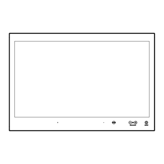
User Controls USER CONTROLS OVERVIEW The units are designed using Glass Display Control™ (GDC) touch technology to allow interactivity adjusting brilliance (brightness) and control power on / off with the use of illuminated symbols. Note that these symbols are only visible (backlight illuminated) when suitable power is connected, except for the power symbol which has a white silk print to indicate its position on the front glass. - Page 45 User Controls Action Indicators: SERVICE = Reserved for future use, no built-in function defined. Brightness Adjust: Brilliance / Brightness adjustment of the displayed image is adjusted by touching the (-) or (+) illuminated symbols. The entire area of text and symbols are visible as long as the unit is powered. Note that only the (-) and (+) are touch sensitive while the “*”...
-
Page 46: On Screen Display (Osd) Menu Introduction
OSD Menu Overview On Screen Display (OSD) Menu Introduction The OSD menu consists of main menus and submenus which are very easy to navigate through. All functions are explained in-depth later in this user manual. Prior to using the OSD menu, you should be sure to familiarize yourself with how to physically access the menu, how to navigate up/down/left/right, how to modify values, exiting menus and more. -
Page 47: Osd Keycode / Osd Lock Mode
OSD Menu Overview OSD Keycode / OSD Lock Mode During use, a small requester may pop-up on screen asking you for a “Key Code”. This is a safety feature (due to ECDIS Compliance) that might be predefined in your setup. To quickly understand how to enter a code, navigate and finally access the underlying main menu, simply follow the illustration below. -
Page 48: Osd "Basic", "Advanced" & "Service" Menu Modes
OSD Menu Overview OSD “Basic”, “Advanced” & “Service” Menu modes Three OSD Modes are available. The “Basic” Menu mode offers easy and clear access to most commonly used functions. The “Advanced” Menu mode offers a more advanced menu with technical information and is suited for more technical minded users and the “Service”... - Page 49 OSD Menu Overview OSD Menu Structure In this table all functions within menus and their submenus are shown. Functions that begins with an asterix (*) and bold/red font color style indicates this function/menu is only available during “Advanced” menu mode or during Video CVBS fullscreen.
-
Page 50: Color Mode Settings
OSD Menu Overview Color Mode Settings Level 1 (Main Menu) Level 2 Level 3 Level 4 Level 5 Color Mode Settings > < Exit Color Temperature > < Exit 9300K 8000K (Default) 6500K Exit *User > < Exit Red > (Slider Bar 0~255) Green >... -
Page 51: Osd Miscellaneous
OSD Menu Overview OSD Miscellaneous Level 1 (Main Menu) Level 2 Level 3 Level 4 Level 5 OSD Miscellaneous > < Exit OSD Position > < Exit OSD H. Position > (Slider Bar 0~255) OSD V. Position > (Slider Bar 0~255) Language >... -
Page 52: Management Settings
OSD Menu Overview Management Settings Level 1 (Main Menu) Level 2 Level 3 Level 4 Level 5 Management Settings > < Exit * Graphic Scaling > < Exit Graphic Scaling > Full Screen, Fill to Aspect Ratio, One To One Zoom >... -
Page 53: Service Settings
OSD Menu Overview Service Settings Level 1 (Main Menu) Level 2 Level 3 Level 4 Level 5 Service Settings > < Exit Video Scaler Firmware Ver > (Text Displayed) uC Firmware > (Text Displayed) Elapsed Time > (Text Displayed) Current Temp > (Text Displayed) *Fault Status >... -
Page 54: On Screen Display (Osd) Menu Functions
OSD Menu Functions On Screen Display (OSD) Menu Functions The following section covers all possible settings that the user can (in a certain mode) encounter or needs to adjust via easy understandable menus, text and navigation. For simpler reading the menu choice "Exit" has been left out of description in this chapter intentionally. - Page 55 OSD Menu Functions Input Source Settings - DVI-I1 Mode |---2--- This OSD setting item is used to select the DVI-I1 port operating mode. Settings as follows: DVI Mode = The port is locked to DVI-D mode, only accepting digital input. "Analog RGB1"...
- Page 56 OSD Menu Functions Input Source Settings - Rename Source |---2--- By factory default, every signal source input are named based on it’s signal property as described in the previous functions, but with the rename source function you can rename these into more understandable descriptions like;...
- Page 57 OSD Menu Functions Image Settings Lets you configure various visual preferences for any signal. The contents of these submenu are listed below. Image Settings - Auto Position |---2--- Will automatically fit the currently displayed full screen signal and center it based on the active area of the TFT display.
- Page 58 OSD Menu Functions Image Settings - Hue *Available in "Advanced" only + Video Fullscreen |---2--- Allows you to adjust/shift the main color properties of all Red, Green, Blue and Yellow (unique hues) values. This can be useful for certain Composite Video sources (no effect on DVI/DP/VGA signals) whose output may have shifted or seems to be "out of phase", where for instance blue seems more dominant than green, red and yellow-ish colors.
- Page 59 OSD Menu Functions Image Settings - Display - Clock |--------3-------- Adjust the horizontal frequency (clock) of the analog signal to improve visibility of the entire image. When it is adjusted, you will notice that the image will appear to be stretched and might in some situations start to flicker/scroll, at which point you must reverse the last adjustment to stop it from flickering/scrolling anymore.
- Page 60 OSD Menu Functions Image Settings - Video Setup *Available when Video Fullscreen only |---2--- Provides submenus where the following settings for Composite video signals are available: Image Settings - Video Setup - Main MADI mode |--------3-------- Motion Adaptive De-Interlacing. Motion adaptive de-interlacing is a pixel-based two-phase process.
- Page 61 OSD Menu Functions Image Settings - Video Setup - Noise Reduction - MPEG NR Mode |-------------4------------- MPEG NR (the generic coding of moving pictures and associated audio information) can be set to either "ON" or "OFF". This function will try to reduce noise as result from compressed/formatted MPEG video streams.
- Page 62 OSD Menu Functions Color Mode Settings Lets you adjust the color temperature (Kelvin degrees) of the image. This applies to the Main Source signal. Window overlays (PIP/PBP) and the OSD Menu overlay will be unaffected. Lower values make the image appear warmer, while higher values will make it appear cooler.
- Page 63 OSD Menu Functions Multi-PIP Settings Lets you adjust how the Picture-in-Picture (PIP) or Picture-by-Picture (PBP) display modes are set up. The default position of the rectangle is set to the upper left corner of the Active Display area. Note that this requires a valid incoming signal to be present in any of the "DVI", "DisplayPort", "VGA"...
- Page 64 OSD Menu Functions Multi-PIP Settings - PIP Display *Available only when PIP Mode on |---2--- When PIP Child mode is active, the size and position of the rectangle displaying the Secondary Source can be adjusted via the submenus below. Secondary Source needs to be a valid signal source.
- Page 65 OSD Menu Functions Multi-PIP Settings - PIP Picture |---2--- When PIP mode is active, the picture appearance of the Secondary Source can be adjusted via the following settings: Settings as follows: "Brightness" = Adjust the black level (brightness) of the Secondary Source, values from 0 to 255.
- Page 66 OSD Menu Functions OSD Miscellaneous Allows you to customize the visual appearance of the On Screen Display (OSD) menu, such as; position, transparency, time-out, assign hot keys, define access modes and save, load and recall favourite settings and more. The contents of these submenus are listed below. OSD Miscellaneous - OSD Position |---2---...
- Page 67 OSD Menu Functions OSD Miscellaneous - Preset Save - Save |--------3-------- Allows you to save current state of all function and values to user defined presets. The contents of the submenu is listed below. Settings as follows: "User 1" = Save all OSD settings to User 1 slot. "User 2"...
- Page 68 OSD Menu Functions OSD Miscellaneous - OSD Mode |---2--- Configuring the OSD Menu access based on most common functions to service/troubleshooting. Settings as follows: “Basic” = A few functions is not visible/available in this state. For most uses this is the preferred setting and are safe for the display functionality and continuous trusted operation on the unit.
- Page 69 OSD Menu Functions OSD Miscellaneous - Hot Key Assignment *Available in "Advanced/Service" mode only |---2--- Assign a commonly used OSD menu function to the available touch enabled Hot Keys which are located on the front of unit (user controls). The following functions are available to assign and most of them have a negative and positive counting logic.
- Page 70 OSD Menu Functions OSD Miscellaneous - OSD Key Outdoor *Available in "Advanced/Service" mode only |---2--- To prevent accidental activation of Glass Display Control™ (GDC) touch functions, you can add an extra layer of security on how "sensitive" the touch detection operates. This applies for "MENU", "(-) Brilliance (+)"...
- Page 71 OSD Menu Functions Management Settings Allows you to adjust overall settings for interaction/communication for the unit, such as scaling, zoom, timing of signals, sensitivity for the touch control, VGA filter and Serial/Ethernet communication and more. The contents of these submenus are listed below. Management Settings - Graphic Scaling *Available in "Advanced"...
- Page 72 OSD Menu Functions Management Settings - Graphic Scaling - Horizont Stretch |--------3-------- All stretching will performed from center of active display area and outwards in one direction. Settings as follows: "Horizont Stretch" = Zoom/stretch current full screen signal in Horizontal direction only (left and right).
- Page 73 OSD Menu Functions Management Settings - Unknown Timing Search *Available in "Advanced" mode only |---2--- Use this if you are unable to find or detect the incoming full screen signal automatically (applies for Analog VGA and CVBS video signals only. A PIP or PBP configured signal is not supported). It may be a customized signal regarding resolution and refresh frequency.
- Page 74 OSD Menu Functions Management Settings - Unknown Timing Search - Save Timing |--------3-------- The current "Timing Table Data" that is currently visible in the "Blind Mode" or via the "Auto Mode" functions may now be saved to a user defined slot. Available save slots from 1 to 8. Saving "Time Table Data"...
- Page 75 OSD Menu Functions Management Settings - Communication *Available in "Advanced" mode only |---2--- The unit allows for remote control (adjust brightness for example) and/or accessing internal information about the unit such as typenumber, serial number and more. To setup this feature, you first need to configure the Serial, Ethernet or USB protocol properly to match your external equipment specifications.
- Page 76 OSD Menu Functions Management Settings - Power Plan *Available in "Advanced" mode only |---2--- This setting will allow you to control the power mode of USB/VGA out and Ethernet port in Power off mode. Settings as follows for "VGA Out/USB in Off Mode": "Enable"...
- Page 77 OSD Menu Functions Management Settings - External Power Button *Available in "Advanced" mode only |---2--- This setting will allow you to manually enable the use of an external power button to turn off the Display unit. Please review the Pinout Assignments (Potmeter Control 9-pin DSUB MALE Connector) for connectivity.
- Page 78 OSD Menu Functions Service Settings Will show various technical and unit related information, such as; Firmware versions, Elapsed Time, Internal Temperature, Fault Status and activation for the internal Test Pattern image useful for trouble- shooting. Some of these functions are static information while others are accessible. Whenever you are in contact with helpdesk or service, they might require you to read back some of these values in order to precisely pinpoint any problem/question you should have with the unit or its functionality.
- Page 79 OSD Menu Functions Service Settings - Test Pattern |---2--- Will show the internal test pattern with greyscales, colors and raster patterned boxes to check for deviations in the TFT panel/display controller behaviour. It is independent of any current resolution or specifications found in the signal inputs. The test pattern is generated internally in the display controller and is sent 1:1 directly to the TFT panel.
- Page 80 This page left intentionally blank IND100130-2...
-
Page 81: Operation Advanced (Ddc/Ci)
Operation Advanced (DDC/CI) IND100130-2... -
Page 82: Introduction
Operation Advanced (DDC/CI) Control Overview Introduction DDC/CI (Display Data Channel/Command Interface) specifies a means for a computer to send commands to the unit's Display Video Controller to programmatically adjust parameters of the display instead of pressing physical buttons or navigate through an OSD menu. Specific commands to control units are defined in a separate official Monitor Control Command Set (MCCS) industry standard. - Page 83 Operation Advanced (DDC/CI) Control Overview Description Syntax and Functionality Details and Values Via SCOM Color Mode: = Command ID MCC: Set/Write Color Temperature: Kelvin Color Where Write ww xx (Color [S] <6E:w> 51 84 03 ww xx Temperature 05 A9 = 6500 Temperature Reply of successfull request:...
- Page 84 Operation Advanced (DDC/CI) Control Overview Description Syntax and Functionality Details and Values Via SCOM Touch Power Mode = Command ID MCC: Write/Set Power Mode: Where (0xE6) (Touch Power [S] <6E:w> 51 84 03 Mode) Reply of successfull request: 0xFF = Always Active [S] <6F:r>...
-
Page 85: Specifications
Specifications IND100130-2... -
Page 86: Specifications - Hd 15T22 Mmd-Xxx-Fxxx
Specifications - HD 15T22 MMD-xxx-Fxxx SPECIFICATIONS Note: All specifi cations are subject to change without prior notice! Please visit www.hattelandtechnology.com for the latest electronic version. All specifications are subject to change without prior notice! TFT Technology: Physical Considerations: • High Quality TFT with LED Backlight Technology •... -
Page 87: Specifications - Hd 15T22 Mmd-Xxx-Fhxx
Specifications - HD 15T22 MMD-xxx-FHxx SPECIFICATIONS Note: All speci cations are subject to change without prior notice! Please visit www.hattelandtechnology.com for the latest electronic version. All specifications are subject to change without prior notice! TFT Technology: Physical Considerations: • High Quality TFT with LED Backlight Technology Product Dimensions and Weight: •... -
Page 88: Specifications - Hd 17T22 Mmd-Xxx-Fxxx
Specifications - HD 17T22 MMD-xxx-Fxxx SPECIFICATIONS Note: All speci cations are subject to change without prior notice! Please visit www.hattelandtechnology.com for the latest electronic version. All specifications are subject to change without prior notice! TFT Technology: Physical Considerations: • High Quality TFT with LED Backlight Technology Product Dimensions and Weight: •... -
Page 89: Specifications - Hd 17T22 Mmd-Xxx-Fhxx
Specifications - HD 17T22 MMD-xxx-FHxx SPECIFICATIONS Note: All speci cations are subject to change without prior notice! Please visit www.hattelandtechnology.com for the latest electronic version. All specifications are subject to change without prior notice! TFT Technology: Physical Considerations: • High Quality TFT with LED Backlight Technology Product Dimensions and Weight: •... -
Page 90: Specifications - Hd 19T22 Mmd-Xxx-Fxxx
Specifications - HD 19T22 MMD-xxx-Fxxx SPECIFICATIONS Note: All specifi cations are subject to change without prior notice! Please visit www.hattelandtechnology.com for the latest electronic version. All specifications are subject to change without prior notice! TFT Technology: Physical Considerations: • High Quality TFT with LED Backlight Technology Product Dimensions and Weight: •... -
Page 91: Specifications - Hd 19T22 Mmd-Xxx-Fhxx
Specifications - HD 19T22 MMD-xxx-FHxx SPECIFICATIONS Note: All speci cations are subject to change without prior notice! Please visit www.hattelandtechnology.com for the latest electronic version. All specifications are subject to change without prior notice! TFT Technology: Physical Considerations: • High Quality TFT with LED Backlight Technology Product Dimensions and Weight: •... -
Page 92: Specifications - Hd 24T22 Mmd-Xxx-Fxxx
Specifications - HD 24T22 MMD-xxx-Fxxx SPECIFICATIONS Note: All speci cations are subject to change without prior notice! Please visit www.hattelandtechnology.com for the latest electronic version. All specifications are subject to change without prior notice! TFT Technology: Physical Considerations: • LED Backlight Technology, TFT Active-matrix Product Dimensions and Weight: •... -
Page 93: Specifications - Hd 24T22 Mmd-Xxx-Fhxx
Specifications - HD 24T22 MMD-xxx-FHxx SPECIFICATIONS Note: All speci cations are subject to change without prior notice! Please visit www.hattelandtechnology.com for the latest electronic version. All specifications are subject to change without prior notice! TFT Technology: Physical Considerations: • LED Backlight Technology, TFT Active-matrix Product Dimensions and Weight: •... -
Page 94: Specifications - Hd 24T23 Mmd-Xxx-Fxxx
Specifications - HD 24T23 MMD-xxx-Fxxx SPECIFICATIONS Note: All speci cations are subject to change without prior notice! Please visit www.hattelandtechnology.com for the latest electronic version. All specifications are subject to change without prior notice! TFT Technology: Physical Considerations: • LED Backlight Technology, TFT Active-matrix Product Dimensions and Weight: •... -
Page 95: Specifications - Hd 26T22 Mmd-Xxx-Fxxx
Specifications - HD 26T22 MMD-xxx-Fxxx SPECIFICATIONS Note: All specifi cations are subject to change without prior notice! Please visit www.hattelandtechnology.com for the latest electronic version. All specifications are subject to change without prior notice! TFT Technology: Physical Considerations: • LED Backlight Technology, TFT Active-matrix •... -
Page 96: Specifications - Hd 27T22 Mmd-Xxx-Fxxx
Specifications - HD 27T22 MMD-xxx-Fxxx SPECIFICATIONS Note: All speci cations are subject to change without prior notice! Please visit www.hattelandtechnology.com for the latest electronic version. All specifications are subject to change without prior notice! TFT Technology: Physical Considerations: • LED Backlight Technology, Color Active Matrix Product Carton Size and Weight: •... -
Page 97: Technical Drawings
Technical Drawings IND100130-2... -
Page 98: Technical Drawings - Hd 15T22 Mmd-Xxx-Fxxx
Technical Drawings - HD 15T22 MMD-xxx-Fxxx IND100132-309... -
Page 99: Technical Drawings - Hd 15T22 Mmd-Xxx-Fhxx
Technical Drawings - HD 15T22 MMD-xxx-FHxx High Bright model IND100132-338... -
Page 100: Technical Drawings - Hd 17T22 Mmd-Xxx-Fxxx
Technical Drawings - HD 17T22 MMD-xxx-Fxxx IND100132-310... - Page 101 Technical Drawings - HD 17T22 MMD-xxx-Fxxx HW00 Model IND100132-310...
-
Page 102: Technical Drawings - Hd 17T22 Mmd-Xxx-Fhxx
Technical Drawings - HD 17T22 MMD-xxx-FHxx High Bright model IND100132-339... - Page 103 Technical Drawings - HD 17T22 MMD-xxx-FHxx High Bright - HW00 Model IND100132-339...
-
Page 104: Technical Drawings - Hd 19T22 Mmd-Xxx-Fxxx
Technical Drawings - HD 19T22 MMD-xxx-Fxxx IND100132-311... -
Page 105: Hw00 Model
Technical Drawings - HD 19T22 MMD-xxx-Fxxx HW00 Model IND100132-311... -
Page 106: Technical Drawings - Hd 19T22 Mmd-Xxx-Fhxx
Technical Drawings - HD 19T22 MMD-xxx-FHxx High Bright model IND100132-337... -
Page 107: High Bright - Hw00 Model
Technical Drawings - HD 19T22 MMD-xxx-FHxx High Bright - HW00 model IND100132-337... -
Page 108: Technical Drawings - Hd 24T22 Mmd-Xxx-Fxxx
Technical Drawings - HD 24T22 MMD-xxx-Fxxx IND100132-312... -
Page 109: Hw00 Model
Technical Drawings - HD 24T22 MMD-xxx-Fxxx HW00 Model IND100132-312... -
Page 110: Technical Drawings - Hd 24T22 Mmd-Xxx-Fhxx
Technical Drawings - HD 24T22 MMD-xxx-FHxx High Bright model IND100132-336... -
Page 111: High Bright - Hw00 Model
Technical Drawings - HD 24T22 MMD-xxx-FHxx High Bright - HW00 Model IND100132-336... -
Page 112: Technical Drawings - Hd 24T23 Mmd-Xxx-Fxxx
Technical Drawings - HD 24T23 MMD-xxx-Fxxx IND100132-513... -
Page 113: Hw00 Model
Technical Drawings - HD 24T23 MMD-xxx-Fxxx HW00 Model IND100132-513... -
Page 114: Technical Drawings - Hd 26T22 Mmd-Xxx-Fxxx
Technical Drawings - HD 26T22 MMD-xxx-Fxxx IND100132-313... -
Page 115: Hw00 Model
Technical Drawings - HD 26T22 MMD-xxx-Fxxx HW00 Model IND100132-313... -
Page 116: Technical Drawings - Hd 27T22 Mmd-Xxx-Fxxx
Technical Drawings - HD 27T22 MMD-xxx-Fxxx IND100132-314... -
Page 117: Hw00 Model
Technical Drawings - HD 27T22 MMD-xxx-Fxxx HW00 Model IND100132-314... - Page 118 This page left intentionally blank IND100130-2...
-
Page 119: Technical Drawings - Accessories
Technical Drawings - Accessories IND100130-2... -
Page 120: Technical Drawings - Hd Tmb Sx2-A1
Technical Drawings - HD TMB SX2-A1 Desktop/Table Mounting Bracket 15 inch IND100132-315... -
Page 121: Technical Drawings - Hd Tmb Sx2-A1
Technical Drawings - HD TMB SX2-A1 Desktop/Table Mounting Bracket 17 inch IND100132-367... -
Page 122: Technical Drawings - Hd Tmb Sx2-A1
Technical Drawings - HD TMB SX2-A1 Desktop/Table Mounting Bracket 19 inch IND100132-368... -
Page 123: Technical Drawings - Hd Tmb Sx1-C1
Technical Drawings - HD TMB SX1-C1 Desktop/Table Mounting Bracket 24/26/27 inch IND100132-265... -
Page 124: Desktop/Table Mounting Bracket 24 Inch
Technical Drawings - HD TMB SX1-C1 Desktop/Table Mounting Bracket 24 inch IND100132-265... -
Page 125: Desktop/Table Mounting Bracket 26 Inch
Technical Drawings - HD TMB SX1-C1 Desktop/Table Mounting Bracket 26 inch IND100132-265... - Page 126 Technical Drawings - HD TMB SX1-C1 Desktop/Table Mounting Bracket 27 inch IND100132-265...
-
Page 127: Technical Drawings - Hd Cmb Sx2-A1
Technical Drawings - HD CMB SX2-A1 Console Mount Bracket IND100132-325... -
Page 128: Technical Drawings - Hd Cmb Sx2-A1
Technical Drawings - HD CMB SX2-A1 Console Mount Kit 15 inch IND100132-369... -
Page 129: Technical Drawings - Hd Cmb Sx2-A1
Technical Drawings - HD CMB SX2-A1 Console Mount Kit 17 inch IND100132-370... -
Page 130: Technical Drawings - Hd Cmb Sx2-A1
Technical Drawings - HD CMB SX2-A1 Console Mount Kit 19 inch IND100132-371... -
Page 131: Technical Drawings - Hd Cmb Sx2-E1
Technical Drawings - HD CMB SX2-E1 Console Mount Kit 24 inch IND100132-323... -
Page 132: Console Mounting 24 Inch
Technical Drawings - HD CMB SX2-E1 Console Mounting 24 inch IND100132-323... -
Page 133: P006801-1 Flush Mounting 24 Inch
Technical Drawings - HD CMB SX2-E1 P006801-1 Flush Mounting 24 inch IND100132-323... -
Page 134: Technical Drawings - Hd Cmb Sx2-F1
Technical Drawings - HD CMB SX2-F1 Console Mount Kit 26 inch IND100132-322... -
Page 135: Console Mounting 26 Inch
Technical Drawings - HD CMB SX2-F1 Console Mounting 26 inch IND100132-322... -
Page 136: P007084-1 Flush Mounting 26 Inch
Technical Drawings - HD CMB SX2-F1 P007084-1 Flush Mounting 26 inch IND100132-322... -
Page 137: Technical Drawings - Hd Cmb Sx2-E1
Technical Drawings - HD CMB SX2-E1 Console Mount Kit 27 inch IND100132-324... -
Page 138: Console Mounting 27 Inch
Technical Drawings - HD CMB SX2-E1 Console Mounting 27 inch IND100132-324... -
Page 139: P020721 - Flush Mounting 27 Inch
Technical Drawings - HD CMB SX2-E1 P020721 - Flush Mounting 27 inch IND100132-324... -
Page 140: Technical Drawings - Hd Ved Sx2-A1
Technical Drawings - HD VED SX2-A1 VESA Adapter 15 inch IND100132-316... -
Page 141: Technical Drawings - Hd Ved Sx2-B1
Technical Drawings - HD VED SX2-B1 VESA Adapter 17 inch IND100132-317... -
Page 142: Technical Drawings - Hd Ved Sx2-C1
Technical Drawings - HD VED SX2-C1 VESA Adapter 19 inch IND100132-318... -
Page 143: Technical Drawings - Hd Ved Sx2-I1
Technical Drawings - HD VED SX2-I1 VESA Adapter 24 inch IND100132-384... -
Page 144: Technical Drawings - Hd Ved Sx2-J1
Technical Drawings - HD VED SX2-J1 VESA Adapter 26 inch IND100132-385... -
Page 145: Technical Drawings - Hd Ved Sx2-K1
Technical Drawings - HD VED SX2-K1 VESA Adapter 27 inch IND100132-386... -
Page 146: Technical Drawings - Jh 15Tap Std-C1
Technical Drawings - JH 15TAP STD-C1 15 inch Series X to fit 15 inch Series 1 Console Cutout IND100132-272... -
Page 147: Technical Drawings - Jh 19Tap Std-C1
Technical Drawings - JH 19TAP STD-C1 19 inch Series X to fit 19 inch Series 1 Console Cutout IND100132-273... -
Page 148: Technical Drawings - Hd 19Tap Sx2-C2
Technical Drawings - HD 19TAP SX2-C2 19 inch Series X to fit 19 inch Series 2 Console Cutout IND100132-340... - Page 149 Technical Drawings - HD 19TAP SX2-C2 19 inch Series X to fit 19 inch Series 2 Console Cutout IND100132-340...
-
Page 150: Technical Drawings - Jh 26Tap Std-A1
Technical Drawings - JH 26TAP STD-A1 26 inch Series X to fit 26 inch Series 1 Console Cutout IND100132-275... -
Page 151: Technical Drawings - Hd 26Tap Sx1-A1
Technical Drawings - HD 26TAP SX1-A1 26 inch Series X to fit 27 inch Series 1 Console Cutout IND100132-389... -
Page 152: Technical Drawings - Hd 15Cov Sx1-A1
Technical Drawings - HD 15COV SX1-A1 UV Sun Cover (15 inch) IND100132-295... -
Page 153: Technical Drawings - Hd 17Cov Sx1-A1
Technical Drawings - HD 17COV SX1-A1 UV Sun Cover (17 inch) IND100132-296... -
Page 154: Technical Drawings - Hd 19Cov Sx1-A1
Technical Drawings - HD 19COV SX1-A1 UV Sun Cover (19 inch) IND100132-297... -
Page 155: Technical Drawings - Hd 24Cov Sx1-A1
Technical Drawings - HD 24COV SX1-A1 UV Sun Cover (24 inch) IND100132-298... -
Page 156: Technical Drawings - Hd 26Cov Sx1-A1
Technical Drawings - HD 26COV SX1-A1 UV Sun Cover (26 inch) IND100132-342... -
Page 157: Technical Drawings - Hd 27Cov Sx1-A1
Technical Drawings - HD 27COV SX1-A1 UV Sun Cover (27 inch) IND100132-343... -
Page 158: Technical Drawings - Hd Cak Sx2-A1
Technical Drawings - HD CAK SX2-A1 Front Console Mounting/Adapter Kit (24 inch) IND100132-401... -
Page 159: Technical Drawings - Hd Cak Sx2-B1
Technical Drawings - HD CAK SX2-B1 Front Console Mounting/Adapter Kit (27 inch) IND100132-402... -
Page 160: Technical Drawings - P006997-1
Technical Drawings - P006997-1 IP66 Panel Gasket (15 inch) IND100132-335... -
Page 161: Technical Drawings - P007130-1
Technical Drawings - P007130-1 IP66 Panel Gasket (17 inch) IND100132-334... -
Page 162: Technical Drawings - P007131-1
Technical Drawings - P007131-1 IP66 Panel Gasket (19 inch) IND100132-333... -
Page 163: Technical Drawings - P022211
Technical Drawings - P022211 IP66 Panel Gasket (24 inch) IND100132-432... -
Page 164: Technical Drawings - P007178
Technical Drawings - P007178 IP66 Panel Gasket (26 inch) IND100132-332... -
Page 165: Technical Drawings - P018743
Technical Drawings - P018743 IP66 Panel Gasket (27 inch) IND100132-292... -
Page 166: Technical Drawings - Hd Rem Sx1-A1
Technical Drawings - HD REM SX1-A1 For External Mounting IND100132-287... -
Page 167: Appendixes
Appendixes IND100130-2... -
Page 168: Uhf Interference Prevention
V2 Firmware Update User Instruction tellectual properties belong to Hatteland Technology AS DOC206316-1 - Revision 9 UHF Interference Prevention Note: Information below is an excerpt from original document located on Engineering Change Notification: 5.3 Glass Display Controller Calibration https://www.hattelandtechnology.com/product-notifications/series-x-g2-maritime-multi-display-mmd-firmware-update-24_2020_ecn To calibrate the GDC (Glass display controller) to be better able to distinguish between UHF interference and a finger press on the “buttons”, the GDC must be calibrated and please follow these steps. - Page 169 GEV2 Firmware Update User Instruction All intellectual properties belong to Hatteland Technology AS DOC206316-1 - Revision 9 5.4 Turning on/off UHF protection mode (OSD Key Outdoor mode) To turn on/off the function for limiting the UHF interference on the Series X G2 Maritime Multi Displays, there are two ways of doing it.
-
Page 170: Pinout Assignments
Pinout Assignments Connectors illustrated here are either standard by factory default or may be available (through factory customization). Note that some combinations may not be possible due to space restrictions. List also valid for customized models. All pin out assignments are seen from users Point of View (POV) while looking straight at the connector. Please review the dedicated datasheet or technical drawings for your actual unit to identify and determine the presence of desired connector. - Page 171 Pinout Assignments 9-pin DSUB Male Warning: Do not connect or disconnect cables/connectors to 4 3 2 1 this connector while the Display Extern unit is powered on. Failure to do so may result in damaged electronics inside the Display Unit. A short on wires may cause system to restart.
- Page 172 Pinout Assignments Serial COM RS-232 non-isolated, 9-pin DSUB Female USER-External dimming buttons 9-pin DSUB Male 4 3 2 1 External dimming buttons must be of “Push Button” type. Push or push and hold down for dimming. 4 3 2 1 9 8 7 6 PIN 01** BUZ+ Buzzer Control Positive IN*...
- Page 173 Pinout Assignments 10-pin RS-422 / RS-485 Module 8-pin RJ45 10/100/1000Mbps LAN/Ethernet “RS-422/RS-485 SCOM + Buzzer” (Internal Buzzer can be controlled externally) 1 2 3 4 5 6 7 8 PIN 01 D0P+ Diff erential Pair 0 (Positive) 2 4 6 8 10 1 3 5 7 9 PIN 02 D0N- Diff erential Pair 0 (Negative)
-
Page 174: Iec62368 Policy For Hatteland Technology Products
IEC62368 policy for Hatteland Technology products Introduction According to the requirements of EN 62368-1:2014. The tables below refers to the policies for opening, servicing and installation of the unit(s) referred to in this manual. This equipment is designed to be used as a fixed installation and to be sold through special sales channels for professional use. - Page 175 IEC62368 policy for Hatteland Technology products Authority Description Children This equipment is not suitable for use in locations where children are likely to be present. Ordinary person/ Not allowed to open unit. Sailor/End-User Not allowed to install the unit. Not allowed to terminate/connect cables to the unit. Instructed person Allowed to open hatches/latches which does not require tools, such as Disktrays.
-
Page 176: Basic Trouble-Shooting
Basic Trouble-shooting GENERAL ISSUES FOR TFT PANEL BASED PRODUCTS Note: Applies for a range of various products. This is only meant as a general guide. O PICTURE / LED BEHAVIOUR: If there is no light at all in the LED at the FRONT, check power cables. If the LED in front is green, then check if the brightness is set/adjusted to max brightness. -
Page 177: Declaration Of Conformity
Declaration of Conformity We, manufacturer, Hatteland Technology AS, Eikeskogvegen 52, N-5570 Aksdal, Norway declare under our sole responsibility that the JH MMD, JH MMC, JH STD, JH MIL, HM NMD, HM MIL, HM CMD, HT STD, HD MMD, HD MVD, HM MMD, HM XRD, HM RMD, HT MMC, HD MMC, HT/HM (Computers), HN G (Network Switches) and HT xxx (Accessories/Peripherals) product ranges is in conformity with the following standards in accordance with the EMC Directive. -
Page 178: Return Of Goods Information
Return Of Goods Information Return of goods: (Applies not to warranty/normal service/repair of products) Hatteland Technology referenced as “manufacturer” in this document. Before returning goods, please contact your system supplier before sending anything directly to manufacturer. When you return products after loan, test, evaluation or products subject for credit, you must ensure that all accessories received from our warehouse are returned. -
Page 179: General Terms And Conditions
General Terms and Conditions As of January 2015, Hatteland Technology AS’ “Terms of Sales and Delivery” and “Warranty Terms” have been substituted by the updated ”General terms and conditions for sale of goods and performance of additional services” (the “General Terms and Conditions”). Further, from January 2015 onward, the previous “Terms of Sales and Delivery”... -
Page 180: Pixel Defect Policy
Pixel Defect Policy PIXEL DEFECT POLICY Dot-defects (Bright or dark spots on the panel) Due to the effect that dot failures are part of the TFT technology such failure occurrence cannot be prevented basically. Even though dot defects usually occur during production process, new defects can appear within the lifespan of a TFT display. Neither the production at LCD-supplier nor the use of an LCD-Monitor after shipment can be influenced by Hatteland Technology. -
Page 181: Parts And Recycling
Parts and Recycling Rev 02 - 20 May 2021 Parts in Displays and Panel Computers, and how to recycle Part Where to dispose of parts TFT Panel Electrical waste Optically bonded units: the TFT Panel, Glass Metal waste Glass and frame is to be disposed of as Electrical waste. -
Page 182: Notes
Notes General Notes: - The unit is tested according to IEC 60945 4th (EN 60945:2002), 4.4, equipment category b) “protected from the weather (formerly class B)”. - Other type approvals applies for the different products. Please see the appropriate “Specifications” page in this manual for more information. - Use of brillance and Glass Display Control™... - Page 183 User Notes Appendix IND100077-24...
-
Page 184: Revision History
Revision History Rev. Date Notes 00_01 09 Jun 2017 Release for internal review. 00_02 15 Jun 2017 Added Panel Gaskets 00_03 18 Aug 2017 Revised after internal review, added HB models and more accessories 23 Oct 2017 Final version 01 for internet release Note: Address changed from ”Stokkastrandvegen 87B, N-5578 Nedre Vats”... - Page 185 Revision History 02 Dec 2019 Removed Global and Docmentation Driver DVD from Contents of Package, page 8, ref: https://www.hatteland-display.com/mails/20_2019_eol.html Adjusted OSD menus according to: https://www.hatteland-display.com/mails/13_2019_ecn.html Serveral corrections regarding OSD Menu modes/header made throughout the OSD Menu chapter Replaced P007032-1 Gasket 24” with P022211, page 9,146 Added information about “UHF Protection”, page 67 03 Feb 2020 Replaced DDC/CI Chapter with the appropriate section intended for Series X G2 MMD models, page 78-80...
- Page 186 Revision History Appendix IND100077-170...
- Page 187 Hatteland Technology AS | www.hattelandtechnology.com | Enterprise no: NO974533146...
Need help?
Do you have a question about the Hatteland Technology HD 15T22 MMD F Series and is the answer not in the manual?
Questions and answers