
Related Manuals for emaux CTRL2-5L


Summary of Contents for emaux CTRL2-5L
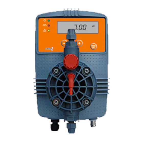
- Page 1 CTRL2 - 5L / CTRL2 - 7L SERIES DUAL PARAMETER PH-RX MICROCONTROLLER SOLENOID DRIVEN DOSING PUMP OPERATING INSTRUCTIONS AND MAINTENANCE EMPU12053149...
- Page 2 INDEX page 3 CTRL2 DOSING PUMPS MAIN COMPONENTS page 3 USER INFORMATION SIGNS page 4 1.0 – HINTS AND WARNING 1.1 - WARNING-SHIPPING AND TRANSPORTING-PROPER USE OF DOSING PUMP page 4 RISKS-TOXIC/DANGEROUS LIQUID HANDLING- ASSEMBLING AND DISMANTLING page 4 page 5 2.0 –...
-
Page 3: Hints And Warnings
1.6 - ASSEMBLING AND DISMANTLING THE EQUIPMENT 1.6.1 - ASSEMBLY All EMAUX equipments are supplied fully assembled. Please refer to exploded view drawings shown in the present booklet, showing all details and a complete overview of all components. These drawings are in any case useful whenever spare parts are needed. - Page 4 2.0 – CTRL - 2 SERIES DOSING PUMPS 2.1 – OPERATION PRINCIPLE The dosing pump is activated by a PTFE diaphragm mounted onto a piston operated by pulses received from the electromagnet. Return phase is spring operated. Control circuit is SMD (surface mounting device) with microcontroller technology, digital controls, displ ay and LED indicators for visualizing pump status.
-
Page 5: Technical Characteristics
2.4 - TECHNICAL CHARACTERISTICS CTRL2 - 7L Pump Max Flow / Max Pressure Start up* performance Frequency Stroke volume Pump head Valves type range imp/min cc(ml) / stroke type types CTRL2 - 7L 0,98 PP 3/8" Ball checks CTRL2 - 5L 0,69 PP 3/8"... -
Page 6: Parallel Connections
- try to use a power switch in order to have separate connections via contact relay or relay. - when this is not possible, contact EMAUX technical service. d. Install the pump as shown in fig.4 bearing in mind that: - ensure that max system pressure corre sponds to unit max pressure data (see performance curves). - Page 7 NOTE In case of priming difficulties: use a normal syringe to suck liquid from the discharge nipple while the pump is in operation (air bleed valve closed), continuing until you actually see the liquid rise in the syringe. Use a short piece of suction hose to connect the syringe to the discharge nipple (refer parag.”TROUBLESHOOTING”).
-
Page 8: Maintenance
15 to 30 seconds and without connecting the hose to the nipples; if it’s not possible, unscrew the pump head, empty it and then remount it. EMAUX provides a special liquid ends configuration for Sulphuric Acid or other aggressive chemicals. -
Page 9: Overall Dimensions
6.0 – WIRING SERVICE CONNECTORS FOR CTRL2 (fig.15) Always TURN PUMP OFF when servicing and wiring connectors !!! Fig.15 FEMALE SERVICE CONNECTOR WIRING DIAGRAM Functions descriptions CONNECTOR 1 Lev el switch connection (fig.15) Configurations Lev el switch Pin 1 = NO connection Pin 2 = NO connection Pin 3 = Level switch wire Pin 4 = Level switch wire... - Page 10 CTRL2 Fig.17 7.0 – DUAL PARAMETER DOSING PUMP AND PHRX CONTROLLER CTRL2 This unit is microcontroller based dosing pump incl udes both a dosing pumps and high tech controllers which features three parameters all in one enclosure: PH or RX (ORP). BENEFITS: reducing stock value against a great quality and versatility 7.1 - CTRL2 DIGITAL CONTROLS (fig.17) 1 - Enter button “OK”: confirms selection...
-
Page 11: Display Description
8.0 – DISPLAY DESCRIPTION Overdosing alarm Unit general settings OVER SETUP Delay after switching unit ON Switching-on delay settings DELAY STARTUP Set-point programming Reset activation SET POINT RESET Level alarm Intervention field selection LEVEL DIRECTION Alarms level setting Max Impulse / minute (frequency) ALARM MAX** Menu selection Basic/Full... -
Page 12: Keep In Mind
10.0 – PROGRAMMING CONTROLLER KEEP IN MIND: if no selection is made dusring set-up step, pump wil start to release pulse strokes 10.1 – PUMP SET UP / CONTROLLER SETTING The first operation is to select the required parameter intended to measure and control pH or RX (mV). Pump power ON, display will show last software revision and also the type of measurement parameter flashing (default setting: pH with operating menu BASE basic-simplified mode). -
Page 13: Measurement Type Selection
10.1 – MEASUREMENT TYPE SELECTION Once entered SETUP menu it’s possible to select the required type of measurement parameter. Default is to Pressing – and + buttons a loop menu is entered , user can select among 2 measurements parameters: pH or RX (mV). To confirm selection press OK The program will enter Password menu. - Page 14 11.0 – CALIBRATION To calibrate controller, user must adjust two calibration points: for pH two adjustable point for Redox (mV) one adjustable point 11.1 – CALIBRATION MENU To enter CALIBRATION menu from measuring mode press OK then + button, on display CALIB.
-
Page 15: Hysteresis Setting
12.2 – PROGRAMMING REDOX SET-POINT From measuring status, press OK, the program will move to SETPOINT programming. Press OK again, display will show mV flashing meaning that it can be adjusted to required set point. Using – or + buttons. Once selected required set point, press OK to confirm. - Page 16 13.4 – FLOW RATE FREQUENCY ADJUSTMENT – MAN (MANUAL ON-OFF) SETTI NG Selecting Manual mode (ON-OFF), pressing OK, program will move to Frequency adj ustment setting. User must set dosing pump flow rate selecting stroke s frequency range from 0 to 100%. Max frequency 120 imp/min.
- Page 17 15.1.1 – MAXIMUM ALARM SETTING Display shows and current measured value both flashing. Press – or + to select max measured value ALARM point Press OK to confirm 15.1.2 – MINIMUM ALARM SETTING Display shows min and current measured value both flashing. Press –...
- Page 18 17.0 – TROUBLE-SHOOTING FOR CTRL2 SERIES Operator must always protect itself w hen handling hazardous feed chemicals. Use googles and protectiv e clothing and follow the safety information sheets of chemical manufacturer. When remov ing the metering pump from the plant, be careful as there might be some residual additiv e in the discharge hose.
- Page 19 CTRL2-7L types 1,5-10 / 2,5-15 / 5,5-07 / 07-04: page then contact manufacturer CTRL2-5L types 01-05 / 2,5-06 / 05-04 / 07-02 Customer Service, Dealer or Distributor. Check that voltage is within +/- 10-15% of ⇒ PUMP PULSES ARE NOT CONSTANT rated voltage...
- Page 20 When this is not possible, an appropriate chemical mixer must be inserted between the injection point and the electrode. EMAUX EL ECT RODE HOL DERS FOR CTRL2-7L APPLICATIONS ECELL1 ECELL 4...
- Page 21 TYPICAL INSTALLATIONS CTRL2 SERIES TYPICAL INSTALLATIONS CTRL2 SERIES: PH or RX VERSION OFF-LINE ECELL1 ELECTRODE HOLDER VERSION IN-LINE ELECTRODE HOLDER A. Dosing pump J. Joint bracket floating level switch / filter B. Power supply cable K. Air bleed hose C. Service connectors output L.
-
Page 22: Exploded Views
20 point 4. H. FLAT SPRING I. WASHER J. NUT NOTE the above drawing shows the main components of a typical solenoid, however each type of performance could have extra components to keep in mind when contacting EMAUX customer service. - Page 23 PUMP HEAD EXPLODED VIEW STANDARD PP TYPE 1÷15 l/h STANDARD PUMP HEAD WITH BALL CHECKS 1. PUMP HEAD (PP standard 1÷15 l/h) * 2. AIR BLEED VALVE O-RING 3. BALL CHECK SEAT (air bleed) 4. BALL CHECK VALVE (air bleed) 5.
- Page 24 PVDF PUMP HEAD AGGRESSIVE CHEMICALS CONFIGURATION 1÷15 l/h PVDF PUMP HEAD WITH DOUBLE BALL CHECKS 1. PUMP HEAD (PVDF 1÷15 l/h) * 2. NIPPLE O-RING 3. SUCTION BALL CHECK ASSEMBLY* 4. BALL CHECK O-RING 5. HOSE ADAPTER PVDF 6. HOSE STOPPER PVDF 7.
- Page 25 PVDF AUTO BLEED PUMP HEAD 1÷15 l/h AIR BLEED SIDE PVDF AUTO BLEED PUMP HEAD WITH DOUBLE BALL CHECKS 1. PUMP HEAD (PVDF 1÷15 l/h) 2. NIPPLE O-RING 3. SUCTION BALL CHECK ASSEMBLY* 4. BALL CHECK O-RING DISCHARGE SIDE 5. HOSE ADAPTER PVDF 6.
- Page 26 PMMA PUMP HEAD EXPLODED VIEW FOR VISCOUS LIQUIDS 1÷20 l/h PMMA PUMP HEAD FOR VISCOUS LIQUIDS 1. PUMP HEAD 2. VALVE O-RING 3. BALL CHECK SEAT 4. BALL CHECK 5. VALVE ENCLOSER 6. BALL CHECK LIMITER 7. NIPPLE O-RING 8. NIPPLE 1/2” PP 9.
- Page 27 EXPLODED VIEWS VALVES AND NIPPLES EXPLODED VIEWS STANDARD BALL CHECK ASSEMBLY SUCTION DISCHARGE A. O-RING 106 6. BALL CHECK VALVE B. VALVE HOUSING 7. NIPPLE O-RING 2062 C. BALL CHECK 8. NIPPLE D. O-RING 2015 9. PROTECTION CAP E. O-RING 114 10.HOSE NUT Valid for CERAMIC STANDARD VALVE EQUIPPED...
- Page 28 FOOT VALVE - FILTER STANDARD FOOT VALVE / FILTER A. STRAINER B. FILTERING MEDIA C. STRAINER COVER D. FOOT VALVE* E. NIPPLE F. HOSE NUT Valid for LIP type valves in FPM (standard), EPDM, SILICON FOOT VALVE WITH HASTELLOY SPRING LOADED BALL CHECK VALVE / FILTER A.
- Page 29 DOSING PUMP ACCESSORIES QUICK REMOVABLE INJECTION LANCE QUICK REMOVABLE INJECTION LANCE guarantees clean and fast maintenance operations of the injection no- return valve. Furthermore allows the operator to adjust the length of the injection point inside the pipe of the system to treat thus set the injection point at the center of the pipe where the internal flow will guarantee better mixing.
- Page 30 MEASUREMENTS AND PROGRAMMING NOTES...
- Page 31 Emaux (Zhong Shan) Swimming Pool Equipment Co.,Ltd. Long Zhu Industrial Park, Nan Lang Industrial Area, Nam Lang Town, ZhongShan City, Guangdong Province, China Tel: (0760) 8552 7988 Fax: (0760) 8552 7188 Website: www.emaux.com.au Instructions booklet CTRL2 Version...
Need help?
Do you have a question about the CTRL2-5L and is the answer not in the manual?
Questions and answers