
Subscribe to Our Youtube Channel
Related Manuals for LEGRAND 4 226 81


Summary of Contents for LEGRAND 4 226 81
- Page 1 Automatic transfer switch 4 226 81 Installation and user manual L I N L I N 7 - 6 I E C Part. LE12710AA-01/21-01 GF...
-
Page 2: Automatic Transfer Switch
Automatic transfer switch 4 226 81 ITALIAN ENGLISH ENGLISH L I N L I N 7 - 6 I E C... - Page 3 • Before any device maintenance operation, remove the supply from measuring inputs or isolate them cutting the supply from other sources. • Legrand assumes no responsibility if the device isn’t properly used, if installative informations aren’t respected or if the device is tampered.
- Page 4 Index 1. General features Description Applications Installation 2. ATS front panel description Selection keys LEDs IR Input 3. Operating mode Reset mode (OFF-RESET) Manual mode (MAN) Automatic mode (AUT) 4. Power-up 5. Main menu 6. Password access 7. Display pages 8.
- Page 5 Automatic transfer switch 4 226 81 12. Parameters 12.1 Description of “utility” menu 12.2 Description of “general” menu 12.3 Description of “password” menu 12.4 Description of “Load changeover” menu 12.5 Description of “Voltage control line 1 S.Q1” menu 12.6 Description of “Voltage control line 2 S.Q2” menu 12.7...
-
Page 6: General Features
Otherwise it is necessary modify the configuration. Check the wiring diagram supplied by Legrand in order to correctly connect the unit and others Legrand devices. • The ATS standard configuration guarantees the correct work of devices if wiring diagrams supplied are respected. -
Page 7: Selection Keys
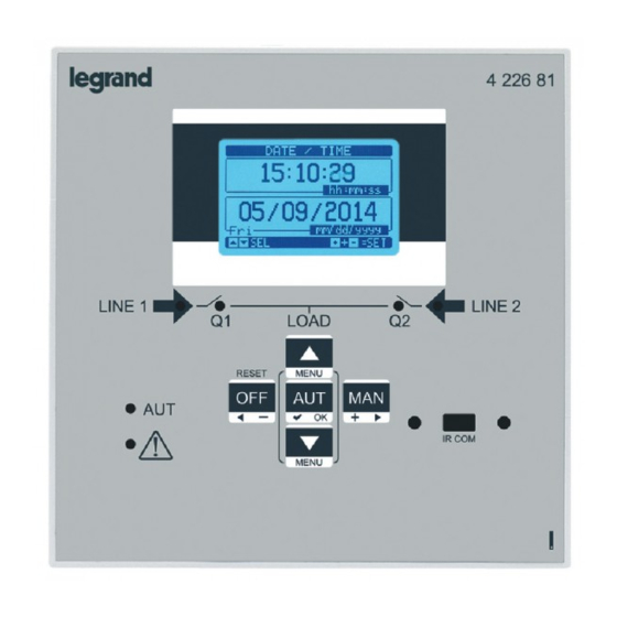
Automatic transfer switch 4 226 81 2. ATS front panel description Selection keys • OFF button (F) – It selects the OFF operating mode. Green AUT LED (D) lights (when selected). • AUT button (G) – It selects the automatic mode. -
Page 8: Operating Mode
3. Operating mode With of OFF-RESET/MAN/AUT keys the desiderated operating modes can be selected and they will appear on the display. Fig. 2 - OFF/RESET Fig. 3 - MAN Fig. 4 - AUT The change of operating mode can be done by pressing the specific button for at least 0.5s. After this time, the new cho- sen modality will appear another display. - Page 9 Automatic transfer switch 4 226 81 Voltage line 1 Voltage Line 2 Line 2 selected Page scroll locked Selectable function with MAN Fig. 9 - Generator manual mode Fig. 10 - Start Generator manual mode Automatic mode (AUT) • In automatic mode, the ATS checks permanently the lines and breakers status. Starting from the state of lines it performs autonomously the closing/opening operations of breakers and the optional startup/shutdown of the generator set.
- Page 10 5. Main menu • The “main menu” is made up of a group of graphic icons that allow to access to functions. In function of selected icon, a description will be displayed on the display. Fig. 11 - Main menu The main menu allow the rapid access to measurements and settings.
-
Page 11: Password Access
• To enable password management and to define numeric codes, see M03 “password” menu. • There are different access levels: • Password disabled (OFF)– The password is disabled. Complete access to all parameters (Default Legrand). • Password enabled (ON) – The password is enabled: - Access without to insert password (Lev.1) The password is enabled but not inserted. -
Page 12: Display Pages
7. Display pages Voltage S.Q1 Voltage S.Q2 (Device Q1) (Device Q2) Contact status Contact status device Q1 device Q2 Fig. 16 - Synoptic S.Q1 S.Q2 Measure unit Phases indication Operative Mode Frequency Fig. 17 - L-L voltage Voltage Phases indication Frequency Fig. - Page 13 Automatic transfer switch 4 226 81 Digital input Output status status Fig. 21 - Input/Output status Input function Fig. 22 - Inputs Output function Fig. 23 - Outputs Free user text Fig. 24 - Information page Fig. 25 - System info •...
- Page 14 8. Communication • The inputs and outputs are identified by a code and a sequence number. Example: the digital inputs are identified by code INPx, where x is the number of the input. In the same way, digital outputs are identified by code OUTx. CODE DESCRIPTION BASE...
- Page 15 Automatic transfer switch 4 226 81 User Alarms (UAx) • User can set a maximum of 4 programmable alarms (UA1…UA4). • Conditions that generates the alarm can be different: - In association of one thresholds LIMX set - Activation of digital inputs INPx.
-
Page 16: Keypad Lock
9. Keypad lock • The automatic transfer switch keypad can be locked, avoiding not desidered command. • Once the keypad is locked, it will only be possible to view measures, but not to change operating mode or to operate in If the icon menu is shown and the keypad is locked, wait 2 minutes to return to main MAN mode on devices. - Page 17 Automatic transfer switch 4 226 81 10. Programmation 10.2 Parameter setting (setup) with PC • The managing of setting parameters can be done also using the PC Software “ACU configurator” (available to free download on E-catalogue Legrand. • Using software ACU it is possible to transfer set-up parameters from ATS to PC, generating a file. It is also possible to transfer to ATS a file with parameters from SW ACU.
- Page 18 (available to free download on Google Play and Apple iStore). • The connection between ATS and App is possible by means of WiFi dongle (Legrand). • The App permits to see alarms, to send commands, to read measures, to set parameters, to download events.
- Page 19 Automatic transfer switch 4 226 81 11. Menu The following table lists shows the available ATS menus: CODE MENU DESCRIPTION UTILITY Language, brightness, display pages, etc. GENERAL System nominal data PASSWORD Password settings CHANGEOVER Load changeover settings LINE 1 CONTROL Valid limits for voltage line1 (S.Q1)
- Page 20 12. Parameters • • In menu “parameters” are described all parameters, their changes and it is defined the work mode of ATS. Menu is composed by 9 parts. • • Each menu is composed by specific parameters Px that can be modified in function of needs. •...
- Page 21 Automatic transfer switch 4 226 81 12.2 Description of “general” menu M02 - GENERAL DEFAULT RANGE P02.01 Nominal plant voltage 50-50000 P02.02 Phase sequence control L1-L2-L3 L3-L2-L1 P02.03 Wiring mode L1-L2-L3 L1-L2-L3-N L1-L2-L3 L1-N-L2 L1-N P02.04 Voltage control mode L-L + L-N P02.05 Nominal frequency...
- Page 22 12. Parameters 12.4 Description of “Load changeover” menu In the following menu are present mains parameters to identify the correct plant configuration and to define characteri- stics to manage and to check the changeover system. M05 – LOAD CHANGEOVER DEFAULT RANGE P05.01 Application type P05.02 Priority line selection...
- Page 23 Automatic transfer switch 4 226 81 • P05.06 – If, after sending an open or close command to a circuit breaker, this is not positioned correctly within this time (feedback by means of OC contacts), alarms A03 or A04 are generated.
- Page 24 12. Parameters 12.5 Description of “Voltage control line 1 S.Q1” menu In this paragraph control parameters, thresholds setting and control levels of power sources defining acceptability criteria are described. In this menu is also possible set the insensibility level to micro interruptions using parameter P06.10 (stan- dard value 100ms).
- Page 25 Automatic transfer switch 4 226 81 • P06.01 - P06.02 - P06.03 – The first two parameters define the minimum voltage threshold and the related hysteresis upon restore. P06.02 cannot be set to a lower value than P6.01. P6.03 defines the intervention delay of this protection.
- Page 26 12. Parameters 12.6 Description of “Voltage control line 2 S.Q2” menu M07 – VOLTAGE CONTROL LINE 2 S.Q2 DEFAULT RANGE P07.01 MIN voltage limit for trip 70-100 P07.02 MIN voltage restore 70-100 P07.03 MIN voltage delay 0-600 P07.04 MAX voltage limit for trip 100-130 / OFF P07.05 MAX voltage restore...
- Page 27 • P11.n.03 – It sets the state of the output when the function associated with the same is inactive: NOR = output de- energized, REV = output energized. The configuration installed on ATS by Legrand ensures the correct work if standard wiring diagrams supplied are respected. WARNING: the modify of parameters could generate incompatibility with supplied wiring diagrams. It is recommended to not modify the original configuration.
-
Page 28: Alarm Properties
12. Parameters 12.9 Description of “Alarms” menu • When an alarm is generated, the display will show an alarm icon, the code and the description of the alarm in the lan- guage selected. Fig. 36 • If the navigation keys in the pages are pressed, the pop-up window showing the alarm indications will disappear mo- mentarily, to reappear again after a few seconds. -
Page 29: Alarm Table
Automatic transfer switch 4 226 81 12.11 Alarm table CODE DESCRIPTION ● ● ● ● ● ● Timeout Q1 (line 1) ● ● ● ● ● ● Timeout Q2 (line 2) ● ● ● ● S.Q1 (line 1) wrong phase sequence ●... -
Page 30: Alarm Description
12. Parameters 12.12 Alarm description CODE DESCRIPTION ALARM EXPLANATION The Q1 changeover device did not perform the opening or clo- sing operation within the max. time set. After alarm A03 genera- Q1 (Line 1) timeout tion, the opening or closing command is inhibited. Alarms are generated only if at least one of the two power sources S.Q1 or S.Q2 are present. - Page 31 • See menu “M10 Programmable inputs” for more details. The configuration installed on ATS by Legrand ensures the correct work if standard wiring diagrams supplied are respected. WARNING: the modify of parameters could generate incompatibility with supplied wiring diagrams. It is recommended to not modify the original configuration.
-
Page 32: Output Function Table
13. Function I/O 13.2 Output function table The configuration installed on ATS by Legrand, ensures the correct work if standard wiring diagrams supplied are respected. WARNING: the modify of parameters could generate incompatibility with supplied wiring diagrams. It is recom- mended to not modify the original configuration. - Page 33 Automatic transfer switch 4 226 81 FUNCTION DESCRIPTION External S.Q2 control Line 2 voltage control signal from external device. Ena- bled, it indicates the voltage is within the limits Enable Load on S.Q1 It allows load connection on S.Q1, in addition to internal controls.
-
Page 34: Installation
Repeat the same operation for the four clips. • Tighten the fixing screw with a maximum torque of 0,5Nm. • In case it is necessary to dismount the system, unloose the screws. • For the electrical connection see the Legrand wiring diagrams. -
Page 35: Terminals Position
Automatic transfer switch 4 226 81 15. Terminals position CODE DESCRIPTION Line 1 voltage control (S Q1) Line 2 voltage control (S Q2) OUT1 - OUT7 B300 / 250V~ 8A AC1 / 1A 30V= PILOT DUTY OUT1 - OUT2 - (NO) Programmable relay... -
Page 36: Technical Characteristics
17. Technical characteristics TECHNICAL CHARACTERISTICS AC Supply : terminals 13, 14 100 - 240VAC Rated voltage Us 110 - 250VDC 90÷264VAC Operating voltage range 93,5÷300VDC Frequency 45 - 66Hz Power consumption/dissipation 3,8W – 9,5VA ≤50ms (110VAC) Immunity time for microbreakings ≤250ms (220VAC) ≤25ms (110VAC) (with expansion module) - Page 37 Automatic transfer switch 4 226 81 TECHNICAL CHARACTERISTICS OUT4 and OUT 5 outputs: terminals 25,26,27 Contact type 2 x 1 NO + Common contact AC1 ‐ 8A 250Vac DC1 ‐ 8A 30Vdc Rated current AC15 ‐1,5A 250 Vac Max rated voltage...
- Page 38 17. Technical characteristics TECHNICAL CHARACTERISTICS 1.5kV Power frequency Power frequency withstand voltage withstand voltage Ambient operating conditions Operating temperature -30÷70°C Storage temperature -30÷80°C Relative humidity <80% (IEC/EN 60068-2-78) Maximum pollution degree Overvoltage category Measurement category Climatic sequence Z/ABDM (IEC/EN 60068-2-61) Shock resistance 15g (IEC/EN 60068-2-27) Vibration resistance...
- Page 39 Automatic transfer switch 4 226 81...
- Page 40 Pro and Consumer Service BP 30076 - 87002 LIMOGES CEDEX FRANCE www.legrand.com Installer stamp Legrand reserves at any time the right to modify the contents of this booklet and to communicate, in any form and modality, the changes brought to the same.
Need help?
Do you have a question about the 4 226 81 and is the answer not in the manual?
Questions and answers