Jet JWL-1221VS Operating Instructions Manual
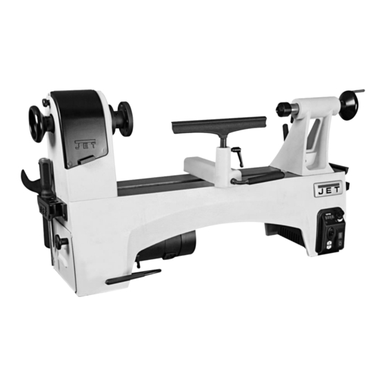
Wood lathe
Hide thumbs
Also See for JWL-1221VS:
- Operating instructions and parts manual (32 pages) ,
- Assembly instructions and parts list (2 pages) ,
- Operating instructions manual (44 pages)
Table of Contents
Advertisement
Quick Links
Advertisement
Table of Contents

Related Manuals for Jet JWL-1221VS


Summary of Contents for Jet JWL-1221VS
- Page 1 JWL-1221VS WOOD LATHE Original: Operating Instructions Translations: Gebrauchsanleitung Mode d´emploi Walter Meier (Tool) AG Tämperlistrasse 5 CH-8117 Fällanden Switzerland Phone +41 44 806 47 48 +41 44 806 47 58 jetinfo.eu@waltermeier.com www.jettools.com M-719200M 2013-06...
- Page 2 CE-Declaration of Conformity/ CE-Konformitätserklärung/ CE-Déclaration de Conformité Wood Lathe / Drechselmaschine / tour á bois Product / Produkt / produit: Model / Modell / modèle: JWL-1221VS Stock No. / Artikel Nr. / no. d´article: 719200M Brand / Marke / marque: Walter Meier (Tool) AG, Tämperlistrasse 5, CH-8117 Fällanden, Switzerland...
-
Page 3: Table Of Contents
Dear Customer, Many thanks for the confidence you have shown in us with the purchase of your new JET-machine. This manual has been prepared for the owner and operators of a JET JWL-1221VS wood lathe to promote safety during installation, operation and maintenance procedures. -
Page 4: General Safety Notes
In addition to the safety requirements contained in these Do not operate the electric tool near inflammable liquids or operating instructions and your country’s applicable gases. Observe the fire fighting and fire alert options, for regulations, you should observe the generally recognized example the fire extinguisher operation and place. -
Page 5: Remaining Hazards
Make all machine adjustments or maintenance with the machine unplugged from the power source. Make sure all levers and locking handles are tightened before operating the lathe. 3.3 Remaining hazards When using the machine according to regulations some remaining hazards may still exist. The rotating workpiece can cause injury. -
Page 6: Noise Emission
Tailstock spindle taper MT 2 Tailstock hole diameter 9,5mm Tailstock ram travel 57mm Centre above workbench 375mm Overall (LxWxH) 853x280x450mm Net weight 55 kg Mains 1~230V, PE, 50Hz Motor power 0,73kW (1 HP) Reference current 3,2 A 3x1,5mm² Extension cord (H07RN-F): Installation fuse protection Isolation class 4.3 Noise emission... -
Page 7: Mains Connection
Dispose of the packing in an environmentally friendly manner. Clean all rust protected surfaces with a mild solvent. Install the tool caddies: mount a tool caddy on each end of the lathe with two pan head screws (Fig 5). Fig 6 The machine will stop when you push the red OFF button (C). -
Page 8: Machine Operation
6. Machine operation 6.1 Correct operating position Always support the tool on the tool rest and guide with the palm of your hand keeping your fingers closed. (see Fig 8) Fig 10 Scraper (B, Fig 9), used for diameter scraping and to reduce ridges. -
Page 9: Bowl Turning
may require kerfs cut into the spur drive end of stock (see Fig 13). 6.5 Bowl turning Turn outside of bowl between centres. Turn a short tenon the size of the hole in the faceplate (T, Fig 16). This will allow centring the workpiece. Fig 13 Mount the centred workpiece between the spur drive centre Fig 16... -
Page 10: Sanding And Finishing
Caution: Cut with your chisel on the left side of the turning centre only. Use left hand to control cutting edge of gouge, while right hand swings tool handle around toward your body (Fig 18). Fig 19 Loosen the locking screw and open the lower pulley cover. Fig 18 Try to make one, very light continuous movement from the rim to the bottom of the bowl to ensure a clean, sweeping... -
Page 11: Installing Work Holding
Fig 22 You can now position the belt in the desired speed range. Fig 24 Remove the faceplate by loosening the two set screws (B). Push in the spindle lock and use the provided tool (C). Caution: always cut with your chisel on the left half of the workpiece only. -
Page 12: Adjusting Tool Rest
Fig 26 Fig 28 To remove, use the knockout bar to tap out the spur centre. Hold spur centre to prevent it from falling (Fig 26). Set the height to approximately 3mm above centre. Tighten indexable knob (B). The live centre is used to hold a workpiece between centres. Make sure the mating surfaces are clean. -
Page 13: Maintenance And Inspection
Note: A 3mm hex key (K) can be used to help tighten/loosen the index pin. 8.2 Inspecting motor brushes Disconnect the machine from the power source (unplug) ! A heavily worn or damaged brush may eventually cause damage to the motor. Periodically inspect the two carbon brushes, located at each side of the motor. -
Page 14: Trouble Shooting
Thread it on to the spindle until its snug, then back off slightly Check connectors of sensor cord to switch box. and tighten the grub screws. Readjust sensor closer to sensor collar. Mont the sensor in proximity of 0,5~1mm to the sensing Replace sensor collar (JWL-1221VS-110). collar. Replace sensor set (JWL-1221VS-112). -
Page 15: Environmental Protection
“E7” shown on digital readout *Motor sensor not working- Check connectors of sensor cord to switch box. Readjust sensor closer to sensor collar. Replace sensor collar (JWL-1221VS-254). Replace sensor set (JWL-1221VS-258). “E8” shown on digital readout *Motor cord unplugged- Check plug connection underneath the machine bed.
Need help?
Do you have a question about the JWL-1221VS and is the answer not in the manual?
Questions and answers