Advertisement
Quick Links
Advertisement

Subscribe to Our Youtube Channel
Related Manuals for Newport FPM-8220


Summary of Contents for Newport FPM-8220
- Page 1 User’s Guide Fiber Optic Power Meter FPM-8220 70044001 April 2018...
- Page 3 Power up Sequence ......................... 5 Firmware Upgradeability ........................6 GPIB Communication ........................6 USB Communication ........................6 Connecting a Measurement Head ....................6 Tilt Foot Adjustment ......................... 6 Rack Mounting ..........................6 April 2018 FPM-8220...
- Page 4 Display ............................10 Error Codes ............................ 11 The FPM-8220 Fiber Optic Measurement Heads ............12 Protecting the FMH-8705 Fiber Optic Measurement Head ............12 Protecting the FMH-8715 and FMH-87107 Fiber Optic Measurement Heads ......13 ...
- Page 5 Remote Command Reference Summary ............... 39 Command Reference ....................42 Chapter 5: Troubleshooting ..............67 Troubleshooting Guide ....................68 Optical Measurement Problems ....................71 Error Messages ......................72 Error Code Tables .......................... 72 April 2018 FPM-8220...
- Page 6 This page was intentially left blank. April 2018 FPM-8220...
- Page 7 Prolonged storage under adverse conditions Failure to perform intended measurements or functions If necessary, return the instrument to ILX Lightwave, or authorized local ILX Lightwave distributor, for service or repair to ensure that safety features are maintained. April 2018 FPM-8220...
- Page 8 Maximum Relative Humidity: <80% RH, non-condensing Operating temperature range of 0 °C to 40 °C Storage and transportation temperature of –40 °C to 70 °C Maximum altitude: 3000 m (9843 ft.) This equipment is suitable for continuous operation. April 2018 FPM-8220...
- Page 9 ILX Lightwave Corporation shall not be liable for any incidental, special, or consequential damages. If a problem occurs, please contact ILX Lightwave Corporation with the instrument's serial number, and thoroughly describe the nature of the problem. April 2018 FPM-8220...
- Page 10 If the instrument is damaged, file a claim with the carrier. The factory will supply you with a quotation for estimated costs of repair. You must negotiate and settle with the carrier for the amount of damage. April 2018 viii FPM-8220...
- Page 11 ILX Lightwave; ILX recommends you insure the shipment. If the original shipping container is not available, place your instrument in a container with at least 3 inches (7.5 cm) of compressible packaging material on all sides. We look forward to serving you even better in the future! April 2018 FPM-8220...
- Page 12 This page was intentionally left blank. April 2018 FPM-8220...
- Page 13 Chapter 1: Introduction and Specifications This chapter is an introduction to the FPM-8220 Fiber Optic Power Meter and the FMH-8705, FMH-8715 and FMH-87107 Fiber Optic Measurement Heads. This chapter also includes: Safety considerations and instructions Product Overview ...
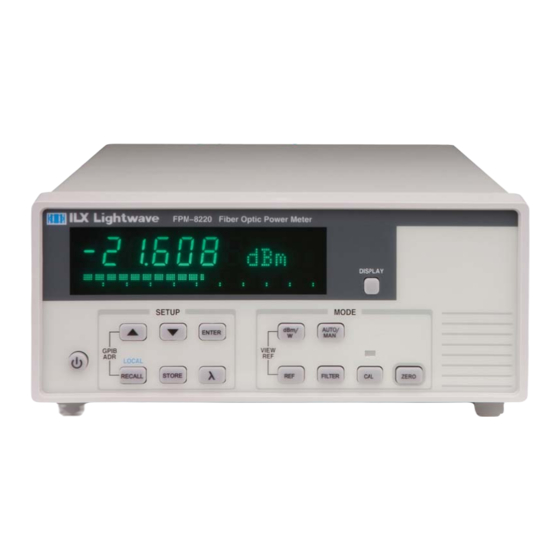
- Page 14 The fiber optic measurement head includes a two meter cable for convenient positioning near the device under test A heavy, robust design for production test workstations Customer upgradeable firmware via USB Figure 1.1 – FPM-8220 Front Panel Figure 1.2 – FPM-8220 Rear Panel April 2018 FPM-8220...
- Page 15 Options and Accessories Options and accessories available for the FPM-8220 Fiber Optic Power Meter and the FMH-8700 series Fiber Optic Measurement Heads include the following: Description Model / Part Number FC Adapter CA -100 SC Adapter CA -150 LC Adapter...
- Page 16 Specifications April 2018 FPM-8220...
- Page 17 Chapter 2: General Operation This chapter describes how to set up and operate the FPM-8220 Fiber Optic Power Meter using the front panel controls. Installation Introduction to the FPM-8220 front panel FMH-8700 series fiber optic measurement head familiarization ...
- Page 18 Tilt Foot Adjustment The FPM-8220 has front legs that extend to make it easier to view the displays. To use them, rotate the legs downward until they lock into position.
- Page 19 Front Panel Operation This section describes the fundamentals of front panel operation for the FPM-8220 Fiber Optic Power Meter. Both of the labeled areas on the front panel, SETUP and MODE, and the display are described below. Figure 2.1 – Front Panel Display...
- Page 20 The wavelength adjustment range is dependent upon the FMH-8700 series Fiber Optic Measurement Head connected to the FPM-8220. Local When the instrument is in remote operation mode, pressing the RECALL pushbutton will put the instrument back to local (front panel) control mode.
- Page 21 8220 will zero the current gain range or all gain ranges accordingly Display Pressing DISPLAY cycles the bottom dot matrix display from the instrument’s setting information to the brightness of the display to a bar graph. April 2018 FPM-8220...
- Page 22 Bar Graph - The bar graph display shows relative input level as a percentage of full scale for each gain range. In fast and medium filter speeds, the bar graph will update at 50ms. In slow filter speed, the bar graph will update every 200ms. April 2018 FPM-8220...
- Page 23 Figure 2.5 – Bar Graph Display Error Codes The FPM-8220 indicates front panel operation errors on the measurement display with an error code. A complete list of error codes is listed in Chapter 5. April 2018 FPM-8220...
- Page 24 The FPM-8220 Fiber Optic Measurement Heads The FPM-8220 is compatible with three fiber optic measurement heads: FMH-8705 InGaAs, Fiber Optic Measurement Head, Detector Only (+1.5 to -85 dBm) FMH-8715 InGaAs, Fiber Optic Measurement Head, Integrating Sphere (+20 to -70 dBm)
- Page 25 Note: Always clean the tip of the connector ferrule before a measurement, using the proper tools and a good technique. The core of a single-mode telecom-grade fiber is only about 9μm in diameter; the smallest contaminant can cause significant errors. To remove an adaptor, grasp its outer ring and pull it out. April 2018 FPM-8220...
- Page 26 Check that the adaptor ring is flush to the face of the detector head all around. Rotating the ring helps to ensure that it is seated properly. Figure 2.8 - CA-120 Bare Fiber Adapter Ring April 2018 FPM-8220...
- Page 27 3. Lay the fiber in the holder with the stripped and cleaved fiber protruding from the nose (detector-side) of the holder. 4. Gently pull the fiber until the buffer is aligned with the marks on the holder. Make sure the buffer does not extend beyond the marks, toward the nose-end of the holder. April 2018 FPM-8220...
- Page 28 5. The fiber must extend between1.0 mm and 5.0 mm from the holder to ensure accurate measurements from the FPM-8220. 6. Release the feet and close the holder. The holder is held shut by a spring and several magnets. Grasping the holder by the body, insert the fiber holder into the bare-fiber adaptor ring making sure that the fiber endface does not touch anything.
- Page 29 Photodetector Responsivity The FPM-8220 Fiber Optic Meter is a stable, low noise current meter that is compatible with three fiber optic measurement heads: the FMH-8705, the FMH-8715 and the FMH-87107. The FMH-8705 is a detector only, fiber optic measurement head design to measure very low power.
- Page 30 A BNC output connector is provided on the rear panel to give you direct access to the amplified photodetector signal. Keep the FPM-8220 in manual range mode when you use the analog output. This is a very low-noise, stable output that is normalized to 10V to represent percentage of full scale.
- Page 31 100nA 10nA Determining Range The FPM-8220 will display the gain range by pressing AUTO/MAN or the UP ARROW or the DOWN ARROW. Relating Optical Power to Analog Voltage The most direct way to relate optical power to analog voltage is to read the power from the front panel or by remote interface while noting the voltage.
- Page 32 2. The factory calibration certificate includes a table of detector response at every 10 nm. The accuracy of power measurement via the analog output of the FPM-8220 is not a factory specification; however, the user will find it to be stable, reliable, and useful. The following relationship will allow the user to convert analog voltage output into power output.
- Page 33 Remote operations are discussed in the next chapter. Warm-up and Environmental Considerations To achieve the rated accuracy, allow the FPM-8220 to warm up for at least one hour before use. Operate the meter within the environmental limits specified in Chapter 1. The best accuracy is achieved near the calibration temperatures.
- Page 34 April 2018 FPM-8220...
- Page 35 Chapter 3: Remote Operation This chapter is an overview of the remote operation of the FPM-8220 Fiber Optic Power Meter. Applying power Connecting to the instrument Front panel operation GPIB (General Purpose Interface Bus) is the common name for ANSI/IEEE Standard 488, an industry standard for interconnecting test instruments in a system.
- Page 36 Basic GPIB Concepts The basic GPIB concepts are not necessary to successfully operate the FPM-8220, but are a useful perspective in understanding GPIB communication. Data and Interface Messages GPIB devices communicate with each other by sending data and interface messages. Data contains device-specific information such as programming instructions, measurement results, and instrument status.
- Page 37 Eight data I/O (DIO) lines carry both data (including device dependent commands) and interface messages. The ATN interface management line determines whether these lines contain data or interface messages. Figure 3.2 - GPIB April 2018 FPM-8220...
- Page 38 (front panel) control mode. SRQ (service request) can be set by any device in the system to request service from the controller. EOI (end or identify) is used by talkers to identify the end of a message. April 2018 FPM-8220...
- Page 39 When the USB device is enumerated and gets an address from the host, it presents the host with information about itself in the form of a series of descriptors. The device descriptor tells the host the vendor and the product ID. The configuration descriptors offer a power consumption April 2018 FPM-8220...
- Page 40 Multiple commands/queries separated by semicolons and issued as one command string are only acknowledged with a “Ready” response if the entire command string contains no queries. (See the Command Separators section later in this chapter for additional details.) April 2018 FPM-8220...
- Page 41 (Chapter 4). Upper/lower case does not matter to the FPM-8220. It is just used in this manual to identify optional letters. The optional letters must be in the correct sequence. Some examples of what works, and what does not: Table 3.1 –...
- Page 42 Many computers terminate with <CR><NL><END> (Carriage Return – New Line – EOI). A carriage return (<CR>) is read as white space. The FPM-8220 terminates its responses with <NL><END>, unless the TERM command is used to change it. If problems are encountered with remote communication, the terminator string can be the cause.
- Page 43 For further clarity in programming, the Boolean values of one (1) and zero (0) may be used or their names as indicated in Table 3.5. Table 3.5 – Substitute Parameter Values Substitute Name Value April 2018 FPM-8220...
- Page 44 Command Tree Structure The FPM-8220 Fiber Optic Power Meter device-dependent commands are structured in a tree format as shown in Figure 3.3. Each of the legal paths is shown, followed by its list of path options, followed by the commands themselves. It is recommended that the first-time user begin learning the commands by using the full path notation.
- Page 45 Table 3.6 – Invalid Syntax Command Strings COMMAND COMMENT Missing colon; SYSTEM ERROR? Missing semicolon RANGE:AUTO 1 *IDN? Space not allowed before question mark. ADDRESS:GPIB ? Space missing between WAVE command and the parameter WAVE1234;*IDN? value 1234. April 2018 FPM-8220...
- Page 46 Numeric data is required with *PSC (1 = on, 0 = off), *RCL (0 – 10, see front panel Recall function), *SAV (1 – 10, see front panel Store function), and *ESE (0 – 255, see Figure 3.5 – GPIB connector diagram). All the IEEE 488.2 Common Commands supported by the FPM-8220 are listed in Table 3.7. April 2018 FPM-8220...
- Page 47 Table 3.7 – IEEE 488.2 Common Commands Supported by FPM-8220 *CAL? *CLS *ESE *ESE? *ESR? *IDN *OPC *OPC? *PSC *PSC? *RCL *RST *SAV *SRE *SRE? *STB? *TST? *WAI See Chapter 4 – Command Reference for descriptions of all commands, including common commands, supported by the FPM-8220.
- Page 48 Event and Condition Registers for power meter operations. The Event Registers are used to report events which occur during the operation of the FPM-8220 Fiber Optic Power Meter. Events differ from conditions in that events signal an occurrence one time, and are not reset until the Event Register is queried or the FPM-8220 is powered off.
- Page 49 This allows the use of the operation complete features of the FPM-8220, without the need for program looping or polling which can tie up the GPIB bus. Operation Complete on the FPM-8220 is defined as: ...
- Page 50 Query responses are evaluated at the time the query request is parsed, and not at the time the response message is sent. In most cases, this does not create a problem since the time between parsing a query and sending its response is small. April 2018 FPM-8220...
- Page 51 Chapter 4: Command Reference This chapter is a guide to all of the device-dependent commands for the FPM-8220 Fiber Optic Power Meter. This chapter is divided into two parts. Overview of the remote commands List of remote commands in alphabetical order within the categories of IEEE 488.2 common commands, device specific commands, and extra commands.
- Page 52 TIME? NONE Requests time since the last TIMER? query TIMER? NONE Set wavelength for calibrating detector response WAVE Request wavelength for detector response WAVE? NONE Optional. Zero specific range. ZERO Request status of zero operation NONE ZERO? April 2018 FPM-8220...
- Page 53 Request the reference level value SENSe:POWer:REFerence? NONE Selects Logarithmic (dBm) unit or linear units SENSe:POWer:UNIT (Watts) to be used in reporting measurements Requests FPM-8220's measurement mode. SENSe:POWer:UNIT? NONE Set wavelength for calibrating detector response SENSe:POWer:WAVelength Request wavelength for detector response...
- Page 54 Adjusts the internal analog to digital (A/D) converter to reference points, then reports results. Response Zero = OK Non-zero = calibration error Notes The A/D chip in the FPM-8220 performs automatic calibration. Thus, this query always return 0. Example *CAL? *CLS Common...
- Page 55 Response is the sum of the enabled bits and must be a value between 0 and 255. Allows for the determination of which type of error has occurred. Examples “*ESR?” –response: 32, meaning a command error has occurred. April 2018 FPM-8220...
- Page 56 Places an ASCII character 1 into the instrument’s Output Queue when all pending operations have been finished. Parameters None. Notes See the IEEE 488.2 specification for additional information. Examples *OPC? –response: “1” when all overlapped commands are complete. April 2018 FPM-8220...
- Page 57 The *SAV function is used to save configurations for convenient recall. The current setup is automatically stored and recalled at the next power-on, unless *PSC is used to enable the power-on status clear flag. Examples “*RCL 0” –response: instrument is reconfigured to factory-default settings. April 2018 FPM-8220...
- Page 58 Refer to Figure 3.5 in Chapter 3 for a complete description of the Status Byte and Service Request Enable Register. Examples “*SRE 136” –action: enables the service request enable register when a device condition summary or an error is available. April 2018 FPM-8220...
- Page 59 Care should be taken to set the GPIB time-out appropriately for use with the *WAI command. After this command (or the Delay) command is sent, the instrument may receive up to 20 more commands before the wait period is over. Examples “*WAI” –action: wait until OPC status is true. April 2018 FPM-8220...
- Page 60 CAL:USER <nrf value> Device Dependent Front Panel Action Sets a gain factor to be applied to all FPM-8220 measurements. Parameters 0.500 to 2.500 Indicators Front panel USER CAL indicator is ON when the gain factor is any other value than 1.000.
- Page 61 Small delay values may have no effect, because of time required for command processing. The actual minimum delay depends on the situation, for example whether a measurement is being done in background. This delay command can be useful for creating delays based on the FPM-8220 clock rather than using the controller's clock. Examples DELAY 2000 - Delay further processing 2 seconds.
- Page 62 COND?. See Chapter 3 for more information about register structure. Examples ENAB:COND? - Response 4 means that over range will be reported in status byte bit 3. Enable:COND? - Response #H4 is the same as 4, except using hexadecimal numbering. See RADix. April 2018 FPM-8220...
- Page 63 EVEnt?. See Chapter 3 for more information about register structure. Examples ENAB:EVE? - Response 2048 means that measurement ready will be reported in status byte bit 2. Enable:event? - Response #H800 is the same as 2048, except using hexadecimal numbering. See RADix. April 2018 FPM-8220...
- Page 64 FILTER SLOW - Updates the display every 5 seconds with the average of 100 measurements. Filter med - Updates the display every 0.5 seconds with the average of 10 measurements. FILT Fast - Turns off measurement averaging. Updates the display every 50 milliseconds. April 2018 FPM-8220...
- Page 65 Device Dependent Front Panel Action Stores an ASCII string into FPM-8220 non-volatile memory. Notes String is 1 to 16 non-zero ASCII characters. Strings longer than 16 characters are terminated to the first 16. Strings shorter than 16 characters are filled with spaces to 16.
- Page 66 MODE? Common Device Dependent Front Panel Action Requests FPM-8220's measurement mode. Response One of the following ASCII character strings: Notes This information is available on front panel indicators. See Chapter 2. The response to MODE? is the units of value that will be used for responses to a POW? request.
- Page 67 This current is proportional to optical power, but it also varies with wavelength. For more information about gain ranges, see Gain Ranges on page 19. There are eight ranges in the FPM-8220 meter. Each range increases gain by 10x over the previous range. The maximum photodetector current for each range is as follows...
- Page 68 Integer number: 0 through 7 Notes See the discussion of RANge above for information about gain ranges. Response is valid whether the FPM-8220 is in MANUAL or AUTO range mode. Range information is not displayed on the FPM-8220 front panel. Example...
- Page 69 The information should correspond with that on your latest ILX Lightwave calibration certificate for this meter. If not, contact ILX Lightwave Customer Service to resolve the discrepancy. This information can be useful for understanding the characteristics of your FPM-8220 meter. Notice for example that detector current is much less at shorter wavelengths.
- Page 70 All settings other than TERM 4 are out of compliance with IEEE-488.2 specifications. They are provided for flexible compatibility with various GPIB drivers. See TERM (above) for more information. Examples Term? - Response 4 means the message terminator is the FPM-8220 default: <NL><^END> TIME? Common Device Dependent...
- Page 71 The FPM-8220 keeps the last zero setting, even when you turn power OFF. So if you zero the meter to your test setup, be sure to zero the meter again when you are finished. It may be more convenient to do this with the front panel ZERO button.
- Page 72 ZERO? Common Device Dependent Front Panel Action Requests status of the FPM-8220 zero operation. Response 0 = zero operation is not in progress. 1 = zero operation is in progress. Examples ZERO? - Response 1 means the zero operation is in progress.
- Page 73 In dB or dBm mode, reports the same number as on the display. In W mode, reports in scientific notation. Monitor the Device Event Status Register for over-range or under-range conditions when using this query. Examples Mode?;READ:POWer? - Response of DBM,-13.584 means the last measured power was-13.584 dBm. April 2018 FPM-8220...
- Page 74 The FPM-8220 keeps the last zero setting, even when you turn power OFF. So if you zero the meter to your test setup, be sure to zero the meter again when you are finished. It may be more convenient to do this with the front panel ZERO button.
- Page 75 This current is proportional to optical power, but it also varies with wavelength. For more information about gain ranges, see Gain Ranges on page 18. There are eight ranges in the FPM-8220 meter. Each range increases gain by 10x over the previous range. The maximum photodetector current for each range is as follows...
- Page 76 SENSe:POWer:UNIT 0 - Measurements will be reported in dBm. SENSe:POWer:UNIT? Common Device Dependent Front Panel Action Requests FPM-8220's measurement mode. Response 0 = logarithmic unit 1 = linear unit Notes This information is available on front panel indicators. See Chapter 2.
- Page 77 Notes The FPM-8220's InGaAs detector produces current in proportion to light input. The amount of current varies also with wavelength. For this reason, it is important to give the FPM-8220 correct wavelength information. Calibration points are basically every 10 nm. When you give the FPM-8220 a wavelength between two calibration points, the resulting calibration factor is a linear interpolation between the two points.
- Page 78 April 2018 FPM-8220...
- Page 79 Customer Service. See page viii for contact information. ILX Lightwave Corporation provides in-house and on-site calibration services for ILX instruments. Most ILX instruments, including the FPM-8220 require yearly calibration to ensure performance to published specifications. ILX factory calibrations employ NIST traceable measurement instrumentation, and our calibration engineers and technicians use automated test equipment to accurately and efficiently capture and record calibration data.
- Page 80 5.0% of full scale for the current gain range. The instrument reads “Internal E-532 is the internal communication error indicating, the Communication Error” FPM-8220 platform, is not functioning correctly. The instrument must be returned to ILX Lightwave if this error occurs. April 2018 FPM-8220...
- Page 81 Check that a GPIB or USB A/B cable, from the system and the RMT indicator is off controller, is connected to the FPM-8220. If you are using GPIB, the cable should be less than 3 meters (10 feet) long. Press RECALL and the UP ARROW at the same time to display the GPIB address for three seconds.
- Page 82 Is the FPM-8220 ANSI/IEEE 488.2 The FPM-8220 is IEEE 488.2 compliant. compatible? Problems using the Device Clear The DCAS interrupt is not connected to the necessary microprocessor for clearing bus-hung conditions via Device Clear. The firmware does not terminate or complete all commands upon a Device Clear because of firmware/hardware timing issues and GPIB/USB architecture.
- Page 83 Remotely, when a gain range specified is outside operational parameters, the instrument adds the error message “Data out of range” to the error queue. The closest valid gain range to the specified gain range will be selected. April 2018 FPM-8220...
- Page 84 Error Messages Error messages may appear on the FPM-8220 display when error conditions occur in the instrument. In remote operation, use ERR? to read the current error list or SYST:ERR? to read the latest error. The ERR? command returns a string containing up to 10 of the error messages that are currently in the error message queue.
Need help?
Do you have a question about the FPM-8220 and is the answer not in the manual?
Questions and answers