Advertisement
Quick Links
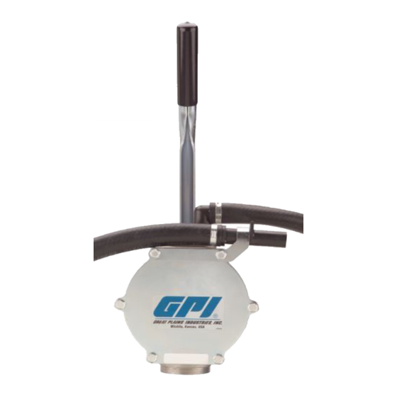
HP-90
Petroleum Hand Pump
Owner's Manual
INSTALLATION
Know and follow applicable national, state and local
safety codes pertaining to installing and operating equip-
ment for use with petroleum fluids
Make sure the tank is vented to prevent the buildup of
pressure and possible fuel leakage through the nozzle.
Use the following procedures to install the HP-90 Hand
Pump on a tank with a 2-inch NPT bung.
Install Suction Pipe
1. Place PVC pipe into flared end of PVC pipe assem-
bly. Use PVC cement if desired. The end of the pipe
should be 2-3 inches above the bottom of the tank,
when installed correctly. Cut pipe to fit tank.
2. Remove the two protective plugs from the inlet and
outlet ports.
3. Wrap the threaded end of the suction pipe with 3 to
4 turns of thread tape.
09/11
4. Install the suction pipe into the pump inlet and tighten
with a wrench.
Install Pump on Tank
1. Lubricate the male threads on the pump inlet with
thread tape or a thread-sealing compound approved
for use with petroleum fuels.
2. Thread the pump onto the tank and turn pump to
tighten securely.
Install Handle
1. Slide the grip onto the pump handle.
2. Install one end of the link in the pump housing, the
other end in the bottom hole in the pump handle.
Connect the pump handle to the shaft with the clevis
pin and secure with the cotter pin.
Lubricate all Pin Joints with grease
to extend the life of your hand pump.
5252 East 36th Street North
Wichita, KS USA 67220-3205
TEL: 316-686-7361
FAX: 316-686-6746
Rev. - 921925-06
Advertisement

Subscribe to Our Youtube Channel
Related Manuals for GPI HP-90


Summary of Contents for GPI HP-90
- Page 1 Use the following procedures to install the HP-90 Hand Connect the pump handle to the shaft with the clevis Pump on a tank with a 2-inch NPT bung.
- Page 2 GPI can also inform you of any 2. Suction pipe leak. Repair or replace as needed. special requirements you will need to follow for shipping.
- Page 3 ILLUSTRATED PARTS DRAWING Item Part No. Description req’d. 906001-43 Handle Grip ........1 904006-32 Clevis Pin, 3/8 in......1 904002-58 Hitch Clip Pin ........1 904001-55 Retaining Ring ........ 4 131034-1 Fuel Hose Assembly, 3/4 in.... 1 131033-1 Nozzle Bracket .......
- Page 4 St. North Wichita, KS, USA 67220-3205 GPI will step you through a product troubleshooting process to determine appropriate corrective actions. GREAT PLAINS INDUSTRIES, INC., EXCLUDES LIABILITY UNDER THIS WARRANTY FOR DIRECT, INDIRECT, INCIDENTAL AND CONSEQUENTIAL DAMAGES INCURRED IN THE USE OR LOSS OF USE OF THE PRODUCT WARRANTED HEREUNDER.
Need help?
Do you have a question about the HP-90 and is the answer not in the manual?
Questions and answers