Advertisement
Quick Links
Advertisement

Related Manuals for Axis 282


Summary of Contents for Axis 282
- Page 1 AXIS 282/282A Bare Board Video Server Installation Guide...
-
Page 3: Installation Guide
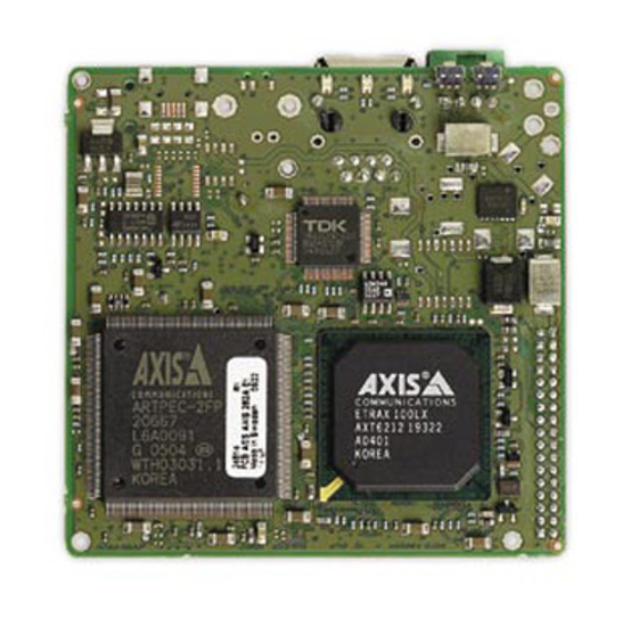
For a complete description, get the AXIS 282/282A Bare Board Video Server User’s Manual online from Axis Web site, www.axis.com The AXIS 282/282A is a small form factor video server board designed to be built into domes, fixed view cameras, PTZs, analog devices, etc., and is fully featured for security surveillance and remote monitoring needs. - Page 4 Page 2 AXIS 282/282A Top Network connector Terminal I/O connector Mounting hole Not included: •4 M2 screws - needed for mounting AXIS 282/282A •34 pin IDC female connector (2mm) AXIS 282/282A Mounting holes 34-pin header Installation Guide Mounting hole...
-
Page 5: The Terminal I/O Connector
Pins 3 and 4 in the Terminal I/O Connector are the same Alarm In and Alarm Out as pins 8 and 9 in the 34-Pin Header. If the AXIS 282/282A has been configured to have power going in through the 34 I/O pins, power can be configured to go out through pin 1 of the Terminal I/O Connector. -
Page 6: The 34-Pin Header
Page 4 The 34-Pin Header The AXIS 282/282A has a 34-Pin Header to be used with a 2mm IDC connector. Connections include: •Serial port, configurable as RS-232 or RS-485, which is typically used for con- necting Pan/Tilt/Zoom devices. •Video in and out connections •Audio in and out connections... - Page 7 AXIS 282/282A Installation Guide Page 5 Schematic Diagram - 34 I/O Pins Note: Pins 8 and 9 in the 34-Pin Connector are the same Alarm In and Alarm Out as pins 3 and 4 in the Terminal I/O Connector.
- Page 8 Control button - Used to restore the factory default settings, as described in AXIS 282/282A User’s Manual. Flash button - The AXIS 282/282A has a flash button. Used only for firmware programming in the factory and not when upgrading the...
- Page 9 Page 7 Integration of the AXIS 282/282A Mechanical integration may be done through the 4 mounting holes on the AXIS 282/282A, shown in the figure below. Electrical integration of the AXIS 282/282A is done through the connectors described here. Mounting holes...
-
Page 10: Technical Specifications
HTTP or FTP, firmware available at www.axis.com maintenance Approvals • AXIS 282/AXIS 282A is delivered as a component for the sole purpose of being integrated into a product or system. The foregoing implies an obligation on behalf of the integrator to obtain any approvals from... - Page 12 AXIS 282/282A Installation Guide v1.0 August 2006 Copyright © Axis Communications AB, 2006 Part No. 27335...
Need help?
Do you have a question about the 282 and is the answer not in the manual?
Questions and answers