Table of Contents
Advertisement
Quick Links
Advertisement
Table of Contents
Troubleshooting

Related Manuals for Vollrath Stoelting CF101


Summary of Contents for Vollrath Stoelting CF101
- Page 1 A VOLLRATH® DIVISION Model CF101 OPERATORS MANUAL Manual No. 513624 Rev.4...
- Page 3 Stoelting White Glove Service. For warranty information, visit stoeltingfoodservice.com Stoelting Foodservice Equipment White Glove Service Network 502 Highway 67 Phone: 888.319.9549 Kiel, WI 53042-1600 A VOLLRATH® DIVISION U.S.A. © 2021 Stoelting stoeltingfoodservice.com...
- Page 4 A Few Words About Safety Safety Information Safety Alert Symbol: Read and understand the entire manual before This symbol Indicates danger, warning or caution. operating or maintaining Stoelting equipment. Attention is required in order to avoid serious personal injury. The message that follows the symbol contains This manual provides the operator with information important information about safety.
-
Page 5: Table Of Contents
Table of Contents Section Description Page Section 1 - Description and Specifications Description........................1 Specifications ........................2 Section 2 - Description and Specifications Safety Precautions ......................3 Shipment and Transit ....................3 Machine Installation.......................3 Section 3 - Initial Set-Up And Operation Operator’s Safety Precautions ..................5 Operating Controls And Indicators ................5 Sanitizing ..........................7 Freeze Down And Operation ..................7... -
Page 7: Section 1 - Description And Specifications
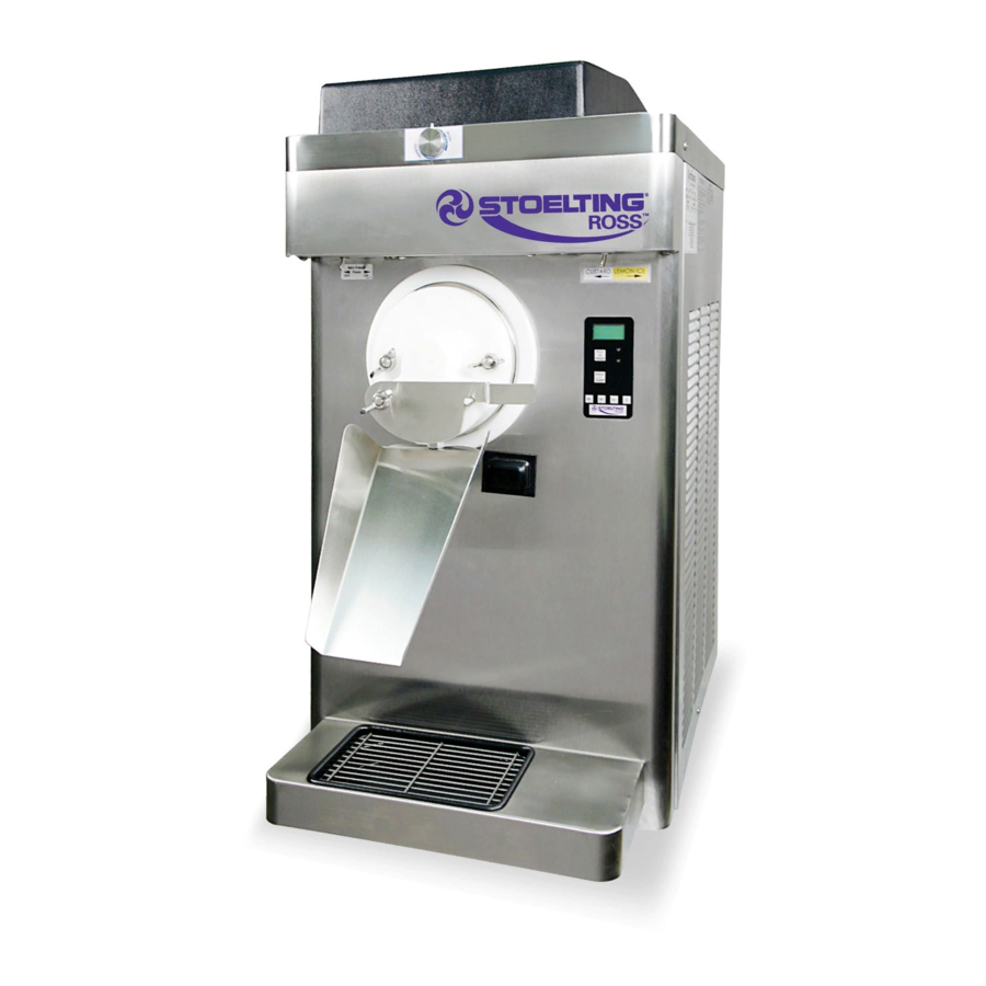
Section 1 - Description and Specifications DESCRIPTION The CF101 is a countertop continuous flow custard machine. It is equipped with fully automatic controls to provide a uniform product and features Quick-Freeze technology. This manual is designed to assist qualified service per- sonnel and operators in the installation, operation and maintenance of the CF101 frozen custard machine. -
Page 8: Specifications
SPECIFICATIONS CF101 Dimensions Machine with crate width 19-1/2’’ (49,5 cm) 38-3/4’’ (98,4 cm) height 37-3/4’’ (95,9 cm) 28-3/4’’ (73,0 cm) depth 28’’ (71,1 cm) 43’’ (109,2 cm) Weight 310 lbs (140,6 kg) 410 lbs (185,9 kg) Electrical 1 Phase, 208-240 VAC, 60Hz running amps connection type NEMA6-20P power cord provided... -
Page 9: Section 2 - Description And Specifications
Section 2 - Description and Specifications SAFETY PRECAUTIONS Uncrate the machine. Accurate leveling is necessary for correct drainage Do not attempt to operate the machine until the safety of machine barrel and to ensure correct overrun. precautions and operating instructions in this manual are Place a bubble level on top of the machine at each read completely and are thoroughly understood. - Page 10 Operators Manual #513624 CF101 Model Machines...
-
Page 11: Section 3 - Initial Set-Up And Operation
Section 3 - Initial Set-Up And Operation OPERATOR’S SAFETY PRECAUTIONS 3.2 OPERATING CONTROLS AND INDICATORS SAFE OPERATION IS NO ACCIDENT; observe these rules: Before operating the machine, it is required that the op- erator know the function of each operating control. Refer Know the machine. - Page 12 Product Selector Switch Push to Freeze The product selector switch changes the Green LED refrigeration profile to allow two different products to be made. Before the machine is in ready mode, Amber LED this switch can be moved to the desired profile. Purge/Clean PUSH TO FREEZE Button Button...
-
Page 13: Sanitizing
3.3 SANITIZING Place a bucket under the slide. Pour the sanitizer into the hopper. Sanitizing must be done after the machine is cleaned and just before the hopper is filled with mix. Sanitizing the night NOTE before is not effective. However, you should always clean A small amount of sanitizer may drain into the the machine and parts after each use. -
Page 14: Hold Cycle
Turn the flow control knob to the second band Adjust the flow control knob until the product for approximately 3 seconds then turn the knob flow fills the faceplate outlet and is at the desired to “OFF”. texture (Fig. 3-8). The flow control knob setting is different for each type of product. -
Page 15: Production From Hold
3.6 PRODUCTION FROM HOLD Turn the flow control knob to the first band for approximately 3 seconds then turn the knob to Press the PUSH TO FREEZE button. “OFF”. Open the front gate. Collect any liquid mix that comes out of the freezing cylinder in a sanitized container and treat it as rerun. -
Page 16: Removing Mix From Machine
HOLD CYCLE - ITALIAN ICE Replace the front gate with the splash guard and turn the flow control knob to the second band. Turn flow control knob to the OFF position. Press the PURGE/CLEAN button twice. The display Press the PURGE/CLEAN button. The display reads reads CLEAN. -
Page 17: Cleaning The Machine Parts
To disassemble the machine, refer to the following steps: 3.11 CLEANING THE MACHINE PARTS Disassembled machine parts require complete cleaning, sanitizing and air drying before assembling. Local and CAUTION state health codes dictate the procedure required. Some Hazardous Moving Parts state health codes require a four sink process (pre-wash, wash, rinse, sanitize, air dry), while others require a three Revolving auger shaft can grab and cause injury. -
Page 18: Routine Cleaning
NOTE 3.13 ROUTINE CLEANING The United States Department of Agriculture and To remove spilled or dried mix from the machine exterior, the Food and Drug Administration require that lubri- wash in the direction of the finish grain with warm soapy cants used on food processing equipment be certi- water and wipe dry. -
Page 19: Extended Storage
3.15 EXTENDED STORAGE For water-cooled machines that are left in unheated buildings, or buildings subject to freezing, the water Refer to the following steps for winterizing the machine or must be shut off and disconnected. Disconnect for storing the machine over any long period. the water inlet fitting. - Page 20 Operators Manual #513624 CF101 Model Machines...
-
Page 21: Section 4 - Troubleshooting
Section 4 - Troubleshooting ERROR CODES Error Code 3 - Run Time When the machine experiences a problem, one of the The Run Time Error (E3) occurs when the following error codes is displayed on the control panel. compressor runs continuously for an extended Each error code directs you to the system location of the period. - Page 22 Error Code 5 - Freezing Cylinder Sensor Error Code 9 - High Pressure Cutout The Freezing Cylinder Sensor Error (E5) indicates High Pressure Cutout Errors (E9) are usually a failure of the barrel sensor or if the sensor is out caused by a dirty or inefficient condenser.
-
Page 23: Troubleshooting Tables
4.3 TROUBLESHOOTING TABLES PROBLEM POSSIBLE CAUSE REMEDY Flow is not high enough. Increase the flow. Machine needs to run for at least a minute before seeing a change in the Custard is running product. too cold or auger 2 Hopper is low or out of mix. 2 Add Mix blades chatter 3 Flow valve is plugged. - Page 24 Operators Manual #513624 CF101 Model Machines...
-
Page 25: Section 5 - Replacement Parts
Section 5 - Replacement Parts DECALS AND LUBRICATION Part Description Quantity C-2000-57 Wrench - Auger Shaft O-Ring Pick 208135 Brush - 4” x 8” x 16” (Barrel) 208401 Brush - 1” x 3” x 10” 232091 Cap - Protective (Gray) - #490716 Leg 236048 Card - Cleaning Instruction 324105... -
Page 26: Auger Shaft And Faceplate Parts
5.2 AUGER SHAFT AND FACEPLATE PARTS M-MC101-09 M-MC101-09 SL-0010 SL-0010 M-MC101-06 M-MC101-06 336562 336562 149003 149003 2183948 2183948 2187602 2187602 625140 625140 NT-0010 NT-0010 C-4000-20 C-4000-20 Part Description Quantity C-2000-40 Wearguard - Auger Shaft (Ser. #0 - #27431) C-4000-19 Slide - Long (Chute) (14”) C-4000-20 Slide - Short (Chute) (10”) M-MC101-06... -
Page 27: Hopper Parts
5.3 HOPPER PARTS 754038 754038 314484 314484 417010 417010 630049-SV 630049-SV 744287 744287 744276 744276 Part Description Quantity 314484 Cover - Hopper 417010 Insert - Drip Tray 630049-SV Rod - Flow Control 744276 Tray - Drain (18 3/8” Long) 744287 Tray - Drip (Black) 754038 Tube - Flow Control (Hopper) - Page 28 Operators Manual #513624 CF101 Model Machines...
Need help?
Do you have a question about the Stoelting CF101 and is the answer not in the manual?
Questions and answers