Advertisement
Available languages
Available languages
Quick Links
F9000 Reader/Writer
INSTALLATION GUIDE
i s e o . c o m
Non contractual document. Subject to change. Cod. KW19780 - 19/06/2019
F9000 Reader/Writer Installation guide (EN) - © 2019 Iseo Serrature S.p.a. - www.iseo.com
2. MODELS & VERSIONS
Frame Mounting Reader
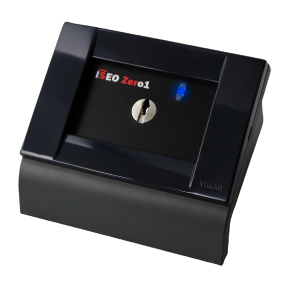
Desktop Reader
(Vimar Idea frame &
(Vimar Idea plastic box)
503 box compatible)
Wall Mounting Reader
Wall Mounting IP55 Reader
(Vimar Idea plastic box)
(Vimar Idea IP55 plastic box)
4. ELECTRICAL CONNECTIONS
6. ELECTRICAL CONNECTIONS EXAMPLE: TO ATLAS BY ETHERNET CABLE
ATLAS PLUS/STD CH1 (J5)
FTP AWG24 CAT5E
ATLAS DIN CH1 and CH2
(Max length 500mt)
A
1
R
B
2
3
(GND)
4
R = 120 ohm (1/4 W)
Ethernet cable FTP AWG24 CAT5E (and above).
Required Atlas power supply: 24Vdc.
Maximum Ethernet cable length between Atlas and F9000 Reader: 500mt.
Resistance value: 120 ohm (1/4W) on both Atlas and F9000 Reader sides.
Recommended capacitance conductor/conductor < 100pF/m.
Recommended conductors electrical resistance max 90 ohm/Km.
Connect the ethernet cable shield to the Atlas GND connector only if Atlas NOT connected to ground.
For more information about Atlas and its connectors, refer ot the Atlas Installation Guide avalable at:
app.iseo.com.
Iseo Serrature s.p.a
®
Via San Girolamo 13
25055 Pisogne (BS)
ITALY
Tel. +39 0364 8821
iseo@iseo.com
ELECTRONIC SUPPORT SERVICE
iseozero1.com
Frame Mounting GIRA
(GIRA frame & box
compatible)
Wall fixings not provided in
the kit. The installator must
choose the most suitable
fixings according to the wall
type and material.
F9000 Reader
connector (RS485)
(GND)
(10
TX/RX 485 (A)
R
TX/RX 485 (B)
R = 120 ohm - 1/4 W
Supplied with the reader
- Wiring cable not included in the kit.
- Recommended cable: Ethernet cable FTP AWG24
CAT5E (and above or equivalent data cable).
- Min/max cross-section of the wires: 0.20÷1.5mm
(24÷15AWG).
- Min/max cable diameter: 3÷7mm
- Max length: up to 500mt
Ethernet cable
F9000 Reader
connector (RS485)
R
1. TECHNICAL SPECIFICATIONS
PRODUCT:
Frame, wall mounting and desktop reader/writer units for F9000 keys.
FEATURES:
- Cylinder hole for F9000 key insertion.
- RS485 communication interface.
- Power supply: by Atlas.
- Power consumption: 1W.
- Multicolor signaling LEDs (green, blue, red) and acoustic buzzer.
DIMENSIONS (LxDxH):
- Desktop version: 120 x 111 x 82 mm
- Frame Mounting 503 version: 120 x 82 x 55 mm
- Frame mounting GIRA version: 80 x 80 x 50 mm
- Wall Munting Vimar version: 120 x 88 x 55 mm
- Wall Munting Vimar IP55 version: 100 x 83 x 65 mm
ENVINRONMENTAL CHARACTERISTICS:
- Operating temperature: -10°C ÷ +50°C (internal version).
- Operating temperature: -25°C ÷ +50°C (external IP55 version).
- Storage temperature: -25°C ÷ +75°C.
3. WARNINGS
Read this manual prior to use the device in order to ensure a safe and proper use.
Preserve this manual as future reference.
The installation of the device requires the intervention of qualified staff, adequately trained by ISEO.
The instructions should be carefully followed during the use of the product. These instructions should be
passed on by the installer to the user.
No modifications of any kind are permitted, except for those described in these instructions.
The product must be destined only for the use for which it is expressly designed and therefore as a reader and
writer unit for civil and industrial locations. Any other use is considered improper and dangerous.
5. ELECTRICAL CONNECTIONS TO ATLAS
ATLAS DIN
÷
24 Vdc)
2
6.1 ELECTRICAL CONNECTIONS EXAMPLE: TO ATLAS CH2 BY ETHERNET CABLE
ATLAS PLUS/STD CH2 (J11)
and CH1 (J5)
CH1
1
1
B
2
2
A
(GND)
(GND)
3
3
4
4
CH2
1
2
A
3
R
B
4
5
6
See warnings at box 6.
https://www.iseo.com/it/it/download
ATLAS STANDARD (STD)
ATLAS PLUS
1
2
CH2
3
(GND)
4
1
2
CH1
(GND)
3
4
Ethernet cable
FTP AWG24 CAT5E
(Max length 500mt)
R = 120 ohm (1/4 W)
1
2
CH1
(GND)
3
4
1
2
3
CH2
4
5
6
F9000 Reader
connector (RS485)
B
R
A
Advertisement

Subscribe to Our Youtube Channel
Related Manuals for Iseo Zero1 F9000


Summary of Contents for Iseo Zero1 F9000
- Page 1 Read this manual prior to use the device in order to ensure a safe and proper use. Preserve this manual as future reference. Frame Mounting Reader Frame Mounting GIRA The installation of the device requires the intervention of qualified staff, adequately trained by ISEO. Desktop Reader (Vimar Idea frame & (GIRA frame & box...
- Page 2 Connect the ethernet cable shield to the Atlas GND connector only if Atlas NOT connected to ground. See warnings at box 7. For more information about Atlas and its connectors, refer ot the Atlas Installation Guide avalable at: app.iseo.com. 8. INSTALLATION EXAMPLE: DESKTOP READER 9. INSTALLATION EXAMPLE: FRAME MOUTING READER (MEASURES)
- Page 3 - Temperatura di funzionamento: -25°C ÷ +50°C (versione IP55 da esterno). - Temperatura di immagazzinamento: -25°C ÷ +75°C. Documento non contrattuale. Soggetto a modifica. Cod. KW19780 - 19/06/2019 Guida Installazione F9000 Reader/Writer (IT) - © 2019 Iseo Serrature S.p.a. - www.iseo.com 2. MODELLI & VERSIONI 3. AVVERTENZE https://www.iseo.com/it/it/download...
- Page 4 Collegare la schermatura del cavo Ethernet al connettore Atlas GND solo se Atlas NON è collegato a terra. Vedere avvertenze al box 7. Per ulteriori informazioni su Atlas e sui suoi connettori, consultare la Guida all'installazione di Atlas disponibile all'indirizzo: app.iseo.com. 9. ESEMPIO DI INSTALLAZIONE: LETTORE/SCRITTORE DA INCASSO (MISURE) 8. ESEMPIO DI INSTALLAZIONE: LETTORE/SCRITTORE DA TAVOLO...
Need help?
Do you have a question about the Zero1 F9000 and is the answer not in the manual?
Questions and answers