Table of Contents
Advertisement
Quick Links
Advertisement
Table of Contents

Related Manuals for EVBox Troniq 100


Summary of Contents for EVBox Troniq 100
- Page 1 EVBox T T r r oniq 100 oniq 100 Installation and user manual...
- Page 3 EVBox T T r r oniq 100 oniq 100 Installation and user manual...
-
Page 5: Table Of Contents
Contents 1. Revision 2. Introduction 2.1. Important information 2.2. Scope of the document 2.3. Product classification 2.4. Certification and compliance 3. Safety precautions 3.1. Save these instructions 3.2. Warning: Risk of electric shock 3.3. Warning: Accumulation of gasses 3.4. Caution 4. - Page 6 10. Commissioning 10.1. Danger: Risk of electric shock 10.2. Start procedure 11. Use the EVBox Troniq 100 11.1. Start charging with EVBox Troniq 100 11.2. Stop charging EVBox Troniq 100 11.3. State of the EVBox Troniq 100 11.4. Cable management system 12.
-
Page 7: Revision
Name: Ourry E. Date: 2020/12/03 Date: 2020/12/03 Date: 2020/12/03 Change history Revision Date Description D001654AA0.1.0B1 2020/09/30 Creation. Troniq 100 - dimension D001654AA0.1.0B2 2020/10/15 appendix update. D001654AA0.1.0B3 2020/10/28 Electrical diagram update. UL remarks update. D001654AA0.1.0B4 2020/11/06 Add: necessity of a laptop to configure charger. -
Page 8: Introduction
The present document is drawn up by way of information only and does not constitute an offer binding upon EVBox. EVBox has compiled the contents of this document to the best of its knowledge. No express or implied warranty is given for the completeness, accuracy, reliability or fitness for particular purpose of its content and the products and services presented therein. -
Page 9: Certification And Compliance
Warning: This equipment should be installed and operated with a minimum distance of 7.87 in. (20 cm) between the radiator and any part of the human body. US contact information: Evbox, 1910 Innovation Way, Libertyville, IL 60048, USA Contact: Dave Scheuerman +1 847-946-8910 www.evbox.com... - Page 10 2. Introduction employers and employees. Installing charging stations in unassigned spaces or common areas for availability to all residents at MUDs requires compliance with ADA accessibility regulations. Please check with your State and Local government agencies to understand and implement the necessary accommodations for people with disabilities.
-
Page 11: Safety Precautions
• Do not operate the charging station if it is physically damaged or if the charging cable has cracks, excessive wear, or other visible damage. Contact EVBox or your distributor if you suspect that the charging station is damaged. •... - Page 12 3. Safety precautions • Only use the charging station under the specified operating conditions. • Do not use explosives or flammable substances near the charging station. • If you are unsure about how to use a charging station, ask for help. •...
-
Page 13: Transport And Storage
4. Transport and storage 4. Transport and storage 4.1. Transport and storage • Only transport and store the charging station in its original packaging. No liability can be accepted for damage incurred when the product is transported in non-standard packaging. •... - Page 14 4. Transport and storage • Exterior panels of the charger are not damaged (shock, scratch, ...). • The doors are working properly. • The interior of the charger is clean and not damaged.
-
Page 15: Product Features
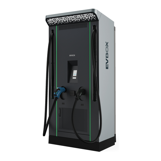
5. Product features 5. Product features 5.1. Product parts presentation 1. Charger status LED. 2. CHAdeMO connector (depending on the configuration). 3. Auto retractable cable. 4. LED lighting. 5. Touchscreen. 6. CCS connector. 7. Type 2 socket (depending on the configuration). -
Page 16: Technical Specifications
6. Technical specifications 6. Technical specifications Electrical data Table 2. Input Technical data Characteristic Supply voltage 3 phases + PE, 480 Vac Input voltage range 480 Vac +/- 10% (60 Hz) Maximum rated input power Installation side is 125% of nominal input power Nominal input power 111 kVA Nominal input current... - Page 17 6. Technical specifications Table 5. General Technical data Characteristic DC connection standard CHAdeMO 1.0 / COMBO DIN70121 ISO1518 DC cable length 9.84 ft (3.80 m) DC plug type (Combo 1) CCS - Type 1 DC plug type (CHAdeMO) JEVS G105 - CHAdeMO Network connection GPRS or Ethernet / OCPP 1.6 Mechanical data...
- Page 18 6. Technical specifications Technical data Characteristic Altitude < 3280 ft (1000 m) Ventilation Force air cooled...
-
Page 19: Prepare For Installation
7 at the beginning of this manual before you install, service or use the Troniq 100 charging station. The installer must ensure that the charging station is installed in accordance with the relevant country-specific standards and local regulations. -
Page 20: Cooling
In case of installation in a closed building, the room must have a system of permanent renewal of the air with a minimum air flow of 5,283 gal/min (1,200 m /h). The ventilation areas must not be blocked. Troniq 100 Airflow : Air outlet. : Air inlet 7.5. Clearance... -
Page 21: Clamping Kit
In order to ensure proper installation, and therefore durability of our products, the use of the clamping kit is recommended. It is sold separately by EVBox. Clamping kit supports the charger and contains holes to seal screw anchor in order to fix the charger. -
Page 22: Installation Without Clamping Kit
7. Prepare for installation Presence of sidewalk • No sidewalk: clamping kit has to be raised compared to the foundations in order to comply with American with Disabilities Act (ADA) regulation. No sidewalk 7.7. Installation without clamping kit For installation using not clamping kit, prepare the foundations according the to clamping kit diagram Clamping kit on page 50... -
Page 23: Foundations
7. Prepare for installation 7.8. Foundations Observe the following rules regarding the foundations: • Foundations must be carried out in accordance with local regulations. • Concrete characteristics must be calculated regarding the technical data of the charging station. • The concrete should be frost proof. •... -
Page 24: Phase Rotation
Ground impedance must be lower than 20 ohms in dry conditions. 7.10.2. Phase rotation In case of several Troniq 100 in the site location, to avoid overloading the first phase, it is recommended to rotate the phase as below. 7.10.3. Grounding instructions This unit is to be connected to a grounded, metal, permanent wiring system;... -
Page 25: Install The Clamping Kit
8. Install the clamping kit 8. Install the clamping kit 8.1. Handle the clamping kit Clamping kit can be handled with: • Lifting ring, • Forklift. Note: • Clamping kit weight is 660 lbs (400kg). • Use lifting device to support the weight of the clamping kit. Handling with lifting ring Use the integrated lifting ring to handle and place the clamping kit: Handling with forklift... -
Page 26: Place The Clamping Kit
8. Install the clamping kit 8.2. Place the clamping kit 8.2.1. With sidewalk Place the clamping kit in sidewalk configuration 1. Dig a hole according to the clamping kit structure and the calculations for foundations. 2. Install the cable ducts. 3. -
Page 27: Without Sidewalk
8. Install the clamping kit 7. Insert the four M12 threaded rods in the clamping kit. 8.2.2. Without sidewalk 1. Dig a hole according to the clamping kit structure and the calculations for foundations. 2. Install the cable ducts. 3. Start pouring concrete in the hole. 4. - Page 28 8. Install the clamping kit 7. Insert the four M12 threaded rods in the clamping kit.
-
Page 29: Install The Troniq 100
9. Install the Troniq 100 9. Install the Troniq 100 9.1. Remove the aluminum covers 9.1.1. Remove the aluminum covers on front side 1. Open the front door of the charging station. 2. Remove the two screws that maintain the upper aluminum cover. - Page 30 9. Install the Troniq 100 3. Remove the upper aluminum cover. 4. Remove the two screws and two nuts of the lower aluminum cover.
-
Page 31: Remove The Aluminum Covers On Rear Side
9. Install the Troniq 100 5. Remove the lower aluminum cover. 9.1.2. Remove the aluminum covers on rear side 1. Open the rear door of the charging station. - Page 32 9. Install the Troniq 100 2. Remove the two screws that maintain the upper aluminum cover. 3. Remove the upper aluminum cover.
-
Page 33: Handling
9. Install the Troniq 100 4. Remove the two screws and two nuts of the lower aluminum cover. 5. Remove the lower aluminum cover 9.2. Handling WARNING: • Always transport charger in upright position. -
Page 34: Placing
The center of gravity of the charger is high, be careful when handling. • Do not handle the charger by the top. With a base shaped like a pallet, Troniq 100 can be handled by a forklift. Troniq 100 base Lifting slings can be used to place the charging station: •... - Page 35 9. Install the Troniq 100 WARNING: Put up caution tape and warning sings to mark working areas. Make sure that connection of the electrical current cannot occur during installation. Make sure no unauthorized persons enter the working areas. 1. Handle the EVBoxTroniq 100 to its location.
-
Page 36: Electrical Connections
(according with the NFPA 70) Note: EVBox can provide in option M12 quick connector for AWG3/0 in option (see spare part list DCA006277). Connect the AC cables to the terminal. Note: To prevent from rodent intrusion and water ingress, it is possible to use retardant flame expensive foam. - Page 37 9. Install the Troniq 100 Protective earth connection Terminal Terminal Conductor Size Torque diameter Minimum AWG6. Protective earth cable shall be at minimum the 0.51 in (13 stranded 12 mm cross section cable of the main AC cables. (according with the...
-
Page 38: Commissioning
10. Commissioning 10. Commissioning 10.1. Danger: Risk of electric shock • Even if D1 and/or D3 is OFF, power supply is still present on the charger before servicing, switch off power at main breaker. 10.2. Start procedure 1. Switch circuit breaker D3 to ON. 2. -
Page 39: Use The Evbox Troniq 100
1. Welcome screen:The welcome screen offers the choice to select the language or to start a charging sessions. 2. Selection of connector type: If the EVBox Troniq 100 is set up with two different connector types, select the appropriate connector. - Page 40 11. Use the EVBox Troniq 100 3. Method of payment:If the EVBox Troniq 100 has a contact-less payment terminal, select your payment method. Otherwise, the RFID Tag method will be set as default. Depending on the product configuration, one of the two options can be set by default.
- Page 41 11. Use the EVBox Troniq 100 5. Contactless payment process:Follow the payment terminal instructions 6. RFID Tag process:If you chose RFID Tag as the payment authentication method, or if it is the default setting, swipe your card against the screen as shown on the HMI screen, then wait for validation.
- Page 42 11. Use the EVBox Troniq 100 7. Acceptance:The payment has been accepted.
-
Page 43: Stop Charging Evboxtroniq 100
11. Use the EVBox Troniq 100 8. Once connected, the charger will synchronize with your vehicle. 9. Charging session will carry on until you stop charging, or charge is completed. 11.2. Stop charging EVBoxTroniq 100... - Page 44 11. Use the EVBox Troniq 100 1. Stop the charge:Click on "STOP CHARGE" to stop the charging session. 2. Authentication:If you have been authenticated for the first time using a NFC (Near Field Communication) bank card, re-enter your payment method on terminal in order to be authorized to...
-
Page 45: State Of The Evboxtroniq 100
11. Use the EVBox Troniq 100 3. Authentication: If you have been authenticated by RFID Tag, you will be invited to swipe your card on the screen. 4. Vehicle unplugged:Once the vehicle has been unplugged, the total session amount will be displayed. - Page 46 11. Use the EVBox Troniq 100 1. If the event the EVBox Troniq 100 is out of order, the following screen will be displayed, and the charger LED will turn yellow. You may call the maintenance service. 2. Charger ready:Once the emergency stop button is back to its position, please validate the system restart by pressing "HOME".
-
Page 47: Cable Management System
11. Use the EVBox Troniq 100 11.4. Cable management system PINCH POINT When using cable management system, keep hands clear of rollers. Failure to these instruction can result in injury. -
Page 48: Decommissioning
If an operator uncovers the aluminum cover, operator needs to de-energize before (D1 & D8). Removal is the reverse of the installation procedure (see Install the Troniq 100 on page 25). Dispose of the charging station in a responsible manner. -
Page 49: Appendix
13. Appendix 13. Appendix 13.1. Installation report To ensure we will be able to go through the commissioning process, we ask for a report of the installation of the equipment, stating that it is finished and the result is the one expected at the end of the installation process, as described in the installation manual. - Page 50 13. Appendix Verifications Result Comments Validate that the door locks are correctly closed to guarantee sealing against water ingress. Confirm no evidence of humidity or water ingress inside the charger. Confirm the door hinges are correctly adjusted. Verify visually the cables and cabling inside the charging unit are acceptable.
- Page 51 13. Appendix Verifications Result Comments With all circuit breakers down, Switch ON circuit breaker D3, with the door OPEN, verify that the LEDs are lit RED that the display screen is ON. Update software if needed. Close the door and verify that the LEDs are lit RED and that the screen displays "CHARGER UNAVAILABLE"...
- Page 52 13. Appendix Verifications Result Comments Verify that all the LED indicators are light in green a there is not any abnormal noise. Test a normal client operation of the unit using a badge. Note any modifications undertaken during the commissioning (disconnecting earth cable, replacement of the SO-DIMM…): Validation location Date...
-
Page 53: Troniq100 - Dimensions
13. Appendix 13.2. Troniq100 - Dimensions... -
Page 54: Clamping Kit
13. Appendix 13.3. Clamping kit... - Page 55 13. Appendix...
-
Page 56: Electrical Diagrams
13. Appendix 13.4. Electrical diagrams... - Page 57 13. Appendix...
- Page 58 13. Appendix...
- Page 59 13. Appendix...
- Page 60 13. Appendix...
- Page 61 13. Appendix...
- Page 62 13. Appendix...
- Page 63 13. Appendix...
- Page 64 13. Appendix...
- Page 65 13. Appendix...
- Page 66 13. Appendix...
- Page 67 13. Appendix...
- Page 68 13. Appendix...
- Page 69 13. Appendix...
- Page 70 13. Appendix...
- Page 71 13. Appendix...
- Page 72 13. Appendix...
- Page 73 13. Appendix...
- Page 74 13. Appendix...
- Page 75 13. Appendix...
- Page 76 13. Appendix...
- Page 77 13. Appendix...
- Page 78 13. Appendix...
- Page 79 13. Appendix...
- Page 80 13. Appendix...
- Page 81 13. Appendix...
- Page 82 13. Appendix...
- Page 84 D001654AA0.1.0B5 © EVBox Bordeaux...
Need help?
Do you have a question about the Troniq 100 and is the answer not in the manual?
Questions and answers