Helmer Scientific i Series Service Manual
Undercounter freezer
Hide thumbs
Also See for i Series:
- Operation manual (30 pages) ,
- Service manual (89 pages) ,
- Service and maintenance manual (76 pages)
Table of Contents
Advertisement
Quick Links
Undercounter Freezer Service Manual
i.Series
and Horizon Series™
®
HELMER SCIENTIFIC
14400 Bergen Boulevard
Noblesville, IN 46060 USA
PH +1.317.773.9073
FAX +1.317.773.9082
USA and Canada 800.743.5637
360142-D/D
Model Group
i.Series
Plasma Storage
iPF105 (Version D)
Laboratory
iLF105 (Version D)
Horizon Series
HPF105 (Version D)
HLF105 (Version D)
0086
ISO 13485:2003 CERTIFIED
Advertisement
Table of Contents
Troubleshooting

Related Manuals for Helmer Scientific i Series


Summary of Contents for Helmer Scientific i Series
- Page 1 Horizon Series Plasma Storage iPF105 (Version D) HPF105 (Version D) Laboratory iLF105 (Version D) HLF105 (Version D) HELMER SCIENTIFIC 14400 Bergen Boulevard Noblesville, IN 46060 USA PH +1.317.773.9073 0086 FAX +1.317.773.9082 USA and Canada 800.743.5637 360142-D/D ISO 13485:2003 CERTIFIED...
- Page 2 Helmer Scientific. Helmer Scientific assumes no responsibility or liability for any errors or inaccuracies that may appear in the informational content contained in this material. For the purpose of clarity, Helmer Scientific considers only the most recent revision of this document to be valid.
-
Page 3: Table Of Contents
Contents Section I: General Information ........6 1 About this Manual . - Page 4 6.8.1 Remove the Door and Hinges ........... . . 17 6.8.2 Reverse the Cable Routing in the Door .
- Page 5 10.2 Rear ................49 10.3 Electrical Tray .
- Page 6 14.3 Check Optional Access Control System Battery ..........77 14.4 Clean the Freezer .
-
Page 7: Section I: General Information
1.4 Confidential / Proprietary Notices Use of any portion(s) of this document to copy, translate, disassemble or decompile, or create or attempt to create by reverse engineering or otherwise the information from Helmer Scientific products is expressly prohibited. Disclaimer This manual is intended as a guide to provide the operator with necessary instructions on the proper use and maintenance of certain Helmer Scientific products. -
Page 8: Safety
General Information Safety Includes general safety information for freezer operation. Labels Caution: Risk of damage Caution: Unlock all casters to equipment or danger to operator Caution: Hot surface Earth / ground terminal Caution: Shock/electrical Protective earth / ground hazard terminal 2.2 Avoiding Injury ► Review safety instructions before installing, using, or maintaining the equipment. -
Page 9: Control System
General Information Control System NOTE Service information varies depending on the control system. Helmer freezers have one of two control systems installed. The type of control system varies by model. 3.2.1 i.C³ Control System ® i.Series freezers are equipped with the i.C³ monitoring and control system. The i.C³ system combines temperature control and monitoring into a single interface. -
Page 10: Fill Temperature Probe Bottle
General Information 3.3.1 Fill Temperature Probe Bottle NOTE Temperature probes are fragile; handle with care. Remove all probes from bottle and remove bottle from bracket. Remove cap and fill with 4 oz (120 mL) of product simulation solution. Install cap and place bottle in bracket. Replace probes, immersing at least 2”... -
Page 11: Install Chart Paper
General Information 3.4.2 Install Chart Paper Press and hold C button. When stylus begins to move left, release button. The LED flashes to indicate current temperature range. When stylus stops moving, remove chart knob then move knob up and away. Place chart paper on chart recorder. -
Page 12: References And Compliance
General Information References and Compliance Alarm Reference If an alarm condition is met, an alarm activates. Some alarms are visual only; others are visual and audible. Some alarms are sent through the remote alarm interface. The table indicates if an alarm is audible (A), visual (V), or sent through the remote alarm interface (R). Alarm Alarm Type High Temperature... -
Page 13: Warranty
General Information Warranty Rel.i™ Product Warranty USA and Canada For technical service needs, please contact Helmer at 800-743-5637 or www.helmerinc.com. Have the model and serial number available when calling. 5.1.1 Rapid Resolution When a warranty issue arises it is our desire to respond quickly and appropriately. The service department at Helmer is there for you. -
Page 14: Outside Of Usa And Canada
General Information SERVICES IS LIMITED TO AN AMOUNT NOT TO EXCEED THE PRICE OF THE PARTICULAR GOODS OR SERVICES GIVING RISE TO THE LIABILITY. IN NO EVENT SHALL HELMER BE LIABLE FOR ANY INDIRECT, INCIDENTAL, CONSEQUENTIAL, OR SPECIAL DAMAGES, INCLUDING WITHOUT LIMITATION DAMAGES RELATED TO LOST REVENUES OR PROFITS, OR LOSS OF PRODUCTS. -
Page 15: Section Ii: I.series ® Models
i.Series® Models Section II: i.Series Models ® Product Configuration WARNING To prevent tipping: ► ensure the casters (if installed) are unlocked and the door is closed before moving the freezer. ► do not sit, lean, push or place heavy objects on upper door ledge. 6.1 Install Battery for Backup Power The monitoring system and chart recorder each have a battery system, enabling a period of continuous... -
Page 16: Automatic Defrost Cycle
i.Series® Models Automatic Defrost Cycle The number of programmed defrost events is dependent on environmental conditions and the frequency of usage. The recommended number of daily defrost cycles is three to four, at even intervals. Defrost events should take place when the freezer door is opened infrequently. NOTE Depending on the high temperature alarm setpoint and the actual temperature increase during the defrost cycle, frequent door openings may trigger repeated high temperature... -
Page 17: Move Drawers, Shelves, And Baskets
i.Series® Models 6.4 Move Drawers, Shelves, and Baskets Storage features. CAUTION ► Before moving drawers, ensure they are completely empty for safe lifting. ► Maximum basket, drawer, or shelf load is 100 lbs (46 kg). NOTE Before moving storage components, protect stored items in freezer from extended exposure to adverse temperature. -
Page 18: Level The Freezer
i.Series® Models Install shelf brackets Insert front brackets into standard at appropriate height. Tap front brackets downward to engage standards. Using a screwdriver, install front bracket retainers. Level the Freezer NOTE ► Leveling feet are optional. ► Helmer recommends the use of leveling feet (unless casters are installed) and wall and floor brackets (PN 400472-2) for stabilization. - Page 19 i.Series® Models Remove six screws holding the access panel and cover on the cabinet. Lay the panel in front of the cabinet, ensuring there is no strain on the power switch wires. Remove Remove Access panel Access panel cover Access Access panel panel cover Remove...
- Page 20 i.Series® Models Remove door latch / door catch. Remove two screws holding the door latch plates and spacer bar on the cabinet Set the latch plates and spacer bar aside. Cabinet Strike plate Remove 2 screws Door latch plate. With the door shut, remove the cover plate from both hinges. Remove the spring assembly from the lower hinge.
-
Page 21: Reverse The Cable Routing In The Door
i.Series® Models 11 Remove the upper hinge. Remove five screws attaching the upper hinge to the door and cabinet. Remove the upper hinge. Reverse the hinge manually (as if moving the hinge from a fully-closed to a fully-open position). Set the upper hinge aside. Door Cabinet Hinge... - Page 22 i.Series® Models Lay the door assembly face-down on a solid work surface. Remove remaining screws from both sides of the door assembly. Lift the inner door frame out of the outer door frame and set aside. A J-hook tool may be used along the bottom edge of the door assembly to lift the inner frame.
-
Page 23: Reinstall The Door And Hinges
i.Series® Models Left: Original cable routing (right-hinged door). Right: New cable routing (left-hinged door). Reposition the braided sleeve. Cut the zip ties (A) on the braided sleeve (B). Slide the sleeve and grommets (C) along the cables, towards the door. Slide the braided sleeve through the slot in the door and insert the door-side grommet into the hole in the door. - Page 24 i.Series® Models Door Hinge 2 screws (long) Hinge plate Shim Attach hinge to door (lower hinge shown). NOTE A second person should assist by supporting the door while the hinges are installed. Install the door on the cabinet. Lift the door to the cabinet. Align the holes in the hinges with the corresponding holes in the cabinet.
- Page 25 i.Series® Models Install the cable in the door. Slide the braided sleeve through the slot in the access panel. Install the grommet in the hole. Install the plug in the access panel on the opposite side. Allow enough slack (approximately 3”) in the braided sleeve between the door and the cabinet so the door can pivot open and closed without straining the cable.
-
Page 26: Stacked Undercounter Units
i.Series® Models Rotate the spring using a J-hook tool then insert pin (left-hinged door shown). 11 Switch AC ON/OFF switch ON. Switch battery switch ON. Close the lower front control panel. 12 Touch Mute to disable the high temperature alarm while freezer reaches operating temperature. 13 Verify the door is level and the hinges operate smoothly and the door seals tightly. -
Page 27: Settings
i.Series® Models Settings Through the i.C³ monitoring and control system, current settings may be viewed and changed. To view settings, touch Home, i.C³ APPS, Settings. Use a touch-drag motion to scroll up or down to display additional settings. NOTE ► If the Settings screen is password protected or if viewing settings for the first time, enter factory default password of “1234”. -
Page 28: Temperature Settings
i.Series® Models 7.2 Temperature Settings Temperature setpoint values are programmed at the factory. Setpoints can be viewed and changed through the i.C³ monitoring and control system. To view temperature setpoints, touch Home, i.C³ APPS, Settings. Details for each setpoint are displayed. Temperature Controller Programs screen. -
Page 29: Temperature Calibration
i.Series® Models Temperature Calibration Temperature calibration values are programmed at the factory. Calibration values can be viewed and changed through the i.C³ monitoring and control system. To view calibration settings, touch Home, i.C³ APPS, Settings. Details for each setting are displayed. Temperature Calibration screen. -
Page 30: Control Sensor Offset
i.Series® Models Touch + or – on the Upper Temperature spin box to increase or decrease the value to match the measured value. The message “New Setting Saved” appears next to the spin box. NOTE After saving the new temperature value, the displayed temperature may not match the new value. -
Page 31: Calibrate Compressor And Evaporator Probe
i.Series® Models 7.3.3 Calibrate Compressor and Evaporator Probe The compressor and evaporator temperature probes have been factory-calibrated. Calibration settings should not be changed unless directed by Helmer Technical Service. 7.3.4 Factory Default Settings Settings listed below may be simultaneously returned to factory default values. NOTE The factory default settings may not be the same as the settings that were factory- calibrated before the freezer was shipped. -
Page 32: Restore Factory Default Settings
i.Series® Models Setting Restored Value Control Relay Probe Failure Duty Cycle 100% Defrost Event #1 On/Off Defrost Event #1 Start Time 12:00 AM Defrost Event #2 On/Off Defrost Event #2 Start Time 8:00 AM Defrost Event #3 On/Off Defrost Event #3 Start Time 4:00 PM Defrost Event #4 On/Off Defrost Event #4 Start Time... -
Page 33: Test Alarms
i.Series® Models Test Alarms Test alarms to ensure they are working correctly. The freezer has alarms for chamber temperature, compressor temperature, door open (time), power failure, low battery, and power failure. 7.4.1 Automatic Chamber Temperature Alarm Test NOTE ► Test can be aborted by touching Cancel Test. ► Test takes less than five minutes. -
Page 34: Manual Chamber Alarm Test
i.Series® Models Cancel the test: Touch Home, i.C³ APPS, Temperature Alarm Test. Touch Cancel Test. NOTE When cancelling an automatic test, the message indicating the test is in progress clears immediately. If a setpoint was reached before the test was cancelled, the alarm activates and clears as described earlier. -
Page 35: Upgrade System Firmware
i.Series® Models 7.5 Upgrade System Firmware Helmer may occasionally issue updates for the i.C³ firmware. Follow upgrade instructions included with the firmware update. Calibrate the Touchscreen The i.C³ touchscreen has been calibrated at the factory to ensure that when the screen is touched, the desired key touch is selected. -
Page 36: Maintenance
i.Series® Models Maintenance NOTE ► Refer to the operation manual for the preventive maintenance schedule. ► Before performing maintenance, protect items in freezer from extended exposure to adverse temperature. ► Allow freezer temperature to stabilize at setpoint after performing service or after extended door opening. -
Page 37: Check Monitoring System Battery
i.Series® Models 8.3 Check Monitoring System Battery On all i.C³ screens, the Battery icon will appear in the header bar when the system is running on battery power and the screen brightness will automatically be reduced. The monitoring system will automatically disable some features to extend battery life. Check the battery: Switch AC ON/OFF switch OFF. -
Page 38: I.c³ ® Touchscreen
i.Series® Models Cap bottle tightly to minimize evaporation. Place bottle in bracket. Replace probe, immersing at least 2” (50 mm). 8.4.6 i.C³ Touchscreen ® Clean touchscreen with a soft, dry cotton cloth. Defrost the Unit Cooler Defrost events may be scheduled to occur at specific times. A defrost event can be triggered on demand without affecting a programmed defrosting schedule. -
Page 39: Remove The Unit Cooler Cover
i.Series® Models 8.6.1 Remove the Unit Cooler Cover Switch AC ON/OFF switch OFF. Switch battery switch OFF. Remove the rear protective cover (G) on the rear of the cabinet. Loosen four screws Slide the cover up and remove Cut the wire ties securing the drain line to the cabinet On the back of the cabinet, peel the putty back to expose the drain tube (H) and drain heater (E). -
Page 40: Troubleshooting
i.Series® Models Troubleshooting CAUTION Review all safety instructions prior to troubleshooting. Refer to Section I, Item 2 (Safety). General Operation Problems Problem Possible Cause Action A drawer or basket Debris in the drawer ► Pull the drawer or basket out and confirm the does not slide easily. -
Page 41: Chamber Temperature Problems
i.Series® Models Chamber Temperature Problems Problem Possible Cause Action The chamber Monitor probe is not ► Check the chamber temperature calibration. temperature displayed calibrated. Change the calibration if necessary. is higher or lower ► Test the monitor probe connections. Secure the Connections for the than the actual monitor probe are... -
Page 42: Alarm Activation Problems
i.Series® Models Problem Possible Cause Action The chamber Temperature monitor/ ► Confirm the temperature controller or monitor/ temperature does not control board is faulty. control board is operating correctly. Replace it if stabilize at the freezer necessary. setpoint. Condensing unit fan is ► Check the condensing unit fan connections. - Page 43 i.Series® Models Problem Possible Cause Action The High Temperature Connections for the ► Check the monitor probe connections. Secure the alarm activates when monitor probe are connections if necessary. the door is opened, loose. then clears shortly Monitor probe is ► Test the probe.
- Page 44 i.Series® Models Problem Possible Cause Action The Door Open Door is not closing ► Clean hinges if debris is present. alarm is activating completely. ► Confirm door is aligned. ► Confirm hinge spring and/or pin are not damaged. sporadically. Replace hinge (lower only) if necessary. ► Confirm the door gasket seals completely.
- Page 45 i.Series® Models Problem Possible Cause Action The condenser alarm Refrigerant level is too ► Check refrigeration lines for leaks and repair if is active. low. necessary. Check refrigerant level. Recharge if low. Connections for ► Test the probe connections. Secure the the condenser connections if necessary.
-
Page 46: Testing Problems
i.Series® Models 9.4 Testing Problems Problem Possible Cause Action The automatic Connections for the ► Test the monitor probe connections. Secure the temperature tests do monitor probe are connections if necessary. not work. loose. Monitor probe is ► Test the monitor probe. Replace the probe if faulty. - Page 47 i.Series® Models Problem Possible Cause Action After a defrost cycle, Not enough time has ► Allow approximately 20 minutes after the end no water flows into elapsed since the end of the defrost cycle to check for water in the the water evaporation of the defrost cycle.
-
Page 48: Parts
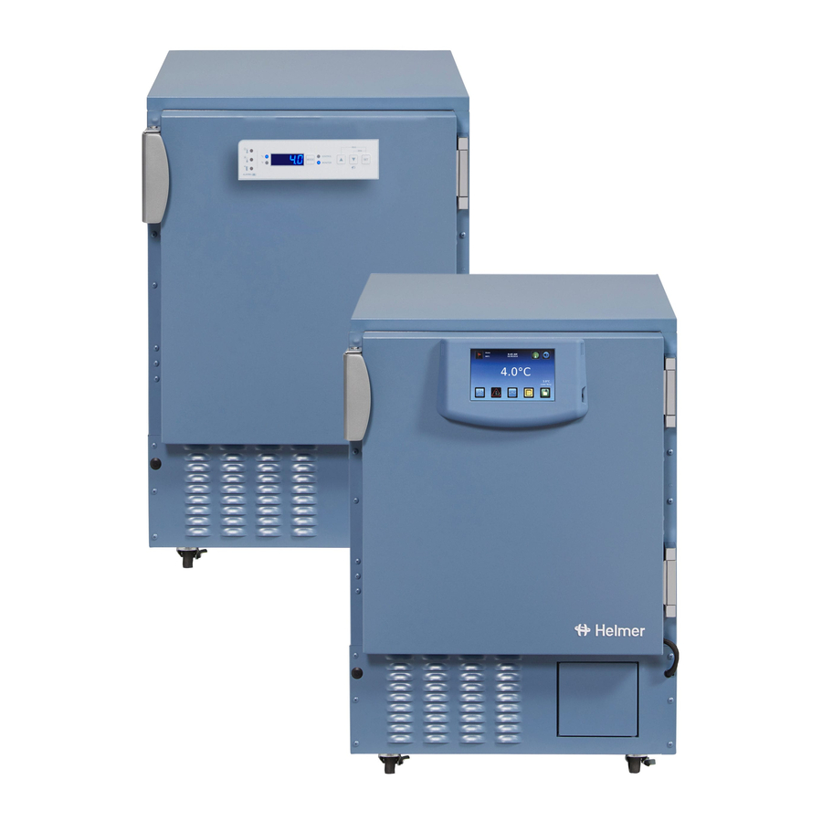
i.Series® Models Parts NOTE ► Before replacing parts, protect items in freezer from extended exposure to adverse temperature. ► Allow freezer temperature to stabilize at setpoint after replacing parts or after extended door opening. 10.1 Front 10.1.1 Control System Display Left: Front view, LCD touchscreen. -
Page 49: Control And Monitoring
i.Series® Models NOTE ► The i.C³ display assembly is sensitive to static electricity and can be damaged by electrostatic discharge. Use proper ESD precautions when handling the display assembly. ► Although the touchscreen and display board may be replaced independently of the i.C³... -
Page 50: Access Control Option
i.Series® Models 10.1.4 Access Control Option Access Control features (iPF105 model shown). Schematic Label Description Part Number Label Door handle (includes manual keyed lock) 322000-1 Magnetic lock assembly (includes magnet and door handle) 800139-1 Backup battery key switch 401220-1 10.2 Rear ILF105 2000000 Version D... -
Page 51: Electrical Tray
i.Series® Models Schematic Label Description Part Number Label Drain line assembly 400910-1 Power connector Cover for communication ports and remote alarm shown contacts Rear cover 321184-1 Remote alarm contacts USB port 120638 RJ-45 Ethernet port 800008-2 RS-232 COM port (optional) shown Condensate evaporator tray Power cable (with connector) North American models... -
Page 52: Electrical Tray Components
i.Series® Models 10.3.1 Electrical Tray Components Electrical tray features. Schematic Label Description Part Number Label Power supply board 800035-1 Compressor relay 115 V: 120426 230 V 50 Hz: 120669 230 V 60 Hz: 120671 i.C³ control board 800034-1 Power line filter 115 V: 120299 230 V: 120677 shown... -
Page 53: Interior
i.Series® Models 10.4 Interior Storage features. Schematic Label Description Part Number Label Door Stainless steel: 800063-2 Powder coated without Access Control: 800063-1 Powder coated with Access Control: 800144-1 Mullion heater (behind strike 115 V: 800081-1 plates) 230 V: 800106-1 Drawer (blood bank model) 400854-3 Door switch 120380... -
Page 54: Unit Cooler
i.Series® Models 10.4.1 Unit Cooler Unit cooler interior features. Schematic Label Description Part Number Label Unit cooler assembly 115 V: 120592 230 V: 120657 Fan guard Unit cooler fan motor 115 V: 120540 230 V: 120658 Control probe 800048-1 Defrost heater 115 V: 120633 230 V: 120659 Defrost heater limit thermostat... -
Page 55: Door And Hinge
i.Series® Models 10.6 Door and Hinge Hinge, hinge spring and pin assembly, and door handle with key lock. NOTE Spring tension is controlled at the point where the pin is stopped by the side plate (C, D). Label Description Part Number Hinge, covered, edge mount 220506 Hinge, uncovered, without spring assembly Hinge, uncovered, spring and pin assembly... -
Page 56: Schematics
i.Series® Models Schematics 11.1 iPF and iLF Models; 105 Configuration 360142-D/D... - Page 57 i.Series® Models Control Control Monitor 360142-D/D...
-
Page 58: Section Iii: Horizon Series™ Models
Horizon Series™ Models Section III: Horizon Series™ Models Product Configuration WARNING To prevent tipping: ► ensure the casters (if installed) are unlocked and the door is closed before moving the freezer. ► do not sit, lean, push or place heavy objects on upper door ledge. 12.1 Install Battery for Backup Power The monitoring system has a battery system, enabling a period of continuous operation if power is lost. -
Page 59: Schedule Defrost Events
Horizon Series™ Models 12.2 Schedule Defrost Events Defrost events may be scheduled to occur at specific times. Access to the defrost controller is available from the front of the freezer, in the pull-out components tray. Kick plate (removed), and pull-out components tray (open). Specify the number of defrost events to execute per day, as well as the time at which to initiate each defrost cycle. -
Page 60: Set Current Time
Horizon Series™ Models 12.2.1 Set Current Time Switch the AC ON/OFF switch OFF. Turn the Alarm Disable key switch OFF. Remove the kick plate and pull out the electrical tray. Rotate the time adjustment ring clockwise until the current time indicators show the current time. Push the electrical tray in and replace the kick plate. -
Page 61: External Monitoring Devices
Horizon Series™ Models 12.3 External Monitoring Devices The remote alarm interface is a relay switch with three terminals: ► Common (COM) ► Normally Open (NO) ► Normally Closed (NC) Terminals are dry contacts and do not supply voltage. Interface circuit is either normally open or normally closed, depending on terminals used. -
Page 62: Move Slides And Brackets
Horizon Series™ Models Remove a shelf With one hand, lift front edge of the shelf from the front brackets. With the other hand, reach under the shelf and bump rear edge of the shelf upward to disengage rear brackets. Install a shelf Insert shelf into chamber, placing it on brackets. -
Page 63: Reverse Door Hinge And Handle
Horizon Series™ Models 12.8 Reverse Door Hinge and Handle NOTE ► Before reversing door hinge and handle, protect stored items in freezer from extended exposure to adverse temperature. ► Freezer must be on the floor or on an elevated work surface with enough space in front of the freezer to lay the door face-down for disassembly. - Page 64 Horizon Series™ Models Remove the door handle assembly. Remove four screws holding the door handle assembly on the door. Set the door handle assembly aside. Remove Door handle assembly. Remove door latch / door catch. Remove two screws holding the door latch plates and spacer bar on the cabinet Set the latch plates and spacer bar aside.
-
Page 65: Reverse The Cable Routing In The Door
Horizon Series™ Models 10 Remove the lower hinge. Support the door. Remove five screws attaching the lower hinge to the door and cabinet. Remove the lower hinge. Reverse the hinge manually (as if moving the hinge from a fully-closed to a fully-open position). Set the lower hinge aside. - Page 66 Horizon Series™ Models Label Description Outer door frame Data cable (gray) Cable exit (corner of door) Additional cable slack Lay the door assembly face-down on a solid work surface. Remove remaining screws from both sides of the door assembly. Lift the inner door frame out of the outer door frame and set aside. A J-hook tool may be used along the bottom edge of the door assembly to lift the inner frame.
-
Page 67: Reinstall The Door And Hinges
Horizon Series™ Models Left: Original cable routing (right-hinged door). Right: New cable routing (left-hinged door). Route the data cable out of the door. Slide the data cable through the slot in the door. Insert the door-side grommet into the hole in the door. Reinstall the inner door frame inside the outer door frame. - Page 68 Horizon Series™ Models Cabinet Hinge 3 screws (short) Attach hinge to cabinet (lower hinge shown). Align the door and tighten screws. Support the door so the top edge of the door is level. Level the door using a shim if necessary. Tighten all screws attaching both hinges to the door and to the cabinet.
- Page 69 Horizon Series™ Models 10 Install the hinge spring and pin assembly. Close the door. Assemble the hinge spring assembly for the left side of the door (Figure A). Orient the bend in the coil toward the front of the freezer (Figure B). Slide the internal hex cap (with washer) on to the upper hex bolt in the lower hinge.
-
Page 70: Stacked Undercounter Units
Horizon Series™ Models 13 Press the Mute button to disable the high temperature alarm while freezer reaches operating temperature. 14 Verify the door is level and the hinges operate smoothly and the door seals tightly. 12.9 Stacked Undercounter Units CAUTION ► For a stacked configuration, both units must have leveling feet installed. ► The back brace bars and front stabilizing brackets must be installed [PN 400821-1 (blue) or 400821-2 (stainless steel)]. -
Page 71: Settings
Horizon Series™ Models Settings Through the Horizon Series monitoring and control system, current settings may be viewed and changed. NOTE ► Control Sensor Offset and Hysteresis settings are factory-preset and should not be changed unless directed by Helmer Technical Service. ► Changing temperature settings affects operation of the freezer. -
Page 72: Display Minimum And Maximum Monitor Temperature Recordings
Horizon Series™ Models 13.2 Display Minimum and Maximum Monitor Temperature Recordings ► This feature is standard on Horizon Series™ models with serial numbers of 2015494 NOTE or higher. Some exceptions may exist. For confirmation on your unit, please contact Helmer Technical Service. ► Units that do not include the minimum and maximum recording feature will not display .C or .F when entering the program mode. -
Page 73: Freezer Setpoint
Horizon Series™ Models 13.3 Freezer Setpoint NOTE Default setpoint is -30.0 °C Change the setpoint if: ► Your organization requires a chamber temperature other than -30.0 °C. Change setpoint. On the monitoring system, press and release SEL to change to Control mode. The CONTROL lamp will illuminate. -
Page 74: Temperature Alarm Setpoints
Horizon Series™ Models 13.5 Temperature Alarm Setpoints Temperature alarm setpoints specify the temperature at which an alarm activates. 13.5.1 High Temperature Alarm Setpoint Press and hold the Up and Down Arrows simultaneously for 3 seconds to enter program mode. The LED Display will show .C or .F to indicate Celsius or Fahrenheit. Press SEL until HIGH TEMP and MONITOR lamps flash. -
Page 75: Control Sensor Offset
Horizon Series™ Models Enter the new offset value: Press and hold the Up and Down Arrows simultaneously for 3 seconds to enter program mode. The display will show .C or .F to indicate Celsius or Fahrenheit. Press SEL until only the MONITOR lamp flashes. Hold SET, then press Up or Down Arrow to change the monitor offset. -
Page 76: Test Alarms
Horizon Series™ Models 13.7 Test Alarms Test alarms to ensure they are working correctly. The freezer has alarms for chamber temperature, power failure, and door open (time). NOTE Before testing alarms, protect items in freezer from extended exposure to adverse temperature. -
Page 77: Maintenance
Horizon Series™ Models Maintenance NOTE ► Refer to the operation manual for the preventive maintenance schedule. ► Before performing maintenance, protect items in freezer from extended exposure to adverse temperature. ► Allow freezer temperature to stabilize at setpoint after performing service or after extended door opening. -
Page 78: Check Optional Access Control System Battery
Horizon Series™ Models 14.3 Check Optional Access Control System Battery During an AC power failure, the Access Control backup battery provides backup power to power the magnetic Access Control lock. Test the Access Control backup battery to ensure it is working properly. Check the battery: Ensure Access Control battery key switch is switched ON. Switch AC ON/OFF switch OFF. -
Page 79: Unit Cooler Cover Removal And Installation
Horizon Series™ Models 14.5 Unit Cooler Cover Removal and Installation If unit cooler cover is not removed as detailed in this procedure the drain port may be damaged. Improper drainage may result in excessive icing and freezer’s inability to maintain temperature. Required tools: ► 5/16”... -
Page 80: Install The Unit Cooler Cover
Horizon Series™ Models Remove the drain tube (H) by pulling it downward. The drain tube should separate from the fan tube (D) at the 90° elbow, leaving the fan tube (D) attached to the fan (C). The section of the drain tube inside the cabinet should separate from unit cooler drain port (B). Gently twist the drain tube from left to right to separate it from the unit cooler drain port. -
Page 81: Troubleshooting
Horizon Series™ Models Troubleshooting CAUTION Review all safety instructions prior to troubleshooting. Refer to Section I, Item 2 (Safety). 15.1 General Operation Problems Problem Possible Cause Action A drawer or basket Debris in the drawer ► Pull the drawer or basket out and confirm the does not slide easily. -
Page 82: Chamber Temperature Problems
Horizon Series™ Models 15.2 Chamber Temperature Problems Problem Possible Cause Action “Prob” appears on Connections for the ► Check the probe connections. Secure the the display, but the monitor probe are connections if necessary. chamber temperature loose. is set correctly. Monitor probe wiring ► Check the continuity of the probe wiring and is an open circuit. - Page 83 Horizon Series™ Models Problem Possible Cause Action The chamber Monitor/control board ► Confirm the temperature controller or monitor/ temperature does not is faulty. control board is operating correctly. Replace it if stabilize at the freezer necessary. setpoint. Compressor starting ► Confirm the relay is operating correctly. Replace relay is faulty.
-
Page 84: Alarm Activation Problems
Horizon Series™ Models 15.3 Alarm Activation Problems Problem Possible Cause Action The freezer is in an Alarm system is faulty. ► Confirm the circuit board and line connections are alarm condition, but functioning correctly. the appropriate alarm ► Replace parts with those included in the control Monitor/control board is not audible or is faulty. - Page 85 Horizon Series™ Models Problem Possible Cause Action The Door Open Door is not closing ► Clean hinges if debris is present. alarm is activating completely. ► Confirm door is aligned. ► Confirm hinge spring and/or pin are not damaged. sporadically. Replace hinge (lower only) if necessary.
-
Page 86: Condensation And Icing Problems
Horizon Series™ Models 15.4 Condensation and Icing Problems Problem Possible Cause Action There is excessive Humid air is entering ► Confirm the freezer is level, and the door is water in the water the chamber aligned, closing tightly, and sealing correctly. evaporation tray Correct issues as necessary. -
Page 87: Parts
Horizon Series™ Models Parts NOTE ► Before replacing parts, protect items in freezer from extended exposure to adverse temperature. ► Allow freezer temperature to stabilize at setpoint after replacing parts or after extended door opening. 16.1 Front 16.1.1 Control System Display Top: Display with touchpad. -
Page 88: Control And Monitoring
Horizon Series™ Models 16.1.2 Control and Monitoring Schematic Label Description Part Number Label Horizon Series monitoring and control system Temperature chart recorder (standard on plasma freezer 500613-1 model, optional on laboratory model) Chart paper (52 sheets) 220419 Chart recorder backup battery 120218 shown 16.1.3 Lower Panel Lower panel features. -
Page 89: Access Control Option
Horizon Series™ Models 16.1.4 Access Control Option Access Control features (HPF105 model shown). Schematic Label Description Part Number Label Door handle (includes manual keyed lock) 322000-1 Keypad 800007-1 Magnetic lock assembly (includes magnet and handle) 800139-1 Backup battery key switch 401220-1 Backup battery (behind battery cover) 120628 16.2... -
Page 90: Electrical Tray
Horizon Series™ Models Schematic Label Description Part Number Label Nut flanges for brace bars used in stacking undercounter units Rear access port Drain line fan 115 V: 400909-1 230 V: 400909-2 Drain line heater 115 V: 120590 230 V: 120485 Drain line assembly 400910-1 Power connector Rear cover... -
Page 91: Electrical Tray Components
Horizon Series™ Models CAUTION Disconnect the freezer from AC power before accessing the electrical tray. 16.3.1 Electrical Tray Components Electrical tray features. Schematic Label Description Part Number Label Compressor relay 115 V: 120426 230 V 50 Hz: 120669 230 V 60 Hz: 120671 Temperature control transformer 115 V: 401097-1 230 V: 401098-1... -
Page 92: Interior
Horizon Series™ Models 16.4 Interior Interior features. Schematic Label Description Part Number Label Door Stainless steel without Access Control: 800064-2 Powder coated with Access Control: 800062-1 Powder coated without Access Control: 800064-1 Drawer (plasma freezer 400584-3 model) Door switch 120380 Mullion heater (behind strike 115 V: 800081-1 plates) 230 V: 800106-1... - Page 93 Horizon Series™ Models 16.4.1 Unit Cooler Left: Unit cooler with fan guard. Middle: Unit cooler fan. Right: Temperature control probe. Schematic Label Description Part Number Label Unit cooler assembly 115 V: 120592 230 V: 120657 Fan guard Unit cooler fan motor 115 V: 120540 230 V: 120658 Control probe...
-
Page 94: Door And Hinge
Horizon Series™ Models 16.5 Door and Hinge Hinge, hinge spring and pin assembly, and door handle with key lock. NOTE Spring tension is controlled at the point where the pin is stopped by the side plate (C, D). Label Description Part Number Hinge, covered, edge mount 220506 Hinge, uncovered, without spring assembly Hinge, uncovered, spring and pin assembly... - Page 95 Horizon Series™ Models 16.6 Side Access Panel Undercounter freezers feature easy access for servicing, removal, and replacement of the compressor and condenser. The compressor is accessible from the rear and the side. Side access panel. 360142-D/D...
-
Page 96: Schematics
Horizon Series™ Models Schematics 17.1 HPF and HLF Models; 105 Configuration (Without Access Control) MONITOR 360142-D/D... -
Page 97: Hpf And Hlf Models; 105 Configuration (With Access Control)
Horizon Series™ Models 17.1 HPF and HLF Models; 105 Configuration (With Access Control) MONITOR END OF MANUAL 360142-D/D... - Page 99 HELMER SCIENTIFIC 14395 Bergen Boulevard Noblesville, IN 46060 USA Phone +1 (317) 773-9073 Fax +1 (317) 773-9082 www.helmerinc.com...
Need help?
Do you have a question about the i Series and is the answer not in the manual?
Questions and answers