Table of Contents
Advertisement
Quick Links
Advertisement
Table of Contents
Troubleshooting

Subscribe to Our Youtube Channel
Related Manuals for AVERATEC 4100


Summary of Contents for AVERATEC 4100
- Page 1 AVERATEC User’s Manual...
- Page 2 Notice The information in this user’s manual is subject to change without notice. THE MANUFACTURER OR RESELLER SHALL NOT BE LIABLE FOR ERRORS OR OMISSIONS CONTAINED IN THIS MANUAL AND SHALL NOT BE LIABLE FOR ANY CONSEQUENTIAL DAMAGES, WHICH MAY RESULT FROM THE PERFORMANCE OR USE OF THIS MANUAL.
- Page 3 PREFACE Symbols and Conventions Protecting Your Computer - Avoid Abusive Handling and Adverse Environment Chapter Summaries 1. GETTING TO KNOW THE BASICS Performance Features System at a Glance Top View Front and Rear Views Side Views Bottom View AC Adapter LED Status Indicators Keyboard Features Function (Quick) Keys...
-
Page 4: Troubleshooting
Using Windows Power Options Windows’ Power Schemes Suspend Modes Power Button Action Low Battery Warning Power Manual Quick Access 4. UPGRADING YOUR COMPUTER Upgrading the System Memory 5. TROUBLE-SHOOTING First Step Audio Problems Hard Disk Problems Optical Drive Problems Display Problems Keyboard and Mouse Problems CMOS Battery Problems Memory Problems... -
Page 5: Using This Manual
Preface Using This Manual This User’s Manual contains general information about the hardware and software setup, troubleshooting, and technical specifications of the notebook computer. Symbols and Conventions The following conventions and symbols are used in this manual: When keys are to be pressed at the same time, a plus (+) symbol is used. For instance, Fn+F7 means holding Fn and F7 keys at the same time. - Page 6 Protecting Your Computer - Avoid Abusive Handling and Adverse Environment Following the advice below will help ensure that you get the most out of your Investment. Your computer will serve you well if you take good care of it. Do not expose the computer to direct sunlight or place it near sources of heat. Do not subject it to temperatures below 0 Do not expose the computer to magnetic fields.
-
Page 7: Chapter Summaries
Chapter Summaries The following is a summary of the available chapters and appendices in this manual. Chapter 1: Getting to Know the Basics In this chapter, you will learn the basic operations and features of your computer. It gives you a general understanding of the components of your computer. -
Page 8: Getting To Know The Basics
■ Chapter 1 Getting to Know the Basics GETTING TO KNOW THE BASICS This chapter introduces the features and components of the computer. -
Page 9: Performance Features
■ Chapter 1 Getting to Know the Basics Performance Features High Performance AMD Processor The notebook PC is equipped with a powerful Mobile AMD Sempron or Turnion64™ processor. Together with the latest system chipset and technologies, this notebook offers advanced PC performance. -
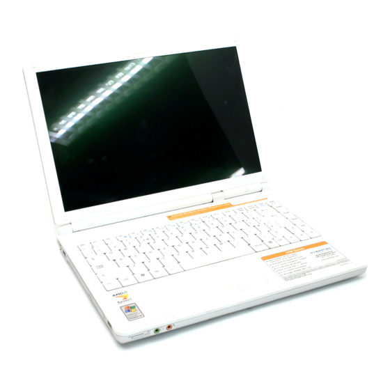
Page 10: System At A Glance
■ Chapter 1 Getting to Know the Basics System At A Glance Top View 1. AveraBrite™ LCD Display The panel is where the system content is displayed. 2. Keyboard The keyboard is used to enter data. It has an embedded numeric keypad and cursor control keys. (See Keyboard Section for details.) 3. - Page 11 ■ Chapter 1 Getting to Know the Basics Power Options > Advanced] menu. Press the power / suspend button again to return from the suspend mode. (See Chapter 3 for more details on system suspend function.) 6. Battery Saver Mode Button Pressing the key enables the system to lower its power usage;...
- Page 12 ■ Chapter 1 Getting to Know the Basics A Kensington-type security lock latches to this keyhole for anti-theft purpose. 6. Battery Pack The battery pack is a built-in power source for the notebook. 7. Power Jack (DC-in) The DC-out jack of the AC Adapter connects here and powers the computer. 8.
- Page 13 ■ Chapter 1 Getting to Know the Basics 6. Ethernet / LAN Port The port connects to a network hub via the RJ-45 cable and also conforms to the 10/100Base-TX transmission protocol. 7. TV (S-Video) Port The S-Video port permits you to redirect the screen output to a television set or any analog video playback device.
- Page 14 ■ Chapter 1 Getting to Know the Basics 2. System Device Cover The system’s processor with cooler assembly, Wireless LAN module, HDD and memory module are located under the case cover. The system memory can be upgraded to a larger capacity. (See Chapter 4 for instructions on a memory upgrade.) 3.
-
Page 15: Led Status Indicator
■ Chapter 1 Getting to Know the Basics LED Status Indicator The LED Status Indicator displays the operating status of your notebook. When a certain function is enabled, an LED will light up. The following section describes its indication. System & Power Status Indicators Graphic Indication Symbol... -
Page 16: Keyboard Features
■ Chapter 1 Getting to Know the Basics Keyboard Features Function Keys (Quick Keys) Graphic Action Symbol Fn + F3 Fn + F4 Fn + F5 Fn + F6 Fn + F7 Fn + F8 Fn + F9 Fn + F10 Fn + Num Fn + Scr Lk Press the Scroll Lock key and For various system controls, press the Fn (Function) key and the Fx key simultaneously. - Page 17 ■ Chapter 1 Getting to Know the Basics Windows Keys Your keyboard also has two Windows keys: 1. Start Key This key allows you to pull up the Windows Start Menu at the bottom of the taskbar. 2. Application Menu Key This key brings up the popup menu for the application, similar to a click of the right mouse button.
-
Page 18: Touch Pad
■ Chapter 1 Getting to Know the Basics Touch Pad The built-in touch pad, which is a PS/2-compatible pointing device, senses movement on its surface. As you move your fingertip on the surface of the pad, the cursor responds accordingly. The following items teach you how to use the touch pad: 1. -
Page 19: Graphic Subsystem
■ Chapter 1 Getting to Know the Basics Graphic Subsystem Your computer uses a high performance 13.3” active matrix TFT panel with high resolution for comfortable viewing. Adjusting the Display Brightness The notebook uses special key combinations, called hot keys, to control brightness. Press Fn+F7 to increase the brightness. -
Page 20: Audio Subsystem
■ Chapter 1 Getting to Know the Basics Audio Subsystem Your computer’s audio subsystem is Sound Blaster Pro-compatible. Adjusting the Volume Manually To increase the volume, press Fn+F9. To decrease the volume, press Fn+F8. Adjusting the Audio Volume in Windows 1. - Page 21 ■ Chapter 1 Getting to Know the Basics Modem Your computer comes with a 56K V.92 internal fax/modem and a phone jack (RJ-11), which is located on the left side of your computer. Use a telephone cable to connect the computer to the telephone wall outlet. Connecting the Modem 1.
- Page 22 ■ Chapter 1 Getting to Know the Basics Ethernet Your computer is equipped with a 10/100Base-TX Fast Ethernet network adapter. Connect the active LAN cable to the RJ-45 LAN port located on the right side of the computer. This allows you to access and transmit data in the local area network.
-
Page 23: Bios Setup And Security Feature
■ Chapter 2 Bios Setup and Security Feature BIOS SETUP AND SECURITY FEATURE In this chapter, you will learn how to enter the BIOS Setup Menu and manipulate various hardware control settings. You will also learn how to use the built-in security features. - Page 24 ■ Chapter 2 Bios Setup and Security Feature The Setup Utility is a hardware configuration program built into your computer’s BIOS (Basic Input/Output System). It runs and maintains a variety of hardware functions. It is a menu-driven software, which allows you to easily configure and change the settings.
-
Page 25: Entering The Bios Setup Screen
■ Chapter 2 Bios Setup and Security Feature Entering the BIOS Setup Screen First turn on the power. When the BIOS performs the POST (Power-On Self Test), press the F2 key quickly to activate the BIOS Setup Utility. Note: You may need to press F2 key fairly quickly. Once the system begins to load Windows, you may have to retry by rebooting the computer Leaving the BIOS Setup Screen When you have finished modifying the BIOS settings, exit the BIOS. -
Page 26: Modifying The Bios Settings
■ Chapter 2 Bios Setup and Security Feature Modifying the BIOS Settings The AMIBIOS setup main menu is subdivided into sub-menus. Each menu item is described in this section. Main Setup Under this menu, you may change time/date and view basic processor and system memory information. Item Selections / Description... -
Page 27: Boot Setup
■ Chapter 2 Bios Setup and Security Feature Enable [Enable]: The system automatically Backlight Disable reduces the LCD brightness when AC Saver power is removed and when the keyboard or touchpad has been idle for more than 10 minutes. [Disable]: The LCD Backlight Saver function is disabled. -
Page 28: Security Setup
■ Chapter 2 Bios Setup and Security Feature Security Setup ►Boot Settings Configuration Item Selections / Description Sub-menu Change Install or Change the Password Supervisor Password Change Install or Change the Password User Password Using Password Protection Two Levels of Password Protection are available. The BIOS provides both a Supervisor and a User password. -
Page 29: Exit Setup
■ Chapter 2 Bios Setup and Security Feature Exit Setup Item Selections / Description Sub-menu Saves After you have completed the BIOS Changes and settings, select this item to save all Exit settings, exit BIOS Setup utility, and reboot. New system settings will take effect on next power-up. - Page 30 ■ Chapter 3 Battery Power & Power Management BATTERY POWER & POWER MANAGEMENT In this chapter, you will learn the fundamentals of power management and how to use it to achieve longer battery life.
-
Page 31: The Battery Pack
■ Chapter 3 Battery Power & Power Management In this chapter, you will learn how to operate your notebook on battery power, how to handle and maintain the battery pack, and learn about the system’s power saving features. The LCD display, CPU and hard disk drive are the major hardware components that consume the most power. - Page 32 ■ Chapter 3 Battery Power & Power Management Battery Low-Power Warning Low Battery Warning Low battery condition occurs when battery power is reduced to 6%. The red battery status LED indicator blinks and the system beeps once every 16 seconds or so. Very Low Battery Warning Very Low battery condition occurs at 3 % power remaining.
-
Page 33: Installing And Removing The Battery Pack
■ Chapter 3 Battery Power & Power Management Installing and Removing the Battery Pack To Remove the Battery Pack: Place the notebook bottom-side up on a flat and secured surface. Push the latch and pull the battery’s hard case away from the notebook. -
Page 34: To Install The Battery Pack
■ Chapter 3 Battery Power & Power Management To Install the Battery Pack: Place the notebook bottom-side up on a flat and secured surface. Carefully insert the battery pack into the battery compartment of the notebook. Charging the Battery and Charging Time To charge the battery while it is in the notebook, plug the AC adapter into the notebook and an electrical outlet. -
Page 35: Checking The Battery Level
■ Chapter 3 Battery Power & Power Management Checking the Battery Level You can check the remaining battery power in the Windows battery status indicator, which is located at the lower right-hand corner of the task bar. (If you do not see a battery or AC-in icon on the task tray, go to Power Options Properties box and click on the Advanced tab. -
Page 36: Using Windows Power Options
■ Chapter 3 Battery Power & Power Management Using Windows Power Options Windows Power Management provides basic power saving features. In the Windows Power Options Properties [Start > Settings > Control Panel > Performance and Maintenance > Power Options] dialogue box, you may enter time-out values for display and hard disk drive. -
Page 37: Suspend Mode
■ Chapter 3 Battery Power & Power Management Suspend Mode Standby Suspend The system automatically enters this mode after a period of inactivity, which is set in the Power Schemes dialog box. In Standby mode, hardware devices, such as the display panel and hard disk, are turned off to conserve energy. -
Page 38: Power Button Action
■ Chapter 3 Battery Power & Power Management Power Button Action The notebook PC’s power button can be set to turn off the system or activate the suspend mode. Go to [Start > Settings > Control Panel > Performance and Maintenance > Power Options] and click on the Advanced tab. -
Page 39: Low Battery Warning
■ Chapter 3 Battery Power & Power Management Low Battery Warning You can define when and how the system warns you of its low battery condition. Go to the Alarms tab in the Power Options Properties box. If you wish to hear audible beeps, click on the Alarm Action button and put a check on Sound Alarm. -
Page 40: Power Menu Quick Access
■ Chapter 3 Battery Power & Power Management Power Menu Quick Access Instead of making specific selections in the Power Options Properties box, you can quickly and easily specify which pre-set power saving function you desire by left clicking on the Battery icon at the lower right-hand corner of the task bar. -
Page 41: Upgrading Your Computer
■ Chapter 4 Upgrading Your Computer UPGRADING YOUR COMPUTER In this chapter, you will learn how to upgrade the DRAM. Warning: We strongly recommend that you send your notebook back to the manufacturer for upgrading. When you upgrade your system, please turn off the power, disconnect the LAN and Modem cable first for your safety. -
Page 42: Upgrading The System Memory
■ Chapter 4 Upgrading Your Computer Upgrading the System Memory Many applications will generally run faster when the computer’s dynamic memory capacity is increased. The computer provides two DDR memory sockets. There is one located underneath the System Device Cover and another one located underneath the keyboard. - Page 43 ■ Chapter 4 Upgrading Your Computer Installing a memory module (DIMM) into the system To install the DIMM under the System Device Cover, do the following: Power OFF the notebook. Unplug the AC cord and all cables/devices attached to the notebook. Remove the battery.
- Page 44 ■ Chapter 4 Upgrading Your Computer Install the new DIMM module into the memory socket. The DIMM will only fit in one way. Insert the DIMM at an angle of approximately 30 degrees into the empty memory socket. Then press it firmly so that the contact edge is driven into the receiving socket.
- Page 45 ■ Chapter 4 Upgrading Your Computer To install the DIMM under the keyboard, do the following: Power OFF the notebook. Unplug the AC cord and all cables/devices attached to the notebook. Remove the battery. Place your hand on a large metal object momentarily to discharge any static electricity. Place the notebook on a flat surface and fully close the LCD lid.
- Page 46 ■ Chapter 4 Upgrading Your Computer If you need to remove an old DIMM from the socket, press out on the latches located on both edges of the socket at the same time. The DIMM should pop up to an angle of 30 degree (see diagram below).
-
Page 47: Trouble Shooting
■ Chapter 5 Trouble Shooting TROUBLE SHOOTING In this chapter, you will learn how to solve common hardware and software problems. - Page 48 ■ Chapter 5 Trouble Shooting Your computer has been fully tested and complies with the system specifications before shipping. However, incorrect operations and/or mishandling may cause problems. This chapter provides a reference for identifying and correcting common hardware and software problems that you may encounter.
-
Page 49: Audio Problems
■ Chapter 5 Trouble Shooting Audio Problems No speaker output - Software volume control is turned down in Microsoft Sound System or is muted. Double-click the speaker icon on the lower right corner of the taskbar to see if the speaker has been muted or turned down all the way. -
Page 50: Hard Disk Problems
■ Chapter 5 Trouble Shooting Hard Disk Problems The hard disk drive does not work or is not recognizable - Check the hard disk indicator LED. When you access a file, the LED lamp should light up momentarily. The HDD may be defective. If your computer has been subjected to static electricity or physical shock, you may have damaged the disk drive. -
Page 51: Optical Drive Problems
■ Chapter 5 Trouble Shooting Optical Drive Problems The optical drive does not work - Try rebooting the system. The disk is damaged or files are not readable. After you have inserted a CD-ROM disk, it may take a moment before you can access its content. The drive does not read any disks - The CD may not be properly seated in the tray. -
Page 52: Display Problems
■ Chapter 5 Trouble Shooting Display Problems The display panel is blank when the system is turned on - Make sure the computer is not in the Standby or Hibernate suspend modes. The display is turned off to conserve energy in these modes. The screen is difficult to read - The display resolution should at least be set to at least 1280x800 for optimal viewing. -
Page 53: Cmos Battery Problem
■ Chapter 5 Trouble Shooting CMOS Battery Problem A message “CMOS Checksum Failure” displays during the booting process or the time (clock) resets when booting - Try to reboot the system. If the message “CMOS Checksum Failure” appears during the booting procedure even after rebooting, it may indicate failure of the CMOS battery. -
Page 54: Modem Problems
■ Chapter 5 Trouble Shooting Modem Problems The built-in modem does not respond - Make sure the modem driver is loaded properly. Go to [Start > Settings > Control Panel > Printers and Other Hardware > Phone and Modem Options] and go to Modems tab. -
Page 55: Pc Card (Pcmcia) Problems
■ Chapter 5 Trouble Shooting PC Card / PCMCIA Problems PC Cards do not function- Make sure you have properly installed the driver for the card. Consult the card’s manual or contact the vendor for trouble-shooting. The PC card cannot be recognized - Make sure the card is fully inserted;... -
Page 56: Firewire (Ieee1394) And Usb 2.0 Problems
■ Chapter 5 Trouble Shooting FireWire (IEEE1394) and USB 2.0 Problems The USB device does not work - Check the settings in the Windows Control Panel. Make sure you have installed the necessary device drivers. Contact the device vendor for additional support. The IEEE1394 port does not work - Go to [Start >... -
Page 57: Appendix A Product Specification
■ Appendix A Product Specification PRODUCT SPECIFICATION... - Page 58 ■ Appendix A Product Specification Processor and Core Logic Processor Mobile AMD Turion or Sempron, 25W Low Power Core Logic Integrated chipset with video, audio, modem and USB 2.0 controllers. Integrated 333 / 400 MHz DDR1 interface System Memory Memory Type DDR SDRAM 333MHz, PC2700 Default 256 / 512MB, 2.5-Volt 64-bit bus...
-
Page 59: Lan / Ethernet
■ Appendix A Product Specification Audio Chipset Integrated audio controller Audio Codec Sound DirectSound 3D, EAX 1.0 & 2.0 compatible Capabilities A3D, I3DL2 compatible AC97 compatible 7.1 Multi-channel compatible (through S/PDIF) 2 Stereo Speakers Modem Chipset Integrated Modem Controller with MDC card, AC97 V2.2 Modem support V.92 / V.90 / K56flex for download data speed up to 56Kbps. -
Page 60: Keyboard & Touch Pad
■ Appendix A Product Specification FireWire IEEE1394(a) Chipset TI TSB43AB22A IEEE1394 OHCI Host Controller and Up to 400 Mbps Capabilities Expandable up to 63 devices in chains Storage Hard Drive 2.5-inch format hard disk drive DVD±R/±RW 5.25-inch format (12.7mm height) fixed module or Combo DVD+CD-RW Keyboard &... -
Page 61: Physical Specification
■ Appendix A Product Specification Battery Pack / AC Adapter Primary Li-Ion 6-Cell pack, 11.1V x 4400 mAh Battery Pack Low battery state with low battery warning beep Feature SmartPower II Power Management Smart Battery Compliant; low battery warning beep Long Battery Life Mode and Silent Mode Adapter Auto sensing AC-in 100~240V, DC-out 19V, 65W... -
Page 62: Appendix B Agency Regulatory Notices
■ Appendix B Agency Regulatory Notices AGENCY REGULATORY NOTICES... - Page 63 ■ Appendix B Agency Regulatory Notices Federal Communications Commission Notice This equipment has been tested and found to comply with the limits for a Class B digital device, pursuant to Part 15 of the FCC Rules. These limits are designed to provide reasonable protection against harmful interference in a residential installation.
- Page 64 ■ Appendix B Agency Regulatory Notices of the power cords listed below. To purchase a power cord (including one for a country not listed below) or a replacement ac adapter, contact your local dealer. U.S. and Canada The cord set must be UL-Listed and CSA-Certified or C-UL Listed. The minimum specifications for the flexible cord are (1) No.
- Page 65 ■ Appendix B Agency Regulatory Notices Do not disassemble the pack. Do not dispose of the battery pack in fire or water. To avoid risk of fire, burns, or damage to your battery pack, do not allow a metal object to touch the battery contacts.
- Page 66 ■ Appendix B Agency Regulatory Notices Zum Netzanschlua dieses Gerates ist eine geprufte Leitung zu verwenden. Fur einen Nennstrom bis 6A und einem Gerategewicht groBer 3kg ist eine Leitung nicht leichter als (1)H05VV-F, 3G, 0.75mm conductors einzusetzen. Die Steckdose muB nahe dem Gerat angebracht und leicht zuganglich sein. C AUTION! This p a rt is h ot.
-
Page 67: Year Limited Warranty
AVERATEC and will not be returned to the customer. The customer is responsible for shipping charges incurred upon sending the unit in for service to AVERATEC. -
Page 68: Six Month Limited Warranty
Applicable to new AVERATEC Batteries The limited warranty set forth on this warranty card is provided by AVERATEC, Inc. with respect to the AVERATEC brand Battery that you have purchased, when purchased and used with a AVERATEC brand notebook computer. - Page 69 Applicable to new AVERATEC Accessories The limited warranty set forth on this warranty card is provided by AVERATEC, Inc. with respect to the AVERATEC brand Accessory that you have purchased, when purchased and used with a AVERATEC brand notebook computer.
Need help?
Do you have a question about the 4100 and is the answer not in the manual?
Questions and answers