Table of Contents
Advertisement
Quick Links
Advertisement
Table of Contents

Subscribe to Our Youtube Channel
Related Manuals for AVERATEC AV5500


Summary of Contents for AVERATEC AV5500
- Page 1 User’s Manual i -1...
- Page 2 Notice The information in this user’s manual is subject to change without notice. THE MANUFACTURER OR RESELLER SHALL NOT BE LIABLE FOR ERRORS OR OMISSIONS CONTAINED IN THIS MANUAL AND SHALL NOT BE LIABLE FOR ANY CONSEQUENTIAL DAMAGES, WHICH MAY RESULT FROM THE PERFORMANCE OR USE OF THIS MANUAL.
- Page 3 TABLE OF CONTENTS PREFACE Symbols and Conventions Protecting Your Computer - Avoid Abusive Handling and Adverse Environment Chapter Summaries GETTING TO KNOW THE BASICS Performance Features System at a Glance Top View Front and Rear Views Side Views Bottom View AC Adapter LED Status Indicators Keyboard Features...
- Page 4 Modifying the BIOS Settings Main Setup Advance Setup Boot Setup Security Setup Power Setup Exit Setup BATTERY POWER & POWER MANAGEMENT The Battery Pack Lithium -Ion Battery Technology Battery Low-Power Warning Installing and Removing the Battery Pack Charging the Battery and Charging Time Checking the Battery Level Prolonging the Battery’s Life and Usage Cycles Using Windows Power Options...
- Page 5 PC Card / PCMCIA Problems Performance Problems Firewire (IEEE1394) and USB2.0 Problems APPENDIX A Product Specification APPENDIX B Agency Regulatory Notices i -5...
-
Page 6: Using This Manual
Preface Using This Manual This User’s Manual contains general information about the hardware and software setup, troubleshooting, and technical specifications of the notebook computer. Symbols and Conventions The following conventions and symbols are used in this manual: When keys are to be pressed at the same time, a plus (+) symbol is used. - Page 7 Protecting Your Computer - Avoid Abusive Handling and Adverse Environment Follow the advice below will help ensure that you get the most out of your Investment. Your computer will serve you well if you take good care of it. Do not expose the computer to direct sunlight or place it near sources of heat.
- Page 8 Keep the adapter away from children. The total ampere ratings of the equipment plugged in should not exceed the ampere rating of the cord if you are using an extension cord. The total current rating of all equipment plugged into a single wall outlet should not exceed the fuse rating.
-
Page 9: Chapter Summaries
Chapter Summaries The following is a summary of the available chapters and appendices in this manual. Chapter 1: Getting to Know the Basics In this chapter, you will learn the basic operations and features of your computer. It gives you a general understanding of the components of your computer. -
Page 10: Getting To Know The Basics
¦ chapter 1 getting to know the basics GETTING TO KNOW THE BASICS This chapter introduces the features and components of the computer. -
Page 11: Performance Features
¦ chapter 1 getting to know the basics Performance Features High Performance Processor The notebook PC is equipped with the powerful Mobile AMD Sempron processor which has the latest technologies and high bus bandwidths. Advanced Graphic Engine The SiS Integrated Ultra256 video processor gives excellent graphic performance. - Page 12 ¦ chapter 1 getting to know the basics FireWire (IEEE1394 / 1394a) and USB 2.0 ports In addition to a full array of built-in I/O por offers IEEE1394 for ultra high-speed connection to high bandwidth digital video devices and USB2.0 ports to connect to any USB-based peripheral devices.
-
Page 13: System At A Glance
¦ chapter 1 getting to know the basics System At A Glance Top View LCD Latch The LCD latches lock / unlock the LCD panel. 11 10 9... - Page 14 ¦ chapter 1 getting to know the basics 2. Built-in Microphone The built-in microphone records sound. 3. LCD Display The panel is where the system content is displayed. 4. Built-in Stereo Speakers The built-in speakers output the sound in stereo. 5.
- Page 15 ¦ chapter 1 getting to know the basics Press the power / suspend button again to return from the suspend mode. (See Chapter 3 for more details on system suspend function.) Note: When the system power is initially turned on, the Scroll-lock, Cap-lock, and Numeric keypad LED indicators will light up momentarily to indicate the start of the Power-On sequence.
- Page 16 ¦ chapter 1 getting to know the basics Front and Rear Views Warning: Do not place any heavy objects on the top of notebook. This may damage the display 1. External VGA Port The 15-pin VGA analog port is for connecting the external CRT monitor or projector.
- Page 17 ¦ chapter 1 getting to know the basics 6. Audio Line-in Jack The Audio Line-in jack (3.5-mm diameter) is where you connect an external audio input source such as a CD Player. 7. Stereo Headphone / SPDIF-out Jack The stereo headphone jack (3.5-mm diameter) is where you connect the headphones or external speakers.
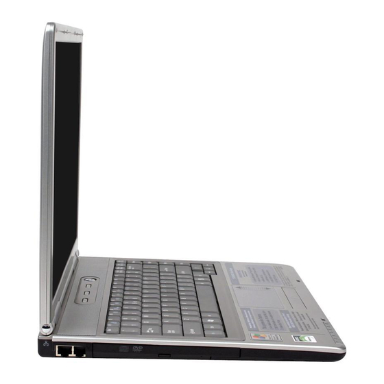
- Page 18 ¦ chapter 1 getting to know the basics Side Views Warning: Do not place any heavy objects on the top of notebook. This may damage the display 1. Ethernet / LAN Port The port connects to a network hub via the RJ-45 cable and also conforms to 10/100Base-TX transmission protocol.
- Page 19 ¦ chapter 1 getting to know the basics 4. PC Card Slot (Type II PCMCIA) and Card Eject Button The slot is where PC Card (Type II PCMCIA) is inserted. Press the eject button to release the PC Card. Note: For safety consideration, please insert the PCMCIA dummy card when not using the PCMCIA card.
- Page 20 ¦ chapter 1 getting to know the basics Bottom View 1. Battery Pack and Battery Latch The battery pack is a built-in power source for the notebook. Slide the battery latch to release the battery pack. 1-11...
- Page 21 ¦ chapter 1 getting to know the basics 2. Hard Disk Drive Cover The system’s hard disk drive is located under the cover. 3. System Device Cover The system’s processor with cooler assembly, Wireless LAN module, and DDR memory module are located under the case cover.
- Page 22 ¦ chapter 1 getting to know the basics AC Adapter DC-out Connector The DC-out connector docks to the power jack (DC-in) on the computer. 2. Adapter The adapter converts alternating current into constant DC voltage for the computer. 3. AC Plug The AC plug plugs to the AC wall outlet.
-
Page 23: Led Status Indicator
¦ chapter 1 getting to know the basics LED Status Indicator The LED Status Indicator displays the operating status of your notebook. When a certain function is enabled, an LED will light up. The following section describes its indication. System & Power Status Indicators LED Graphic Symbol Note:... -
Page 24: Keyboard Features
¦ chapter 1 getting to know the basics Keyboard Features Function Keys (Quick Keys) Graphic Symbol For various system controls, press the Fn (Function) key and the Fx key simultaneously. Action System Control Fn + F1 Enters Suspend Mode. Turns of the battery warning Fn + F3 beep off or on. - Page 25 ¦ chapter 1 getting to know the basics Windows Keys Your keyboard also has two Windows keys: 1. Start Key This key allows you to pull up the Windows Start Menu at the bottom of the taskbar. 2. Application Menu Key This key brings up the popup menu for the application, similar to a click of the right mouse button.
-
Page 26: Touch Pad
¦ chapter 1 getting to know the basics Touch Pad The built-in touch pad, which is a PS/2-compatible pointing device, senses movement on its surface. As you move your fingertip on the surface of the pad, the cursor responds accordingly. The following items teach you how to use the touch pad: 1. -
Page 27: Graphic Subsystem
¦ chapter 1 getting to know the basics Graphic Subsystem Your computer uses a high performance 15-inch active matrix TFT panel with high resolution and multi-million colors for comfortable viewing. The SiS Ultra256 video graphics accelerator, which is Microsoft DirectX 8. 1 compatible, performs graphic rendering at a lighting-fast speed. - Page 28 ¦ chapter 1 getting to know the basics Opening and Closing the Display Panel To open the display, push the LCD latch inwardly and lift up the lid. Then tilt it to a comfortable viewing position. To close the display cover, fold it down gently until the LCD latches click into place.
-
Page 29: Audio Subsystem
¦ chapter 1 getting to know the basics Audio Subsystem Your computer’s audio subsystem is Sound Blaster Pro-compatible. Adjusting the Volume Manually To increase the volume, press Fn+F5. To decrease the volume, press Fn+F6. Adjusting the Audio Volume in Windows 1. - Page 30 ¦ chapter 1 getting to know the basics Modem Your computer comes with a 56K V.92 internal fax/modem and a phone jack (RJ-11), which is located on the left side of your comput er. Use a telephone cable to connect the computer to the telephone wall outlet.
- Page 31 ¦ chapter 1 getting to know the basics Ethernet Your computer is equipped with a 10/100Base-TX Fast Ethernet network adapter. Connect the active LAN cable to the RJ-45 LAN port located on the left side of the computer. This allows you to access and transmit data in the local area network.
-
Page 32: Bios Setup And Security Feature
¦ chapter 2 bios setup and security feature BIOS SETUP AND SECURITY FEATURE In this chapter, you will learn how to enter the BIOS Setup Menu and manipulate various hardware control settings. You will also learn how to use the built-in security features. - Page 33 ¦ chapter 2 bios setup and security feature Setup Utility is a hardware configuration program built into your computer’s BIOS (Basic Input/Output System). It runs and maintains a variety of hardware functions. It is a menu-driven software, which allows you to easily configure and change the settings.
-
Page 34: Entering The Bios Setup Screen
¦ chapter 2 bios setup and security feature Entering the BIOS Setup Screen First turn on the power. When the BIOS performs the POST (Power-On Self Test), press F2 key quickly to activate the AMI BIOS Setup Utility. Note: You may need to press F2 key fairly quickly. Once the system begins to load Windows, you may have to retry by cycle-power on again Leaving the BIOS Setup Screen When you have finished modifying the BIOS settings, exit the BIOS. -
Page 35: Modifying The Bios Settings
¦ chapter 2 bios setup and security feature Modifying the BIOS Settings The AMIBIOS setup main menu is subdivided into sub-menus. Each menu item is described in this section. Main Setup Under this menu, you may change time/date and view basic processor and system memory information. -
Page 36: Boot Setup
¦ chapter 2 bios setup and security feature storage device. Selections / Item Sub-menu TouchPad Enabled Support Disabled Share 32MB Memory 64MB 128MB Enabled AutoDimm Disabled Function Boot Setup ? Boot Settings Configuration Selections / Item Sub-menu Quick Disabled Boot Enabled Quiet Boot Disabled Enabled... - Page 37 ¦ chapter 2 bios setup and security feature ? Boot Device Priority Selections / Item Sub-menu Removable Dev. 1st Boot Intel UNDI, PXE-2 Device Hard Drive CD/DVD 2nd Boot Device Note: If you select Intel UNDI, PXE -2, the system will attempt to boot from the network.
-
Page 38: Security Setup
¦ chapter 2 bios setup and security feature Security Setup ? Boot Settings Configuration Selections / Item Sub-menu Change Supervisor Password Change User Password Clear User Password Boot Disabled Sector Enabled Virus Protection Note: About Boot Sector Virus Protection: If enabled, the following warning message appears when a program attempts to alter the boot sector. - Page 39 ¦ chapter 2 bios setup and security feature The passwords activate two different levels of protection: 1. System always asks for password every time it is powered on. 2. System asks for password only when you attempt to enter BIOS utility. The passwords are encrypted and stored in NVRAM.
-
Page 40: Power Setup
¦ chapter 2 bios setup and security feature Power Setup Selections / Item Sub-menu Power Button On/Off Mode Suspend Note: The Suspend Mode selection in BIOS only applies to older Windows version (such as Windows 3.1 or Windows 95 or NT4) or non-Windows operating system. In Windows ME / 98SE / 2000 / XP, suspend mode and settings are determined by settings in the Power Options Properties (Start >... -
Page 41: Exit Setup
¦ chapter 2 bios setup and security feature Exit Setup Selections / Item Sub-menu Saves Changes and Exit Discard Changes and Exit Load Optimal Defaults 2-10 Description After you have completed the BIOS settings, select this item to save all settings, exit BIOS Setup utility, and reboot. - Page 42 ¦ chapter 3 battery power & power management C H A P T E R ? T H R E E BATTERY POWER & POWER MANAGEMENT In this chapter, you will learn the fundamentals of power management and how to use it to achieve longer battery life.
-
Page 43: The Battery Pack
¦ chapter 3 battery power & power management this chapter, you will learn how to operate your notebook on battery power, how to handle and maintain the battery pack, and learn about the system’s power saving features. TFT display, central processor, hard disk drive are the major hardware subsystems that consume the most power. -
Page 44: Battery Low-Power Warning
¦ chapter 3 battery power & power management Battery Low-Power Warning Low Battery Warning Low battery condition occurs when battery power is reduced to 6%. The red battery status LED indicator blinks and the system beeps once every 16 seconds or Very Low Battery Warning Very Low battery condition occurs at 3 % power remaining. -
Page 45: Installing And Removing The Battery Pack
¦ chapter 3 battery power & power management Installing and Removing the Battery Pack To Remove the Battery Pack: Place the notebook bottom-side up on a fl at and secured surface. Push the latch and pull the battery’s hard case away from the notebook. -
Page 46: To Install The Battery Pack
¦ chapter 3 battery power & power management To Install the Battery Pack: Place the notebook bottom-side up on a flat and secured surface. Carefully insert the battery pack into the battery compartment of the notebook. Charging the Battery and Charging Time To charge the battery, while the battery pack is in the notebook, plug the AC adapter into the notebook and an electrical outlet. -
Page 47: Checking The Battery Level
¦ chapter 3 battery power & power management Checking the Battery Level You can check the remaining battery power in the Windows battery status indicator, which is located at the lower right -hand corner of the task bar. (If you do not see a battery or AC-in icon on the task tray, go to Power Options Properties box and click on the Advanced tab. -
Page 48: Using Windows Power Options
¦ chapter 3 battery power & power management Using Windows Power Options Windows Power Management provides basic power saving features. In the Windows Power Options Properties [Start > Settings > Control Panel > Power Options] dialogue box, you may enter time-out values for display and hard disk drive. Windows power manager saves power by turning off hard drive after 1 minute of inactivity, for example. - Page 49 ¦ chapter 3 battery power & power management In this dialog box, you can manually set the LCD and hard drive’s time-out values in the Plugged in column and in the Running on batteries column. Lower time-out values will save more battery power. Note: Also consult Windows user guide for more information on how to use Windows power management functions.
-
Page 50: Suspend Mode
¦ chapter 3 battery power & power management Suspend Mode Standby Suspend The system automatically enters this mode after a period of inactivity, which is set in the Power Schemes dialog box. In Standby mode, hardware devices, such as display panel and hard disk, are turned off to conserve energy. - Page 51 ¦ chapter 3 battery power & power management Note: Do not install or remove the memory module when the system is in the suspend mode. Note: Actual dialogue box shown above may appear slightly different. 3-10...
-
Page 52: Power Button Action
¦ chapter 3 battery power & power management Power Button Action The notebook PC’s power button can be set to turn off the system or activate the suspend mode. Go to [Start > Settings > Control Panel > Power Options] and click on the Advanced tab. -
Page 53: Low Battery Warning
¦ chapter 3 battery power & power management Low Battery Warning You can define when and how the system warns you of its battery-low condition. Go to the Alarms tab in the Power Options Properties box. If you wish to hear audible beeps, click on the Alarm Action button and put a check on Sound Alarm. -
Page 54: Power Menu Quick Access
¦ chapter 3 battery power & power management Power Menu Quick Access Instead of making specific selections in the Power Options Properties box, you can quickly and easily specify which pre-set power saving function you desire by clicking on the Battery icon at the lower right-hand corner of the task bar. -
Page 55: Upgrading Your Computer
¦ chapter 4 upgrading your computer C H A P T E R ? F O U R UPGRADING YOUR COMPUTER In this chapter, you will learn how to upgrade the DRAM. -
Page 56: Upgrading The System Memory
¦ chapter 4 upgrading your computer Upgrading the System Memory Many applications will generally run faster when the computer’s dynamic memory capacity is increased. The computer provides two DDR memory sockets, located underneath the System Device Cover. You can increase the amount of memory by replacing the existing one with a dual inline memory module (commonly known as SO-DIMM) of a higher capacity. -
Page 57: Installing A Memory Module (Dimm) Into The System
¦ chapter 4 upgrading your computer Installing a memory module (DIMM) into the system To install the DIMM, do the following: Turn OFF the computer. Unhook the AC cord and all cables/devices attached to the notebook. Remove the battery pack. Place your hand on a large metal object momentarily to discharge any static electricity. - Page 58 ¦ chapter 4 upgrading your computer If you need to remove an old DIMM from the socket, press out on the latches located on both edges of the socket at the same time. The DIMM should pop up to an angle of 30 degree (see diagram below).
- Page 59 ¦ chapter 4 upgrading your computer Pivot the DIMM until the latches on both sides of the socket snap into place. Note: Notice the notch on the DIMM. The notches should fit nicely with the socket. Put the System Device Cover back and tighten 6 Screw C’s.
-
Page 60: Troubleshooting
¦ chapter 5 trouble shooting C H A P T E R ? F I V E TROUBLE SHOOTING In this chapter, you will learn how to solve common hardware and software problems. - Page 61 Your computer has been fully tested and complies with the system specifications before shipping. However, incorrect operations and/or mishandling may cause problems. This chapter provides a reference for identifying and correcting common hardware and software problems that you may encounter. When you encounter a problem, you should first try to go through the recommendations in this chapter.
- Page 62 ¦ chapter 5 trouble shooting hardware devices in the BIOS Setup utility. A faulty setting may cause the system to misbehave. If you are not sure of the changes you made, try to restore all the settings to factory defaults. Be sure all the device drivers are installed properly.
-
Page 63: Audio Problems
Audio Problems No speaker output - Turn up the volume dial located at the right edge of the computer. See Chapter 1 for its location. Software volume control is turned down in Microsoft Sound System or is muted. Double-click the speaker icon on the lower right corner of the taskbar to see if the speaker has been muted or turned down all the way. -
Page 64: Hard Disk Problems
Hard Disk Problems The hard disk drive does not work or is not recognizable - If you had just performed a hard disk upgrade, make sure the hard drive connector is not loose and the hard disk drive is also correctly seated. Remove it and reinsert it firmly, and restart your PC. - Page 65 for instructions on decreasing the cache size or on removing temporary Internet files. Empty the Recycle Bin to create more disk space. When you delete files, Windows saves them to the Recycle Bin. The hard disk takes longer to read a file - If you have been using the drive for a period, the files may be fragmented.
-
Page 66: Optical Drive Problems
Optical Drive Problems The optical drive does not work - Try rebooting the system. The disk is damaged or files are not readable. After you have inserted a CD-ROM disk, it may take a moment before you can access its content. The drive dose not read any disks - The CD may not be properly seated in the tray. -
Page 67: Display Problems
Display Problems The display panel is blank when the system is turned on - Make sure the computer is not in the Standby or Hibernate suspend modes. The display is turned off to conserve energy in these modes. The screen is difficult to read - The display resolution should at least be set to at least1024x768 for optimal viewing. -
Page 68: Keyboard And Mouse Problems
Keyboard and Mouse Problems The built-in touch pad performs erratically - Make sure there is no excess perspiration or humidity on your hand when using the touch pad. Keep the surface of the touch pad clean and dry. Do not rest your palm or wrist on the surface of the touch pad while typing or using the touch pad. -
Page 69: Cmos Battery Problem
CMOS Battery Problem A message “CMOS Checksum Failure” displays during the booting process or the time (clock) resets when booting - Try to reboot the system. If the message “CMOS Checksum Failure” appears during the booting procedure even after rebooting, it may indicate failure of the CMOS battery. -
Page 70: Memory Problems
Memory Problems The POST does not show an increased memory capacity when you have already installed additional memory - Certain brands of memory module may not be compatible with your system. You should ask your vendor for a list of compatible DIMM. The memory module may not be installed properly. -
Page 71: Modem Problems
Modem Problems The built-in modem does not respond - Make sure the modem driver is loaded properly. Go to [Start > Settings > Control Panel > Phone and Modem Options] and go to Modems tab. Make sure a 56K Voice Modem is listed. Otherwise, click the Add button to add the modem drive, which is located in the factory CD-ROM (or floppy diskette). -
Page 72: Network Adapter / Ethernet Problems
Network Adapter / Ethernet Problems The Ethernet adapter does not work - Go to [Start > Settings > Control Panel > System > Hardware > Device Manager]. Double-click on Network Adapters and check if Ethernet NIC appears as one of the adapters. -
Page 73: Pc Card (Pcmcia) Problems
PC Card / PCMCIA Problems Note: Some system may not have the PC Card Slot option. PC Cards do not function- Make sure you have properly installed the driver for the card. Consult the card’s manual or contact the vendor for trouble-shooting. -
Page 74: Performance Problems
Performance Problems The computer becomes hot - In a 35 computer’s back case are expected to reach 50 degrees. Make sure the air vents are not blocked. If the fan does not seem to be working at high temperature (50 degrees Celsius and up), contact the service center. -
Page 75: Firewire (Ieee1394) And Usb2.0 Problems
FireWire (IEEE1394) and USB2.0 Problems The USB device does not work - Check the settings in the Windows Control Panel. Make sure you have installed the necessary device drivers. Contact the device vendor for additional support. The IEEE1394 port does not work - Go to [Start >... -
Page 76: Product Specification
¦ appendix A product specification PRODUCT SPECIFICATION... -
Page 77: System Memory
¦ appendix A product specification n Processor n Memory Type DDR SDRAM 333 (PC2700 compatible) 256 / 512MB, 2.5-Volt, 64-bit bus n Default Two 200-pin DIMM sockets, Max 1 GB n Memory Expansion n LCD Panel n Graphic Integrated Ultra256 2D / 3D graphics accelerator Accelerator 4X AGP architecture graphics capability n AGP Bus... -
Page 78: Wireless Lan
¦ appendix A product specification n Audio Codec Integrated audio controller n Sound DirectSound 3D, EAX 1.0 & 2.0 compatible Capabilities A3D, I3DL2 compatible AC97 V2. 2 compatible 2 Stereo Speakers n Transmission Integrated Modem Controller with MDC card, AC97 Rate V2.2 Modem support V.92 / V.90 / K56flex for download data speed up to... -
Page 79: Keyboard & Touch Pad
¦ appendix A product specification n Capabilities IEEE1394 OHCI Host Controller and Up to 400 Mbps Expandable up to 63 devices in chains n Hard Drive 2.5-inch format hard disk drive n Combo Drive 5.25-inch format (12.7mm height) fixed module n Keyboard 86-key QWERTY keyboard with embedded numeric keypad and Windows keys, 19.05mm Pitch... -
Page 80: Ports And Connectors
¦ appendix A product specification n Mic-In Port One Microphone-in jack n Audio-Out / SPDIF One Headphone / SPDIF jack n Audio-in Port One Line-in jack n FireWire One FireWire (IEEE1394) host connector n USB2.0 Port Three USB2.0-compliant connectors n Ethernet One standard network Ethernet connector (RJ-45) n Modem One modem / phone connector (RJ11) -
Page 81: Physical Specification
¦ appendix A product specification n PnP Function AMI PnP BIOS n Self Test Power On Self Test n Auto DRAM auto-detection, auto-sizing Detection L2 Cache auto-detection Hard disk type auto-detection n Power APM 1.2 (Advanced Power Management) & Management ACPI 2.0 (Advanced Configuration Power Interface) n Security Two Level Password Protections... -
Page 82: Agency Regulatory Notices
¦ appendix B agency regulatory notices AGENCY REGULATORY NOTICES... - Page 83 ¦ appendix B agency regulatory notices Federal Communications Commission Notice This equipment has been tested and found to comply with the limits for a Class B digital device, pursuant to Part 15 of the FCC Rules. These limits are designed to provide reasonable protection against harmful interference in a residential installation.
- Page 84 ¦ appendix B agency regulatory notices The transmitter module may not be co-located with any other transmitter or antenna. As long as conduction above is met, further transmitter test will not be required. However, the OEM integrator is still responsible for testing their end-product for any additional compliance requirements required with this module installed (for Notebook).
- Page 85 ¦ appendix B agency regulatory notices Declaration of Conformity This device complies with Part 15( CLASS B)/68 the FCC Rules. Operation is subject to the following two conditions: (1) this device may not cause harmful interference, and (2) this device must accept any interference received, including interference that may cause undesired operation.
- Page 86 ¦ appendix B agency regulatory notices Power Cord Requirement The power cord supplied with the AC adapter should match the plug and voltage requirements for your local area. Regulatory approval for the AC adapter has been obtained using the power cord for the local area. However, if you travel to a different area and need to connect to a different outlet or voltage, you should use one of the power cords listed below.
- Page 87 ¦ appendix B agency regulatory notices CCC (China) PSB (Singapore) PSE (Japan) BSMI (Taiwan) B (Polish) VDE (Germany) SASO (Saudi Arabia) The flexible cord must be of a HAR (harmonized) type HO5VV-F 3-conductor cord with a minimum conductor size of 0.03 square inches.
- Page 88 ¦ appendix B agency regulatory notices and seek medical attention. Do not charge the battery pack if the ambient temperature exceeds 45? (113? ). To obtain a replacement battery, contact your local dealer. Do not expose the battery pack to high storage temperatures (above 60? , 140? ).
- Page 89 ¦ appendix B agency regulatory notices instruments, such as magnifying lenses, with this product increase the potential hazard to your eyes. For your safety, have this equipment serviced only by an authorized service provider. Lithium battery warning / Bridge battery warning This computer contains a lithium battery to power the clock and calendar circuitry.
Need help?
Do you have a question about the AV5500 and is the answer not in the manual?
Questions and answers