Table of Contents
Advertisement
Available languages
Available languages
Advertisement
Chapters
Table of Contents

Related Manuals for Homewerks SmartVent 7146-80-MS


Summary of Contents for Homewerks SmartVent 7146-80-MS
- Page 1 SmartVent BATHROOM VENTILATION FAN MODEL 7146-80-MS Español p. 13 Questions, problems, missing parts? Before returning to the store, call our customer service department at 1-877-319-3757, 7:30 a.m. - 4:30 p.m., CST, Monday - Friday. READ AND SAVE THESE INSTRUCTIONS 04-28-2020 HomewerksWW.com...
-
Page 2: Table Of Contents
TABLE OF CONTENTS Product Specifications ........................2 UL Compliance ..........................2 FCC Compliance ..........................2 Package Contents ........................... 3 Hardware Included .......................... 3 Safety Information ........................... 4 Preparation ............................4 New Construction Installation Instructions ..................6 Existing Construction Installation Instructions .................. 8 LED Wall Switch Operation ...................... -
Page 3: Package Contents
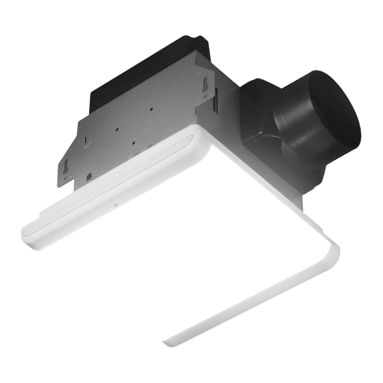
PACKAGE CONTENTS PART DESCRIPTION PART DESCRIPTION Fan Housing LED Touchpad Wall Switch Grille with LED Lights HARDWARE INCLUDED (not actual size) Wood Screw M4 x 30 Qty. 4 HomewerksWW.com... -
Page 4: Safety Information
SAFETY INFORMATION Please read and understand this entire manual before attem ting to assemble, operate or install the product. • Always disconnect the power supply prior to servicing WARNING: To reduce the risk of fire, electric the fan, motor or junction box. shock, or injury to persons, observe the following: •... - Page 5 PREPARATION (continued) WARNING: RISK OF ELECTRIC SHOCK! Ensure the electricity to the wires you are working on is shut off. Either remove the fuse or turn off the circuit breaker before removing the existing bath fan or installing the new one. Before removing your current ventilation fan, verify the wall switch box has the required wires necessary for this installation.
-
Page 6: New Construction Installation Instructions
NEW CONSTRUCTION INSTALLATION INSTRUCTIONS BEFORE INSTALLATION WARNING: RISK OF ELECTRIC SHOCK! Ensure the electricity to the wires you are working on is shut off. Either remove the fuse or turn off the circuit breaker before removing the existing bath fan or installing the new one. - Page 7 NEW CONSTRUCTION INSTALLATION INSTRUCTIONS (continued) 5. Remove the wiring box cover from the fan housing (A). Pull the house wires through the hole in the wiring box cover. Using the quick connectors, connect the house wiring from the wall switch to the fan housing (A).
-
Page 8: Existing Construction Installation Instructions
EXISTING CONSTRUCTION INSTALLATION INSTRUCTIONS BEFORE INSTALLATION WARNING: RISK OF ELECTRIC SHOCK! Ensure the electricity to the wires you are working on is shut off. Either remove the fuse or turn off the circuit breaker before removing the existing bath fan or installing the new one. - Page 9 EXISTING CONSTRUCTION INSTALLATION INSTRUCTIONS (continued) 5. With the screws removed, slide the grille mounting brackets to the side and remove them from the fan housing (A). Unplug the three prong fan plug and pull the black fan motor out of the fan housing (A). Mounting brackets plug...
- Page 10 EXISTING CONSTRUCTION INSTALLATION INSTRUCTIONS (continued) 9. Plug the three prong plug on the fan motor back into the fan housing (A). Place the fan motor back into the fan housing (A), aligning the duct with the duct opening in the fan housing (A). Replace the grille mounting brackets and secure with the screws removed earlier.
-
Page 11: Led Wall Switch Operation
LED WALL SWITCH OPERATION 1. LED Light: Press for ON/OFF. 2. Dimmer: Press multiple times to adjust brightness. 3. Night Light: Press for ON/OFF 4. Humidity Sensor: Press for ON/OFF. 5. Fan: Press for ON/OFF 6. Motion Sensor: Press for ON/OFF 7. -
Page 12: Troubleshooting
CARE AND CLEANING 4. Attach grille (B) by pinching the mounting springs and inserting them into the narrow rectangular slots in the fan housing (A). Housing slots Turn on power source. Test the unit. Mounting spring Mounting spring TROUBLESHOOTING PROBLEM POSSIBLE CAUSE SOLUTION The fan seems louder than it... - Page 13 VENTILADOR DE BAÑO SmartVent MODELO 7146-80-MS ¿Tiene preguntas, problemas, o faltan piezas? Antes de regresar a la tienda, llame al Servicio al Cliente, 1-877-319-3757, de lunes a viernes, de 7:30 a.m. a 4:30 p.m., hora estándar central. CONSERVE ESTE MANUAL PARA USO FUTURO HomewerksWW.com...
-
Page 14: Especificaciones Del Producto
TABLE DE CONTENIDO Especificaciones del Producto ....................... 14 Cumplimiento UL ........................... 14 Cumplimiento de la Normas FCC ....................14 Contenido del Paquete ........................15 Materiales Incluidos ........................15 Información sobre Seguridad ......................16 Preparación ........................... 18 Instrucciones de Installación - Nueva Construcción ............... 18 Instrucciones de Installación - Construcción Existente .............. -
Page 15: Contenido Del Paquete
CONTENIDO DEL PAQUETE PARTE DESCRIPCIÓN CANT. PARTE DESCRIPCIÓN CANT. Cuerpo del ventilador Interruptor de pared con panel táctil LED Rejilla con luces LED MATERIALES INCLUIDOS (Los materiales no se ilustran en tamaño real) Tornillo Para Madera M4 x 30mm Cant. 4 HomewerksWW.com... -
Page 16: Información Sobre Seguridad
INFORMACIÓN SOBRE SEGURIDAD Por favor, lea y comprenda este manual en su totalidad antes de intentar de ensamblar, operar o instalar el producto. • Siempre desconecte la fuente de alimentación antes de ADVERTENCIA: Para reducir el riesgo de darle servicio al ventilador, motor o caja eléctrica. incendio, choque eléctrico o lesiones a las personas, respete lo siguiente: •... - Page 17 PREPARACIÓN (continuada) ADVERTENCIA: ¡RIESGO DE DESCARGA ELECTRIC! Asegurese de cortar el suministro eléctrico en los cables con los que trabajara. Extraiga los fusibles o apague el cortacircuitos antes de quitar el ventilador de baño existente o instalar uno nuevo. Antes de quitar su ventilador actual, verifique que su caja de interruptores en la pared tenga los cables de suministro necesarios para esta instalación.
-
Page 18: Instrucciones De Installación - Nueva Construcción
INSTRUCCIONES DE INSTALACIÓN - NUEVA CONSTRUCCIÓN PREVIO A LA INSTALACIÓN ADVERTENCIA: ¡RIESGO DE DESCARGA ELECTRICA! Asegurese de cortar el suministro electrico en los cables con los que trabajara. Extraiga los fusibles o apague el cor- tacircuitos antes de quitar el ventilador de baño existente o instalar uno nuevo. - Page 19 INSTRUCCIONES DE INSTALACIÓN - NUEVA CONSTRUCCIÓN (continuada) 5. Retire la cubierta de la caja de cableado de la caja del ventilador (A). Jale los cables de la casa a través del orificio en la cubierta de la caja de cableado. Usando los conectores rápidos, conecte el cableado de la casa desde el interruptor de pared a la caja Cubierta de la del ventilador (A).
-
Page 20: Instrucciones De Installación - Construcción Existente
INSTRUCCIONES DE INSTALLACIÓN - CONSTRUCCIÓN EXISTENTE PREVIO A LA INSTALACIÓN ADVERTENCIA: ¡RIESGO DE DESCARGA ELECTRICA! Asegurese de cortar el suministro electrico en los cables con los que trabajara. Extraiga los fusibles o apague el cortacircuitos antes de quitar el ventilador de baño existente o instalar uno nuevo. - Page 21 INSTRUCCIONES DE INSTALLACIÓN - CONSTRUCCIÓN EXISTENTE (continuada) 5. Con los tornillos quitados, deslice los soportes de montaje de la rejilla hacia un lado y retírelos de la caja del ventilador (A). Desenchufe el enchufe de tres puntas del ventilador y saque el motor negro del ventilador de la caja del ventilador (A).
- Page 22 INSTRUCCIONES DE INSTALLACIÓN - CONSTRUCCIÓN EXISTENTE (continuada) 9. Vuelva a enchufar el enchufe de tres puntas del motor del ventilador a la caja del ventilador (A). Vuelva a colocar el motor del ventilador en la caja del ventilador (A), alineando el conducto con la abertura del conducto en la caja del ventilador (A).
-
Page 23: Cuidado Y Limpieza
OPERACIÓN DEL INTERRUPTOR DE PARED LED 1. Luz LED: Presione para encender / apagar. 2. Atenuador: Presione varias veces para ajustar el brillo. 3. Luz nocturna: Presione para activar / desactivar. 4. Sensor de humedad: Presione para activar / desactivar. 5. -
Page 24: Solución De Problemas
CUIDADO Y LIMPIEZA (continuada) 4. Fije la rejilla (B) apretando los resortes de montaje e insertán- Ranuras dolos en las ranuras rectangulares estrechas en la caja del ventilador (A). en la caja Encienda la fuente de energía. Resortes de montaje Resortes de montaje SOLUCIÓN DE PROBLEMAS...
Need help?
Do you have a question about the SmartVent 7146-80-MS and is the answer not in the manual?
Questions and answers
How do I adjust the light setting to brighten the light
To adjust the light setting on the Homewerks 7146-80-MS to brighten the light, press the Light button to cycle through the 4 available brightness levels until the desired brightness is reached.
This answer is automatically generated
Is there a way to adjust the amount of time that the light stays on with the motion sensor activated? Model 7146-80-MS. THANK YOU.