Table of Contents
Advertisement
Available languages
Available languages
Quick Links
ATTACH YOUR RECEIPT HERE
Serial Number _______________ Purchase Date ______________
Questions, problems, missing parts? Before returning to your retailer, call our customer
service department at 1-877-319-3757, 7:30 a.m. - 4:30 p.m., CST, Monday - Friday.
READ AND SAVE THESE INSTRUCTIONS
VENTILATION
FAN WITH LIGHT
MODELS #7117-01-WH, #7117-01-BN
Español p. 11
04-24-19
Advertisement
Chapters
Table of Contents

Related Manuals for Homewerks 7117-01-BN


Summary of Contents for Homewerks 7117-01-BN
- Page 1 VENTILATION FAN WITH LIGHT MODELS #7117-01-WH, #7117-01-BN Español p. 11 ATTACH YOUR RECEIPT HERE Serial Number _______________ Purchase Date ______________ Questions, problems, missing parts? Before returning to your retailer, call our customer service department at 1-877-319-3757, 7:30 a.m. - 4:30 p.m., CST, Monday - Friday.
-
Page 2: Table Of Contents
TABLE OF CONTENTS Specifications .............................2 Package Contents ..........................3 Safety Information ..........................3 Preparation ............................4 Dimension Requirements ........................5 New Construction Assembly Instructions ...................5 Existing Construction Assembly Instructions ..................7 Care and Maintenance ........................10 Troubleshooting ..........................10 Warranty ............................10 SPECIFICATIONS PRODUCT SPECIFICATIONS LIGHT SPECIFICATIONS Airflow: 80 CFM 3000K Dimmable LED Sound output: 1.1 Sones 80 CRI... -
Page 3: Package Contents
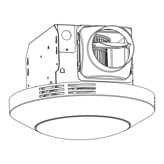
PACKAGE CONTENTS PART DESCRIPTION QUANTITY PART DESCRIPTION QUANTITY Fan housing Duct connector Grille and light HARDWARE CONTENTS (not shown actual size) Long Wood Screw Qty. 6 SAFETY INFORMATION READ AND SAVE THESE INSTRUCTIONS Please read and understand this entire manual before attempting to assemble, operate or install the product. -
Page 4: Preparation
SAFETY INFORMATION Sufficient air supply is required for proper combustion and the exhaustion of gases through the chimney (flue) of fuel burning equipment to prevent back-drafting. See the standards of NFPA (National Fire Protection Association) and ASHRAE (American Society for Heating Refrigeration and Air Conditioning Engineers) and the local building code authorities. -
Page 5: Dimension Requirements
DIMENSION REQUIREMENTS Ceiling Ceiling Ceiling QUICK CONNECTOR INSTRUCTIONS Opening (L) Opening (W) Opening (H) To be sold only with installation instructions. WARNING: Wiring must comply with all appliable electrical 7-1/2 in. 7-1/4 in. 5-3/4 in. codes. Turn OFF power before removing or installing connectors. WARNING: COPPER TO COPPER ONLY. - Page 6 NEW CONSTRUCTION INSTALLATION INSTRUCTIONS Place the fan housing next to a ceiling joist. The fan housing should be level and perpendicular to the joist. Mount the fan housing to the ceiling joist using the Ceiling joist wood screws (included) where indicated. Remove wiring box cover from fan housing with Phillips screwdriver (not included).
-
Page 7: Existing Construction Assembly Instructions
NEW CONSTRUCTION INSTALLATION INSTRUCTIONS Install a circular 4 in. duct (not included) and secure Fan housing it with duct tape or clamps (neither included). Finish 4 in.duct ceiling work. Ceiling hole should be aligned with edge of fan housing. Ceiling Duct tape or clamp Attach LED wire connections to the inserts in the fan... - Page 8 EXISTING CONSTRUCTION INSTALLATION INSTRUCTIONS Unplug the fan power unit. Remove three screws on the side of the fan housing that hole the fan motor housing assembly in place. Remove the fan motor assembly from the fan housing. Remove wiring box cover from fan housing with a Phillips screwdriver (not included).
- Page 9 EXISTING CONSTRUCTION ASSEMBLY INSTRUCTIONS Insert fan housing through existing hole in ceiling. The fan housing should be level and perpendicular to the joist. Mount fan housing to the joist by screwing in three screws (included) through the three holes located on Ceiling joist the inside of the fan housing.
-
Page 10: Care And Maintenance
CARE AND MAINTENANCE WARNING: Disconnect power supply before servicing. See SAFETY INFORMATION before proceeding. Routine mainte- nance should be done at least once a year. • Wash grille with mild soap and water, dry with a cloth. • Remove excess dirt and dust from the fan housing with a vacuum cleaner. •... - Page 11 VENTILACIÓN VENTILADOR CON LUZ MODELOS #7117-01-WH, #7117-01-BN ¿Preguntas, problemas, piezas faltantes? Antes de volver a su distribuidor, llame a nuestro departamento de servicio al cliente al 1-877-319-3757, de 7:30 a.m. a 4:30 p.m., CST, de lunes a viernes. LEA Y GUARDE ESTAS INSTRUCCIONES...
-
Page 12: Especificaciones
TABLA DE CONTENIDO Especificaciones ..........................12 Contenido del paquete ........................13 Información de seguridad .........................14 Preparación ............................14 Requisitos de dimensión ........................15 Instrucciones de montaje de nueva construcción................15 Instrucciones de montaje de construcción existentes ..............17 Cuidado y mantenimiento .........................20 Solución de problemas ........................20 Garantía............................20 ESPECIFICACIONES ESPECIFICACIONES DEL PRODUCTO... -
Page 13: Contenido Del Paquete
CONTENIDOS DEL PAQUETE PARTE DESCRIPCIÓN CANTIDAD PARTE DESCRIPCIÓN CANTIDAD Carcasa del ventilador Conector de conducto Parrilla y luz CONTENIDO DE HARDWARE (no se muestra el tamaño real) Madera larga Tornillo Cant. 6 INFORMACIÓN DE SEGURIDAD LEA Y GUARDE ESTAS INSTRUCCIONES Lea y comprenda todo este manual antes de intentar ensamblar, operar o instalar el producto. -
Page 14: Información De Seguridad
INFORMACIÓN DE SEGURIDAD Se requiere suficiente suministro de aire para una combustión adecuada y el agotamiento de los gases a través de la chimenea (chimenea) de los equipos que queman combustible para evi- tar el retroceso. Ver los estándares de NFPA (National Fire Protection Association) y ASHRAE (American Society for Heating Ingenieros de refrigeración y aire acondicionado) y las autoridades locales de códigos de construcción. -
Page 15: Requisitos De Dimensión
REQUISITOS DE DIMENSION Abertura del Abertura del Abertura del techo (L) techo (W) techo (H) 7-1/2 in. 7-1/4 in. 5-3/4 in. DIAGRAMA DE CABLEADO Caja de interruptores Ventilador Apagado Negro Vivir Blanco Neutral Verde Suelo INSTRUCCIONES DE INSTALACIÓN DE NUEVA CONSTRUCCIÓN Revise todas las precauciones de seguridad. - Page 16 INSTRUCCIONES DE INSTALACIÓN DE NUEVA CONSTRUCCIÓN Retire la cubierta de la caja de cableado de la caja del venti- lador con destornillador Phillips (no incluido). Coloque el alojamiento del ventilador junto a una vigueta de techo o perno de la pared. La carcasa del ventilador debe estar nivelada y perpendicular a la vigueta o espárrago.
-
Page 17: Instrucciones De Montaje De Construcción Existentes
INSTRUCCIONES DE INSTALACIÓN DE NUEVA CONSTRUCCIÓN Instale un conducto circular de 4 pulg. (No incluido) y asegúrelo con cinta adhesiva o abrazaderas (no incluidas). Terminar el trabajo de techo. El orificio del techo debe estar Caja del ventilador 4 pulg.conducto alineado con el borde de la caja del ventilador. - Page 18 INSTRUCCIONES DE INSTALACIÓN DE CONSTRUCCIÓN EXISTENTES Retire la cubierta de la caja de cableado de la caja del ventilador con un destornillador Phillips (no incluido). Tire de los cables de la casa a través del orificio de la cubierta de la caja de cables (6A). Con un conector rápido, Cables Conexión rápida...
- Page 19 INSTRUCCIONES DE INSTALACIÓN DE CONSTRUCCIÓN EXISTENTES Inserte la carcasa del ventilador a través del orificio existente en el techo. La carcasa del ventilador debe estar nivelada y perpendicular.a la vigueta. Monte la carcasa del ventilador en la vigueta atornillando los tres tornillos (incluidos) a través de los tres orificios Vigueta de techo ubicados en el interior de la carcasa del ventilador.
-
Page 20: Cuidado Y Mantenimiento
CUIDADO Y MANTENIMIENTO ADVERTENCIA: Desconecte la fuente de alimentación antes de realizar el mantenimiento. Consulte la INFORMACIÓN DE SEGURIDAD antes de continuar. El mantenimiento de rutina debe hacerse al menos una vez al año. • Lave la rejilla con un jabón suave y agua, seque con un paño. •...
Need help?
Do you have a question about the 7117-01-BN and is the answer not in the manual?
Questions and answers