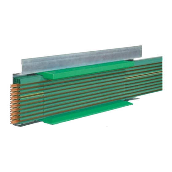
Vahle VKS 10 Mounting Instructions - Maintenance
Hide thumbs
Also See for VKS 10:
- Translation of the original instructions (99 pages) ,
- Mounting instructions - maintenance (24 pages)
Table of Contents
Advertisement
Quick Links
Advertisement
Table of Contents

Subscribe to Our Youtube Channel
Summary of Contents for Vahle VKS 10
- Page 1 Montageanleitung - Wartung VKS 10 Mounting Instructions - Maintenance VKS 10...
-
Page 2: Table Of Contents
Montageanleitung Mounting instructions Mounting instructions VKS 10 Sicherheitshinweise ... .3 Safety Instructions ....3 Halteeisen anbringen ...4 Mounting of support brackets . -
Page 3: Sicherheitshinweise
Montageanleitung Mounting instructions V V K K S S 1 1 0 0 Sicherheitshinweise Safety Instructions Warnhinweise und Symbole Warnings and Symbols Folgende Benennungen und Zeichen The following denominations and sym- werden in dieser Anleitung für besonders bols are used in this manual for particu- wichtige Angaben benutzt: larly important indications: Verletzungsgefahr durch... -
Page 4: Halteeisen Anbringen
VKS hangers. Support Ausführung erfolgt kundenseitig. Der brackets are usually installed by the cus- Einsatz von Sonderkonstruktionen ist tomer. VAHLE can suggest and design möglich. special support arrangements. Bringen Sie die Halteeisen parallel Install the support brackets parallel and und rechtwinklig zur Fahrschiene an. -
Page 5: Schleifleitung Aufhängen Und Verbindungsstoß Einstellen
Montageanleitung Mounting instructions VKS 10 Setzen die die erste VKS-Auf- Place the first support at a hängung max. 300 mm vom distance of max. 200 mm from Teilstückende. the end the conductor rail section. Schleifleitung aufhängen und Installation of the VKS conductor Verbindungsstoß... - Page 6 Tabelle Zuordnung Steckverbinder 10-100 A (Kupfer) 120-140 A (Kupfer) Table allocation plug-in joints 10-100 A (copper) 120-140 A (copper) VKS 10- 6/ 60 – L1; L2; L3; PE; 1;2 VKS 10- 6/100 L1; L2; L3; PE; 1;2 – VKS 10- 6/120 PE;...
- Page 7 Montageanleitung Mounting instructions V V K K S S 1 1 0 0 Setzen Sie nun das nächste Teilstück Now place the adjoining section from ebenfalls von vorne in die Aufhän- the front into the hanger and lock it in gung und rasten es ein.
-
Page 8: Unterlängen
Montageanleitung Mounting instructions VKS 10 Unterlängen Short-lengths Wir fertigen die Unterlängen nach Ihren An- We manufacture short-lengths according gaben im Werk. Falls Unterlängen auf der to customer`s specifications in our factory. Baustelle noch angepasst werden müssen, If short-lengths still need to be adapted bearbeiten Sie die Schleifleitung wie folgt. -
Page 9: Einspeisungen
Montageanleitung Mounting instructions VKS 10 Einspeisungen Feed terminals max. 300 mm Streckeneinspeisungen Mount line feeds preferably on sind vorzugsweise auf einem a 1 m section. 1 m Schleifleitungsstück mon- tiert. Setzen Sie die Einspeisung möglichst If at all possible, place the feed termi- in die Nähe der Zuleitung. -
Page 10: Kopfeinspeisung Veks 10
Montageanleitung Mounting instructions VKS 10 Anzugsmomente in Anlehnung Torque accordance an die DIN VDE 0220 T2 DIN VDE 0220 T2 M 10 = 44 Nm M 10 = 44 Nm M 5 = 5 Nm. M 5 = 5 Nm. -
Page 11: Stromanschluss Herstellen
Montageanleitung Mounting instructions VKS 10 Die Einbauhöhe „H“ (S1) ent- The installation height "H" (S1) nehmen Sie bitte der Tabelle T3. of the current collectors, is shown in table T3. Schieben Sie den Stromabnehmer in Push the current collector into die vorgesehene Position. -
Page 12: Einführungstrichter
Montageanleitung Mounting instructions VKS 10 Schliessen Sie die Einspeisung an das Connect the feed terminal to the main Stromnetz an (siehe Kapitel Einspeisungen). power supply (see chapter on feed termi- nals). Verdrahten Sie die Stromabnehmer Wire the current collectors to the mit den Verbrauchern. -
Page 13: Schienentrennungen
Montageanleitung Mounting instructions VKS 10 Schienentrennungen Conductor isolators Mit den Schienentrennungen wird die The conductors may be electrically sepa- Schleifleitung elektrisch getrennt. Der Ein- rated by installing isolators. The isolators bau im VKS-Teilstück erfolgt werkseitig. are installed at the factory. - Page 14 Montageanleitung Mounting instructions VKS 10 Stromabnehmer Die Stromabnehmer müssen alle 2 Mo- nate bzw. nach betrieblichen Erfordernis- Current collector sen kontrolliert werden. The current collectors must be checked every two months or in accordance with a) Mechanische Kontrolle: operational requirements.
-
Page 15: Notizen
Montageanleitung Mounting instructions VKS 10 Notizen: Notices:... - Page 16 PVC Enclosed Conductor System MKLD - MKLF - MKLS ... .4 c Sicherheits-Schleifleitungen Kunststoff VKS 10 PVC Enclosed Conductor Systems VKS 10 ......4 d Sicherheits-Schleifleitungen Kunststoff KBH PVC Enclosed Conductor Systems KBH .


Need help?
Do you have a question about the VKS 10 and is the answer not in the manual?
Questions and answers