Vahle VKS 10 Mounting Instructions - Maintenance
Hide thumbs
Also See for VKS 10:
- Translation of the original instructions (99 pages) ,
- Mounting instructions - maintenance (16 pages)
Table of Contents
Advertisement
Quick Links
Advertisement
Table of Contents

Related Manuals for Vahle VKS 10


Summary of Contents for Vahle VKS 10
- Page 1 Montageanleitung - Wartung VKS 10 Mounting Instructions - Maintenance VKS 10...
-
Page 2: Table Of Contents
• Montageanleitung Mounting instructions VKS 10 Inhaltsverzeichnis Table of content 1 Hinweise zur Dokumentation 1 Information on the Documentation 1.1 Mitgeltende Unterlagen 1.1 Additional documents 1.2 Verwendete Symbole 1.2 Symbols used 2 Sicherheitshinweise 2 Safety instructions 2.1 Qualifikation des Personals 2.1 Personnel qualifications... -
Page 3: Hinweise Zur Dokumentation
• Montageanleitung Mounting instructions VKS 10 1 Hinweise zur Dokumentation 1 Information on the Documentation 1.1 Mitgeltende Unterlagen 1.1 Additional documents Diese Montageanleitung sowie alle mitgel- These mounting instructions and all addi- tenden Unterlagen sind Teil des Produktes. tionally applicable documents are part of Sie müssen dem Anlagenbetreiber ausge-... -
Page 4: Sicherheitshinweise
• Montageanleitung Mounting instructions VKS 10 2 Sicherheitshinweise 2 Safety instructions 2.1 Qualifikation des Personals 2.1 Personnel qualifications Montage, Installation Wartung Assembly, installation and maintenance dürfen nur durch ausgebildetes Fachper- work may only be carried out by trained sonal erfolgen. -
Page 5: Allgemeines
• Montageanleitung Mounting instructions VKS 10 4 Allgemeines 4 General Gefahr durch Quetschen Risk of pinching between zwischen bewegten und mobile and fixed festen Teilen! components! Es muss sichergestellt werden, You must ensure that the dass durch die Anordnung von... -
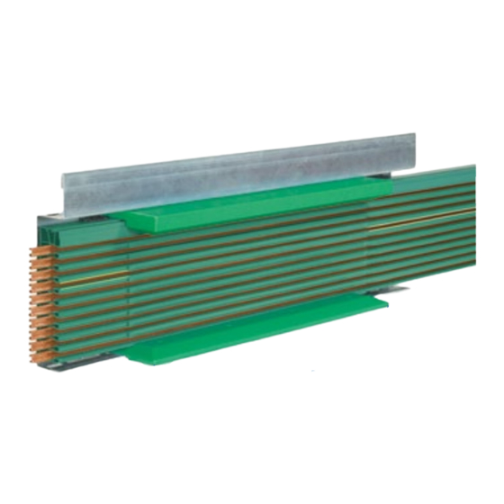
Page 6: Schleifleitungen Montieren
VKS hangers. Support Ausführung erfolgt kundenseitig. Der brackets are usually installed by the cus- Einsatz von Sonderkonstruktionen ist tomer. VAHLE can suggest and design möglich. special support arrangements. Bringen Sie die Halteeisen parallel Install the support brackets parallel and und rechtwinklig zur Fahrschiene an. -
Page 7: Schleifleitung Aufhängen Und
• Montageanleitung Mounting instructions VKS 10 5.3 Schleifleitung aufhängen 5.3 Installation of the VKS conductor rail Verbindungsstoß einstellen and splice joint adjustment Verlegen Sie die Schleifleitung gerade Install the conductor rail straight and und parallel zur Kranbahn. parallel to the machinery track. - Page 8 L1; L2; L3 – VKS 10- 9/140 PE; 1; 2; 3; 4; 5 – L1; L2; L3 VKS 10- 9/200 (1) -240 1; 2 2 x L1; 2 x L2; 2 x L3; PE – VKS 10- 9/280 (1) 1; 2;...
- Page 9 • Montageanleitung Mounting instructions VKS 10 Setzen Sie nun das nächste Teilstück Now place the adjoining section from ebenfalls von vorne in die Aufhän- the front into the hanger and lock it in gung und rasten es ein. there. Schieben Sie die beiden Teilstücke zu- Push the two conductor sections to- sammen, bis die Steckverbinder einfä-...
-
Page 10: Unterlängen
• Montageanleitung Mounting instructions VKS 10 Die Einstellmaße nach Tabelle adjustment dimensions T2 müssen nur dann genau according to Table T2 must only eingehalten werden, wenn der be observed precisely if the max. für die Schleifleitung max. temperature range (-10 °C to + Temperaturbereich (-10 °C bis... -
Page 11: Biegen Der Schleifleitung
• Montageanleitung Mounting instructions VKS 10 Schieben Sie nun die Stromschiene Now push back the copper conduc- soweit zurück, bis beidseitig der glei- tor until it extends equally on both che Überstand ,,B“ erreicht ist (G11). sides of the PVC housing ,,B’’ (G11). -
Page 12: Einspeisungen
• Montageanleitung Mounting instructions VKS 10 6 Einspeisungen 6 Feed terminals Die Streckeneinspeisungen sind Mount line feeds preferably on vorzugsweise auf einem 1 m a 1 m section. Schleifleitungsstück montiert. Setzen Sie die Einspeisung möglichst If at all possible, place the feed termi- in die Nähe der Zuleitung. -
Page 13: Streckeneinspeisungen Vns
• Montageanleitung Mounting instructions VKS 10 Cable entry is either side (left or right) from the cable connection (G18). The connecting cables for the line feed VLS can be supplied as well preassem- bled (preferebly neoprene cables HO7RN-F / H07V - K). -
Page 14: Stromabnehmer
• Montageanleitung Mounting instructions VKS 10 Ziehen Sie dann die Kabel durch das Push the cable trough the isolating Isolierprofil und die Kabelverschrau- profile and cable gland. bung. Beachten Sie die Kennzeich- Consider mark of the right (R) nung für rechts (R) und links (L). - Page 15 • Montageanleitung Mounting instructions VKS 10 Tabelle T3/ Table T3 Stromabnehmertypen Einbauhöhe / Installation height Hub-und seitliche Auslenkung (A) Collector types Horizontal and vertical tolerances (A) KST 30 bis KST 63 ±20 KSTU 30 bis KSTU 63 ±20 KESR 32-55 S-6-14 bis10-14 ±15...
-
Page 16: Stromanschluss Herstellen
• Montageanleitung Mounting instructions VKS 10 7.2 Stromanschluss herstellen 7.2 Power connection Verletzungsgefahr durch Risk of injury by electric Stromschlag! shock! Bevor Sie die elektrische Ver- Before you make any electric bindung herstellen, müssen connection, make absolutely cer- Sie die Anlage spannungslos... -
Page 17: Doppel-Streckeneinführung
Kleben Sie die PVC Leisten im Bereich Glue the PVC strips in the area of the der Streckeneinführungen ein. entry funnel. VKS 10 Aufhängungen und Do not mount the VKS 10 han- VTP10 Aufhängungen/Verbin- gers der nicht im Bereich der Strek- hangers/connectors near the keneinführung... -
Page 18: Schienentrennungen
Minimum every 30 m the laminate code mit dem Anlagenpotenzial zu verbinden rail has to be connected with the system (z.B. Vahle Tragprofil). potential. (e.g. VAHLE support rail. 9.3 Barcodeband 9.3 Barcode band Neben dem Wegmesssystem kann auch Instead of the laminate code rail the adhe-... -
Page 19: Montageabschluss
• Montageanleitung Mounting instructions VKS 10 10 Montageabschluss 10 Installation completion Nach Beendigung der Montage ist die On completion of the installation the Anlage auf Funktionsfähigkeit zu prüfen. system must be tested for functionality. Nach Montage des HRL-Trag- After installation of the support profils ist für eine ausreichende... - Page 20 • Montageanleitung Mounting instructions VKS 10 RH mm RH mm KST 30-KSTU 63 KST 30-KSTU 63 KESR 32-55 KESR 32-55 KESL 32-63 KESL 32-63 c) Kontaktprüfung: c) Contact pressure testing: Schleifkohle mittels Federwaage aus der Pull the carbon brush out of the conduc- Stromschiene herausziehen.
- Page 21 • Montageanleitung Mounting instructions VKS 10...
- Page 22 • Montageanleitung Mounting instructions VKS 10...
- Page 23 • Montageanleitung Mounting instructions VKS 10...
- Page 24 (Reg.-Nr. 003140 QM 08/BSOH) certified by DQS according to Din EN PAUL VAHLE GMBH & CO. KG • D 59172 KAMEN/GERMANY • TEL. (+49) 23 07/70 40 ISO 9001:2008 OHSAS 18001:2007 Internet: www.vahle.de • E-Mail: info@vahle.de • FAX (+49) 23 07/70 44 44...
Need help?
Do you have a question about the VKS 10 and is the answer not in the manual?
Questions and answers