Table of Contents
Advertisement
INSTRUCTIONS-PARTS LIST
This manual contains important
warnings and information.
READ AND KEEP FOR REFERENCE.
INSTRUCTIONS
DURON Airless Paint Sprayers
ELECTRIC, 120 VAC
3000 psi (210 bar, 21 MPa) Maximum Working Pressure
Performance 395
Model 231580, Series A
Standard mount; complete sprayer with hoses, gun, RAC IV DripLess
Tip Guard and SwitchTip
Performance 495
Model 232654, Series A
Standard mount; complete sprayer with hoses, gun, RAC IV DripLess
Tip Guard and SwitchTip
Model 232655, Series A
Upright cart; complete sprayer with hoses, gun,
RAC IV DripLess
Tip Guard and SwitchTip
GRACO INC. P.O. BOX 1441
MINNEAPOLIS, MN 55440–1441
COPYRIGHT 1997, GRACO INC.
Graco Inc. is registered to I.S. EN ISO 9001
308715
Rev. E
06973
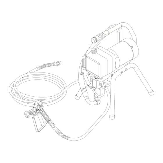
Model 231580
Advertisement
Table of Contents

Related Manuals for Graco 231580


Summary of Contents for Graco 231580
- Page 1 DURON Airless Paint Sprayers ELECTRIC, 120 VAC 3000 psi (210 bar, 21 MPa) Maximum Working Pressure Performance 395 Model 231580, Series A Standard mount; complete sprayer with hoses, gun, RAC IV DripLess Tip Guard and SwitchTip Performance 495 Model 232654, Series A Standard mount;...
-
Page 2: Table Of Contents
Warnings ........Component Identification and Function Setup . -
Page 3: Warnings
WARNING INJECTION HAZARD Spray from the gun, leaks or ruptured components can inject fluid into your body and cause extremely serious injury, including the need for amputation. Fluid splashed in the eyes or on the skin can also cause serious injury. Fluid injected into the skin is a serious injury. - Page 4 EQUIPMENT MISUSE HAZARD Equipment misuse can cause the equipment to rupture or malfunction and result in serious injury. INSTRUCTIONS This equipment is for professional use only. Read all instruction manuals, tags, and labels before operating the equipment. Use the equipment only for its intended purpose. If you are not sure, call your distributor. Do not alter or modify this equipment.
-
Page 5: Component Function And Identification
RAC IV Switch Tip Pressure Drain Valve Pressure Control Spray Gun Safety Latch Model 231580 shown DC motor, 120 Vac, 15A, 1 phase Transfers power from DC motor to the displacement pump Controls fluid outlet pressure Power switch that controls 120 Vac power to sprayer... -
Page 6: Setup
Remove any paint skin. Strain the paint through a fine nylon mesh bag (available at most paint dealers) to remove particles that could clog the spray tip. This is an important step toward trouble-free paint spraying. Model 231580 shown... -
Page 7: Operation
Grounding WARNING Improper installation or alteration of the grounding plug will result in a risk of electric shock, fire or explosion that could cause serious injury or death. 1. This equipment requires a 120 Vac, 60 Hz, 15A circuit with a grounding receptacle. See Fig. 3. How to use the gun trigger safety When engaged, the gun safety latch prevents the gun from accidental triggering. - Page 8 How to use the RAC IV tip guard. WARNING INJECTION HAZARD To reduce the risk of serious injury, whenever you are instructed to relieve pressure, follow the Pressure Relief Procedure on page 9. The tip guard alerts you to the risk and helps prevent placing any part of the body close to the spray tip.
-
Page 9: Pressure Relief Procedure
WARNING INJECTION HAZARD The system pressure must be manually relieved to prevent the system from starting or spraying accidentally. Fluid under high pressure can be injected through the skin and cause serious injury. To reduce the risk of an injury from injection, splashing fluid, or moving parts, follow the Pressure Relief Procedure whenever you: are instructed to relieve the pressure,... -
Page 10: Fire And Explosion Hazard
WARNING FIRE AND EXPLOSION HAZARD To reduce the risk of static sparking and splashing when priming or flushing the system, hold a metal part of the gun firmly to the side of a grounded metal pail before triggering the gun. 7. -
Page 11: Shutdown And Care
Shutdown and Care WARNING INJECTION HAZARD To reduce the risk of serious injury, whenever you are instructed to relieve pressure, follow the Pressure Relief Procedure on page 9. Shutdown and Care 1. Check the packing nut/wet-cup daily (102). Relieve pressure first. Keep the wet-cup 1/3 full of TSL at all times to help prevent fluid buildup on the piston rod and premature wear of packings. -
Page 12: Flushing
When to Flush 1. Before using a new sprayer: flush out the oil which was left in to protect pump parts. Before using water-base paint: flush with min- eral spirits followed by soapy water, and then a clean water flush. Before using oil-base paint: flush with mineral spirits only. -
Page 13: Motor Brush
INJECTION HAZARD To reduce the risk of serious injury, whenever you are instructed to relieve pressure, follow the Pres- sure Relief Procedure on page 9. Check everything in the troubleshooting table before disassembling the sprayer. TYPE OF PROBLEM WHAT TO CHECK If check is OK, go to next check Fluid pressure 1. -
Page 14: Flushing
Basic Problem Solving TYPE OF PROBLEM WHAT TO CHECK If check is OK, go to next check Electrical 5. Check motor armature commutator for burn (continued) spots, gouges and extreme roughness. Re- move motor cover and brush inspection plates to check. See page 19. 6. -
Page 15: Motor Brush
Intermediate Problem Solving TYPE OF PROBLEM WHAT TO CHECK If check is OK, go to next check Low output 3. Release gun trigger. Observe resting position of (continued) pump rod (107). 4. Check electrical supply with volt meter. Meter should read 105–125VAC. 5. -
Page 16: Motor Brush
Intermediate Problem Solving TYPE OF PROBLEM WHAT TO CHECK If check is OK, go to next check 1. Spray tip worn beyond sprayer pressure capa- Spray Pattern Variations bility. 2. Check transducer (29) for wear or damage. 3. Check pressure control (64) for smooth opera- tion. -
Page 17: Motor Brush
See page 19. If there is still uneven or no turning resistance, replace the motor. See page 22. Motor Test Fig. 12 BLACK/ WHITE BLACK Fig. 13 Model 231580 shown MOTOR... -
Page 18: General Repair Information
General Repair Information WARNING INJECTION HAZARD To reduce the risk of serious injury, whenever you are instructed to relieve pressure, follow the Pressure Relief Procedure on page 9. Tool List These are the tools required to service all parts of the sprayer. -
Page 19: Motor Brush
NOTE: Replace brushes when worn to about 0.5 in. (12.5 mm). Always check both brushes. Brush Repair Kit 236967, which includes spring clip 112766, is available for motors manufactured by Pacific Scientific. NOTE: Replacement brushes may last only half as long as the original ones. -
Page 20: Motor Brush
9. Test the brushes. a. Remove the pump connecting rod pin (17). See Fig. 18, page 21. b. With the sprayer OFF, turn the pressure con- trol knob fully counterclockwise to minimum pressure. Plug in the sprayer. c. Turn the sprayer ON. Slowly increase the pressure until the motor is at full speed. -
Page 21: Displacement Pump Repair
Displacement Pump Repair WARNING INJECTION HAZARD To reduce the risk of serious injury, whenever you are instructed to relieve pressure, follow the Pressure Relief Procedure on page 9. NOTE: Packing Repair Kit 235703 is available. Refer- ence numbers of parts included in the kit are marked with an asterisk, i.e., (121*). - Page 22 WARNING INJECTION HAZARD To reduce the risk of serious injury, whenever you are instructed to relieve pressure, follow the Pressure Relief Procedure on page 9. NOTE: See Fig. 21 except where noted. 1. Relieve pressure. 2. Try to stop the pump with the piston rod (107) in its lowest position.
-
Page 23: Motor Start Board
Motor Start Board WARNING INJECTION HAZARD To reduce the risk of serious injury, whenever you are instructed to relieve pressure, follow the Pressure Relief Procedure on page 9. NOTE: See Fig. 22 for this procedure. 1. Relieve pressure. 2. Remove the junction box screws (56) and lower the junction box (59). -
Page 24: Drive Housing, Connecting Rod, Crankshaft
Drive Housing, Connecting Rod, Crankshaft WARNING INJECTION HAZARD To reduce the risk of serious injury, whenever you are instructed to relieve pressure, follow the Pressure Relief Procedure on page 9. NOTE: Inspect parts as they are removed. Replace parts that are worn or damaged. 1. - Page 25 Drive Housing, Connecting Rod, Crankshaft Torque to 80 in–lb (9 N.m) Quantity of three Quantity of one Apply a total of 3 fl. oz.(29 cc) of grease to gears. Note: Filter not shown Fig. 24 REF A 02815...
-
Page 26: Pressure Control
WARNING INJECTION HAZARD To reduce the risk of serious injury, whenever you are instructed to relieve pressure, follow the Pressure Relief Procedure on page 9. NOTE: See Fig. 25 for this procedure. NOTE: The pressure control (64) cannot be repaired or adjusted. -
Page 27: Pressure Transducer
Pressure Transducer WARNING INJECTION HAZARD To reduce the risk of serious injury, whenever you are instructed to relieve pressure, follow the Pressure Relief Procedure on page 9. NOTE: See Fig. 26 for this procedure. 1. Remove the displacement pump. See page 21. 2. -
Page 28: Drain Valve
WARNING INJECTION HAZARD To reduce the risk of serious injury, whenever you are instructed to relieve pressure, follow the Pressure Relief Procedure on page 9. Fig. 28 1. Turn the handle (45) to the closed position. Drive out the pin (44). Remove the handle. 2. -
Page 29: Technical Data
0–3000 psi (0–210 bar, 21 MPa) Motor Model 231580 ....... . . -
Page 30: Sprayer Parts Drawing
Sprayer Parts Drawing Model 231580, Series A Model 232654, Series A Label See detail on page 31 REF 33 REF 32 INSIDE LABEL HOSE AND GUN NOT SHOWN IN PROPORTION TO SPRAYER... -
Page 31: Sprayer Parts List
Sprayer Parts List Model 231580, Series A, Model 232654, Series A Ref. Part No. Description 111700 GRIP. handle MOTOR KIT Includes items 4a to 4g 236965 Model 231580 237458 Model 232654 100069 . BALL, sst, 1/4 in. dia. 111616 . TERMINAL, flat, 1/4 in. (f), 18 awg 107503 . - Page 32 Sprayer Parts Drawing Model 232655, Series A OUT- SIDE LABEL INSIDE LABEL Label See page 33 for detail...
- Page 33 Sprayer Parts List Model 232655, Series A Ref. Part No. Description 192027 SLEEVE, cart 237458 MOTOR KIT Includes items 4a to 4f 100069 . BALL, sst, 1/4” dia. 111616 . TERMINAL, flat, 1/4” (f), 18 awg 107503 . TERMINAL, 3/16” (m), 16 awg 187784 .
-
Page 34: Graco Warranty
Graco Warranty Graco warrants all equipment listed in this manual which is manufactured by Graco and bearing its name to be free from defects in material and workmanship on the date of sale by an authorized Graco distributor to the original purchaser for use. With the ex ception of any special extended or limited warranty published by Graco, Graco will, for a period of twelve months from the date of sale, repair or...
Need help?
Do you have a question about the 231580 and is the answer not in the manual?
Questions and answers