Table of Contents
Advertisement
Quick Links
Advertisement
Table of Contents

Related Manuals for red lion APOLLO IMR Series


Summary of Contents for red lion APOLLO IMR Series
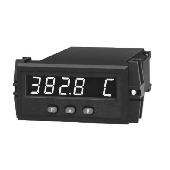
- Page 1 THE APOLLO INTELLIGENT METER SERIES MODEL IMR INSTRUCTION MANUAL...
- Page 2 Red Lion Controls the leader in today’s industrial market. Red Lion Controls has a complete line of industrial indication and control equipment, and we look forward to being of service to you now and in the future.
-
Page 3: Table Of Contents
Table of Contents SAFETY INFORMATION · · · · · · · · · · · · · · · · · · · · · · · · · · · · · · · · · · · · · · · · · · · · · · · · · · · · · · · · · · · · · · 3 Safety Summary ·... - Page 4 Communication Format · · · · · · · · · · · · · · · · · · · · · · · · · · · · · · · · · · · · · · · · · · · · · · · · · · · · · · · · · · · · 28 Sending Commands to the IMR ·...
-
Page 5: Safety Information
SAFETY INFORMATION SAFETY SUMMARY All safety related regulations, local codes and instructions that appear in the manual or on equipment must be observed to ensure personal safety and to prevent damage to either the instrument or equipment connected to it. If equipment is used in a manner not specified by the manufacturer, the protection provided by the equipment may be impaired. -
Page 6: General Description
GENERAL DESCRIPTION The Apollo Intelligent RTD Meter (IMR) accepts standard RTD inputs and requirements for washdown applications, when properly installed. Plug-in style precisely linearizes them into temperature readings. A full 6-digit display terminal blocks simplify installation wiring and change-outs. accommodates a wide range of temperature inputs and holds large totalization values. -
Page 7: Block Diagram
BLOCK DIAGRAM Note: Analog “-” and Alarm common are separate and isolated from the signal common. The commons should NOT be tied together. -
Page 8: Programming And Operating The Imr
PROGRAMMING AND OPERATING THE IMR PROGRAMMING THE IMR Although the unit has been programmed at the factory, the set-ups will generally have to be changed to suit the application. Basic set-up is complete after units of temperature selection, decimal point selection, and digital filtering level selection. Before actually trying to program the indicator, it is advised to organize all the data for the programming steps to avoid any possible confusion and to read the programming procedure entirely before proceeding. - Page 9 DISPLAY RESULT OF “P” BUTTON DISPLAY RESULT OF “P” BUTTON “Pro” < > “0” - Causes the indicator to return to normal display mode. Any “Pro” < > “5” - This module sets the time base, scale factor and low temperature changes to set-up data are permanently stored in the E PROM.
-
Page 10: Module #1 - Program Rtd Type, Temperature Scale (F Or C)
MODULE #1 - PROGRAM RTD TYPE, TEMPERATURE SCALE (F OR C) AND DECIMAL POINT POSITION Select the desired RTD type by pressing the “UP” or “DOWN” button. “rtdtyP” < > “385” “392” Select the desired temperature scale by pressing the “UP” or “DOWN” button. -
Page 11: Module #3 - Program Functions Accessible W/ Front Panel Lockout
MODULE #3 - PROGRAM FUNCTIONS ACCESSIBLE W/ FRONT PANEL LOCKOUT RESET LATCHED ALARMS This programming module programs what is accessible through the front panel when the PGM. DIS. pin is connected to common (COMM.). If the alarm option is installed and if either alarm is programmed to latch, this Note: The term “Quick Programming”... - Page 12 RESET TOTAL (cont’d)* Depending on functions selected under Pro 3 and Pro 6, alarms, hysteresis, peak, and valley values can be monitored and/or changed when PGM. DIS. is tied to COMM. This provides a “QUICK PROGRAMMING” method for “day to day” process changes.
-
Page 13: Module #4 - Program Digital Filter And Remote Input
MODULE #4 - PROGRAM DIGITAL FILTER AND REMOTE INPUT PROGRAM DIGITAL FILTERING “1” - A negative going edge resets the contents of the totalizer to zero. If the displayed process signal is difficult to read due to small process Totalization commences regardless of the state of the input. variations or noise, increased levels of filtering will help to stabilize the display. - Page 14 PROGRAM FUNCTION OF E1-CON AND OPTIONAL E2-CON PIN (Cont’d) “9” - If the alarm option is installed, a low level resets a latched or unlatched alarm into its inactive state. This provides manual override of alarms for system start-up and other unusual events such as system testing.
-
Page 15: Module #5 - Program Integrator/Totalizer
MODULE #5 - PROGRAM INTEGRATOR/TOTALIZER TB = If Program Select Number Chosen Is: Enter in Formula Programming for the integrator/totalizer consists of four programming steps: “0” for sec. totalizer decimal point position, time base, scale factor and low temperature “1” for min. disable. -
Page 16: Module #6 - Program Alarm/Setpoint
MODULE #6 - PROGRAM ALARM/SETPOINT ALARM #1 ASSIGNMENT TO INPUT OR If the alarm option is installed, this module is used to configure the operation of INTEGRATOR/TOTALIZER the alarms to a variety of combinations. The programmable options are HI/LO acting, auto/manual reset (latching), tracking, assignment to input or Alarm #1 may be programmed to activate on either the input or the integrator/totalizer, display alarms, alarm values and hysteresis (deadband) values. - Page 17 ALARM #2 ASSIGNMENT TO INPUT OR INTEGRATOR/ TOTALIZER Alarm #2 may be programmed to activate on either the input or the integrator/totalizer value. If the integrator/totalizer option is not installed, this step defaults to the input. “ASN-2” < > “INPUt”or “totAL” PROGRAM VALUE FOR ALARM #2 The range of the alarm value is -999 to 9,999 for the input display and -99999 to 999999 for the totalizer option display.
-
Page 18: Module #7 - Program Serial Communications
MODULE #7 - PROGRAM SERIAL COMMUNICATIONS Several programmable parameters must be programmed before serial “Print” < > “0” - input signal communication can occur. “1” - input signal, peak, valley and offset “2” - input signal and alarm 1 and alarm 2 BAUD RATE “3”... -
Page 19: Module #8 - Program Re-Transmitted Analog Output
MODULE #8 - PROGRAM RE-TRANSMITTED ANALOG OUTPUT This programming module allows digital scaling of the 4 to 20 mA or 0 to 10 VDC analog output. The type of analog output is determined by the Model ordered. (See Ordering Information for available models.) The display value at which 4 mA or 0 VDC and the display value at which 20 mA or 10 VDC are transmitted are keyed-in. -
Page 20: Module #9 - Service Operations
MODULE #9 - SERVICE OPERATIONS The indicator has been fully calibrated at the factory. If the unit appears to be Indicator calibration is complete. It is recommended that calibration be indicating incorrectly or inaccurately, refer to the troubleshooting section before checked by comparing the displayed temperature with a precision thermometer. -
Page 21: Operating The Imr
OPERATING THE IMR To reset: While “PEA” or “VAL” is being displayed, After completing all set-up operations, the unit is ready to install and operate. press and hold “DOWN” and press “P”. Pressing After power is applied, a display test consisting of illuminating all segments for 2 “P”... -
Page 22: Factory Configuration
FACTORY CONFIGURATION The following chart lists the programming of the unit when shipped from the factory. (In Program Module #9, Code 66 will restore the unit to these values.) “Pro 1”..“rtdtYP” “385” “Pro 6”..“trAc” “NO” “SCALE” “F” “dISP” “NO” “dECPNt” “0.0”... -
Page 23: Programming Example
PROGRAMMING EXAMPLE “Pro 4”..“FILter” Enter 0 “E1-CON” Enter 7 (reset alarm #2) As an example of a programming sequence, the following values, gained from “E2-CON” Enter 14 (print request) a temperature-time monitoring application, are programmed into the indicator. DISPLAY: Display the actual temperature of a liquid solution in °F. “Pro 5”..“tbASE”... -
Page 24: Temperature Monitoring Example
TEMPERATURE MONITORING EXAMPLE An IMR is installed as a monitoring device and back-up controller for a freezer storage facility. Normally, the freezer temperature is maintained at about -29°C ±2°. The absolute maximum allowable temperature of the freezer is 0°C. In the event of a system failure, alarm output #1 of the IMR is programmed to start a secondary cooling system should the temperature reach 0°C. -
Page 25: Process Control Example
PROCESS CONTROL EXAMPLE Four IMRs are used to control a Plastic Injection Molding Process. The raw material (Thermo-Plastic Resin) is contained in a bulk storage bin and is removed and prepared for mold injection by a screw feed. While the material is in the screw feed, band heaters, placed around the screw barrel and controlled by IMR RTD indicators, gradually melt the material. -
Page 26: Integrator /Totalizer / Peak/Valley/ Temperature Offset (Optional)
INTEGRATOR /TOTALIZER / PEAK/VALLEY/ TEMPERATURE OFFSET (Optional) INTEGRATOR/TOTALIZER stored at power-down to span over shifts, days, etc. An external input can be programmed to reset or engage the unit into a peak/valley reading indicator. The integrator/totalizer option simply adds input readings together using a Additionally, the peak and valley can be viewed and reset from the front panel, if programmable time base and scaling coefficient. -
Page 27: Integrator/Totalizer Example
Example: The meter is displaying 502 degrees and 696 degrees (actual temperature) S.F. = Programmable Scale Factor when the calibrated temperature reference shows that 500 degrees and 700 D.T. = Desired Totalizer value for a degrees respectively should be displayed (desired temperature). fixed time duration T.B. - Page 28 INTEGRATOR/TOTALIZER SET-UP (Cont’d) The integrator/totalizer will accumulate up to 99999.9. At the end of the shift, the average temperature over the previous 8 hours can be read directly. The integrator/totalizer can then be reset for the next eight hour shift. Anytime during the shift, the average temperature can be calculated by the following formula: I.V.
-
Page 29: Alarms (Optional)
ALARMS (Optional) The alarm option consists of an additional printed circuit board with nine (Alarm #2) automatically changes Alarm #1 so that the offset between Alarm #2 and terminals. Six of these terminals are the two Form-C relays and the other three are Alarm #1 remains the same. -
Page 30: Ma Current Loop Serial Communications (Optional)
SO+ and SO-. Before serial communication can take place, the indicator must be Additionally, multiple units and other Red Lion Controls instruments can be programmed to the same baud rate as the connected equipment. In addition, the serially addressed, up to a maximum of 99 units. -
Page 31: Sending Commands To The Imr
SENDING COMMANDS TO THE IMR The command string is constructed in a specific logical sequence. The indicator will reject command strings that do not conform. Only one operation When sending commands to the unit a command string must be constructed. can be performed per command string. - Page 32 If illegal commands or character is sent to the IM, an asterisk (*) must be sent to Timing Diagrams clear the input buffer. The IM will not respond to an illegal or incomplete (Full Transmission Selected) transmission. The diagrams show the difference in the timing considerations for either Abbreviated or Full Character Transmission, or if a Reset Command is issued.
-
Page 33: Receiving Data From The Imr
RECEIVING DATA FROM THE IMR If the transmitted data is overrunning the peripheral’s buffer, the receive channel to the indicator may be used for handshaking purposes. As a Data is transmitted from the indicator whenever a “T” or “P” command is consequence of this, even if the indicator is to transmit only (ex. -
Page 34: Current Loop Installation
CURRENT LOOP INSTALLATION WIRING CONNECTIONS It is recommended that shielded (screened) cable be used for serial communications. This unit meets the EMC specifications using Alpha #2404 cable or equivalent. There are higher grades of shielded cable, such as four conductor twisted pair, that offer an even higher degree of noise immunity. When wiring the 20 mA current loop, remove the bottom terminal block (TBA), located on the rear of the unit. -
Page 36: Re-Transmitted Analog Output (Optional)
RE-TRANSMITTED ANALOG OUTPUT (Optional) The re-transmitted analog output option transmits a digitally programmable 4 voltage ranges can be supported by calculating the slope and intercept of the to 20 mA or 0 to 10 VDC signal to drive chart recorders, remote indicators and display/output and calculating the required display values at 4 mA (0 VDC) and 20 mA (10 VDC). -
Page 37: Analog Output Calibration
ANALOG OUTPUT CALIBRATION Although the analog output has been calibrated at the factory, zero and span adjustments are provided to compensate for small offsets and drifts. If excessive drift is noticed, the following calibration procedure may be performed. Scale the analog output by entering an arbitrarily larger display value for “AN-HI”... -
Page 38: Appendix "A" - Installation & Connections
APPENDIX “A” - INSTALLATION & CONNECTIONS INSTALLATION ENVIRONMENT Do not use tools of any kind (screwdrivers, pens, pencils, etc.) to operate the keypad of the unit. The unit should be installed in a location that does not exceed the maximum Before installing the IM into the panel, the user should first become familiar operating temperature and provides good air circulation. -
Page 39: Emc Installation Guidelines
EMC INSTALLATION GUIDELINES 5. In extremely high EMI environments, the use of external EMI suppression devices, such as ferrite suppression cores, is effective. Install them on Although this unit is designed with a high degree of immunity to Signal and Control cables as close to the unit as possible. Loop the cable ElectroMagnetic Interference (EMI), proper installation and wiring methods must through the core several times or use multiple cores on each cable for be followed to ensure compatibility in each application. -
Page 40: Wiring Connections
WIRING CONNECTIONS Basic Connection After the unit has been mechanically mounted, it is ready to be wired. All conductors should meet voltage and current ratings for each terminal. Also cabling should conform to appropriate standards of good installation, local codes and regulations. -
Page 41: Output Wiring
OUTPUT WIRING Relay Connections To prolong contact life and suppress electrical noise interference due to the switching of inductive loads, it is good installation practice to install a snubber across the contactor. Follow the manufacturer’s instructions for installation. Note: Snubber leakage current can cause some electro-mechanical devices to be held ON. -
Page 42: Appendix "B" - Specifications And Dimensions
APPENDIX “B” - SPECIFICATIONS AND DIMENSIONS 1. DISPLAY: 4-digit with F© indication, 0.56" (14.2 mm) high LED, minus 7. ACCURACY: 0.3°C, @ 23°C and 20 min. Warm-up. sign displayed for negative temperatures. 6-digits for integrator/ totalizer. 8. RANGE: 0.1° res: -99.9° to 850.0°C (-99.9° to 999.9°F) “Flashing”... - Page 43 APPENDIX “B” - SPECIFICATIONS AND DIMENSIONS 16. ENVIRONMENTAL CONDITIONS: Relays: Operating Temperature Range: 0 to 50°C Type: Form C (2) Max. Rating: 5 Amps @ 120/240 VAC or 28 VDC (resistive load), 1/8 Storage Temperature Range: -40 to 80°C hp @ 120 VAC (inductive load). Span Drift: 50 ppm/°C Relay Life Expectancy: 100,000 cycles at max.
- Page 44 21. CERTIFICATIONS AND COMPLIANCES: SAFETY IEC 61010-1, EN 61010-1: Safety requirements for electrical equipment for measurement, control and laboratory use, Part 1. IP65 Enclosure rating (Face only), IEC 529 Type 4 Enclosure rating (Face only), UL50 ELECTROMAGNETIC COMPATIBILITY Immunity to EN 50082-2 Electrostatic discharge EN 61000-4-2 Level 2;...
-
Page 45: Appendix "C" - Troubleshooting Guide
APPENDIX “C” - TROUBLESHOOTING GUIDE The majority of all problems with the indicator can be traced to improper For further technical assistance, contact technical support at the appropriate connections or improper programming set-ups. Be sure all connections are clean company numbers listed on the back cover of the instruction manual. and tight and check the programming set-ups for correct data. -
Page 46: Appendix "D" - Programmable Functions
APPENDIX “D” - PROGRAMMABLE FUNCTIONS Programming of the indicator is divided into modular steps. Each module is a “Pro 4” - PROGRAM DIGITAL FILTERING AND REMOTE short sequence of data entries. The front panel buttons “UP” and “DOWN” INPUT FUNCTION (shown as “arrows”... - Page 47 APPENDIX “D” - PROGRAMMABLE FUNCTIONS (Cont’d) “Pro 6” - PROGRAM ALARMS “trAc” Enable alarm value tracking “Pro 8” - PROGRAM RE-TRANSMITTED ANALOG OUTPUT “ ASIN” Select source of analog output (input or total) “dISP” Enable display alarm annunciators “ AN-Lo” Enter 4 mA or 0 VDC display value “LAtC-1”...
-
Page 48: Appendix "E" - Ordering Information
APPENDIX “E” - ORDERING INFORMATION PART NUMBERS FOR TOTALIZER/ AVAILABLE SUPPLY MODEL ALARM SERIAL ANALOG DESCRIPTION PEAK/VALLEY VOLTAGES OUTPUT OUTPUT OUTPUT SLOPE/OFFSET 115/230 VAC IMR00160 IMR00162 IMR02160 IMR02161 Intelligent Meter for RTD Inputs IMR02162 4 to 20 mA IMR02163 4 to 20 mA IMR02167 0 to 10 VDC IMR02169... - Page 49 This page is intentionally left blank. -47-...
- Page 50 This page is intentionally left blank. -48-...
- Page 51 The Company’s option. The Company disclaims all liability for any affirmation, promise or representation with respect to the products. The customer agrees to hold Red Lion Controls harmless from, defend, and indemnify RLC against damages, claims, and expenses arising out of subsequent sales of RLC products or...
- Page 52 IMR/IM-L 10/05 DRAWING NO. LP0187 Apollo Intelligent Meter for RTD Inputs - IMR Instruction Manual Red Lion Controls AP Red Lion Controls Red Lion Controls BV 31, Kaki Bukit Road 3, 20 Willow Springs Circle Basicweg 11b #06-04/05 TechLink York PA 17402...
Need help?
Do you have a question about the APOLLO IMR Series and is the answer not in the manual?
Questions and answers