Table of Contents
Advertisement
Quick Links
Advertisement
Table of Contents

Subscribe to Our Youtube Channel
Related Manuals for Setra Systems MRMS


Summary of Contents for Setra Systems MRMS
- Page 1 Multi-Room Monitoring Station (MRMS) User’s Guide...
- Page 2 The material in this document is for information purposes only and is subject to change without notice. Setra Systems, Inc assumes no responsibility for any errors or for consequential damages that may result from the use or misrepresentation of any of the material in this publication.
-
Page 3: Table Of Contents
– – – – – – – –... -
Page 4: Overview
Setra Pressure and Condition Room Monitors such as Models SRPM or SRCM. The MRMS user interface is simple, intuitive and allows the user to access configuration setup menus using the backlit color TFT LCD (480 x 272 resolution) display with a resistive touch panel. -
Page 5: Intended Use
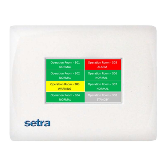
1.1.1. Intended Use The MRMS can be installed in a centralized location such as a nurse’s station in healthcare applications or a centralized control room for applications within Pharmaceutical clean room, Biological Safety Labs, and Vivariums. The MRMS provides remote viewing and... - Page 6 User Interface: LCD Display 480 x 272 TFT/WQVGA module, with LED backlight and 4-wire resistive touch-screen. Home Screen Room label Standby (No Isolation) condition Alarm condition Normal condition The individual room screen shows the condition of each individual room being monitored, including pressure, temperature, humidity or any user defined parameter defined on the remote SRCM.
- Page 7 Room Auto Discover: This function is used to scan and search for SRPM and SRCM devices on the BACnet® network. A list of devices found and their corresponding MAC address will be display after performing a Room Auto Discover search. Up to eight (8) rooms can be selected from the list and the room location is configurable.
-
Page 8: Required Parts
Mating electrical connectors, Phoenix contact MC plug kit, Qty: 2 (Communications connector and power connector) Installation instructions, Qty: 1 Quick start operation guide, Qty: 1 Installation The MRMS is designed to be mounted in a standard triple gang-double deep electrical box RACO 697 or Appleton M3-350 or equivalent. -
Page 9: Wiring Recommendations
Wall Mount Installation Overview Note: Secure the triple gang-double deep electrical box to the stud(s) using the mounting hole in the side of the electrical box (see figure above for mounting hole location). Drive the mounting screws from the inside of the electrical box into the wall studs to prevent sharp objects protruding into the electrical box. -
Page 10: Wiring Electrical Box (Rough-In)
Use only the knockouts at the back of the rough in box. The front knockouts will be inaccessible once the MRMS is installed. Strain relief tubing and wires, and seal box as required. Tripe gang electrical box rough wiring and plumbing 2.3.3. - Page 11 The back of the MRMS has electrical connectors labeled with their function. The mating electrical connectors (supplied) are color coded, keyed, and labeled with the matching function. Power, labeled POWER, L1, L2, ground symbol Starting with the 3-pin Power connector, connect the 24 VAC lines to L1 and L2. Connect a ground wire, GND, from a ground lug in the 3 gang box to the GND on the connector.
-
Page 12: Touchscreen Operation
The second mode of operation is the Administrative Menu (Menu) screen, which permits setup and configuration for the MRMS units. After changes have been performed on the Menu screen, functions are saved and operation returns to the Home screen. Many administrative settings can be written over the BACnet MS/TP network. -
Page 13: Home Screen
3.2 Home Screen When in the Home screen, the MRMS will show the rooms that have been configured for monitoring. At a glance, the user can see if any room is in a normal state (green), warning state (yellow) or alarm state (red). If the user wants to view room status, all they have to do is touch the main display screen on the room they want to view. -
Page 14: Room Screen
The Room Label at the top of the screen can be defined by the user to ensure the viewer understands which room is actively being monitored by the MRMS. See Auto Discover Results menu in Network Setup menu to enter text for your specific room. -
Page 15: Administrative Menu Screen
Pressing the MENU button on the Home screen or Room screen brings up the Administrative Menu. If passwords are enabled, the user is required to enter the correct password before being authorized to make changes. From the Administrative Menu, the user can set all operating parameters of the MRMS. 3.4.1. Setup Unit Menu... -
Page 16: U D I B L E A L A R M
Press anywhere in the Unit label selection box to bring up the on-screen keyboard to enter the MRMS text desired. It is not necessary to touch the white area next to user text, simply start entering data using the keyboard. Be sure to press the Enter button under the text entered before leaving this screen. -
Page 17: U P E R V I S O R P A S S W O R D
3.4.1.4. Number of Rooms The maximum number of rooms that can be configured is eight (8). Depending on the amount of rooms configured, the MRMS Home screen will look like the following: One Room Two Rooms Three Rooms Four Rooms... -
Page 18: Network Setup
Note: The master Supervisor password is 351, and will work for any condition where a user may need to reset passwords. 3.5 Network Setup Note: If you are planning to use the USB Configuration Cloning feature, follow that process first before network setup. Otherwise, the cloning process will overwrite network information and affect MS/TP communications. - Page 19 1. BACnet configuration requires the user to configure the following parameters Baud Rate - User can select any one of the four standard baud rates for RS485 communication from 9600 (default), 19200, 38400 and 76800 by using the Change button. Auto baud feature is not supported. MAC Address - User can enter MAC address specific to this device by touching on this field.
- Page 20 4. Once this is complete disable the BACnet setup by moving the dip switch position 1 to off (left) position. Five position dip sw itch location 5. Press Save and Exit. 6. After the unit returns to the main menu screen, disconnect the power to the unit and reconnect in order to boot-up with the proper MAC address and Device Instance.
-
Page 21: System Information
3.6 System Information Note: If The System Information screen reports Model Number, Serial Number, Firmware Revision, Network Status and Technical Support Contact. Technical Support Any string 30 characters or shorter can be entered in this field by pressing anywhere in the white text entry box to enable the pop-up keyboard. Enter an email address, name, or phone number as needed. -
Page 22: Usb Configuration Cloning
Otherwise, the cloning process will overwrite network information and affect MS/TP communications. The MRMS has a USB port built in for the purpose of duplicating configurations when multiple units are being setup with similar configurations. To use this func-tion, a USB 2.0 thumb drive of capacity 256 megabytes or larger must be used. - Page 23 As soon as the thumb drive is connected to the MRMS, it will be recognized and bring up a Drive Connected menu. 1. Select Configuration Write to transfer the master MRMS configuration from the unit to the thumb drive Note: The configuration file is labeled PCCONFIG.txt.
-
Page 24: Updating Firmware
3.9 Updating Firmware The USB port can also be used for upgrading the MRMS firmware in the field. To upgrade the firmware you must first download the firmware for the latest versions of the hex file for the host controller, the USB hex file and the BACnet hex file, these are Host1924.hex, USB1924.hex and BAC1924.hex. - Page 25 User cannot enter into menus User has lost password. Use default password "351". because of password protection. MRMS does not come online Two or more controllers have the Modify each duplicate address to a same MAC address. unique number.
- Page 26 RETURNING PRODUCTS FOR REPAIR When returning a product to Setra Systems, the material should be carefully packaged and shipped prepaid Setra Systems, Inc. 159 Swanson Rd. Boxborough MA 01719-1304 ATTN: Repair Department To assure prompt handling, please refer to return instructions on our website at http://www.setra.com/contact-us/calibration/...
Need help?
Do you have a question about the MRMS and is the answer not in the manual?
Questions and answers