Manitowoc National Crane 500E2 Operator's Manual
Hide thumbs
Also See for National Crane 500E2:
- Operator's manual supplement (94 pages) ,
- Service manual (162 pages)
Table of Contents
Advertisement
Quick Links
Advertisement
Table of Contents

Related Manuals for Manitowoc National Crane 500E2


Summary of Contents for Manitowoc National Crane 500E2
- Page 1 National Crane 500E2 Operator Manual 9869...
- Page 2 WARNING California Proposition 65 Breathing diesel engine exhaust exposes you to chemicals known to the State of California to cause cancer and birth defects or other reproductive harm. • Always start and operate the engine in a well-ventilated area. • If in an enclosed area, vent the exhaust to the outside.
- Page 3 OPERATOR MANUAL This manual has been prepared for and is considered part of the 500E2 This Manual is divided into the following sections: SECTION 1 INTRODUCTION SECTION 2 SAFETY PRECAUTIONS SECTION 3 OPERATING CONTROLS AND PROCEDURES SECTION 4 SET-UP SECTION 5 LUBRICATION PROCEDURE AND CHARTS SECTION 6 MAINTENANCE CHECKLIST...
- Page 4 THIS PAGE BLANK...
-
Page 5: Table Of Contents
500E2 OPERATOR MANUAL TABLE OF CONTENTS SECTION 1 ..........Introduction General . - Page 6 TABLE OF CONTENTS OPERATOR MANUAL 500E2 Working ............2-32 Lifting .
- Page 7 500E2 OPERATOR MANUAL TABLE OF CONTENTS Hydraulic Capacity Alert System ......... . . 3-9 System Description .
- Page 8 TABLE OF CONTENTS OPERATOR MANUAL 500E2 Extreme Pressure Multipurpose Gear Lubricant (EPGL)..... 5-2 Open Gear Lubricant ..........5-2 Antifreeze/Coolant (for Cab Heater) .
- Page 9 500E2 OPERATOR MANUAL TABLE OF CONTENTS Hydraulic System ..........6-15 Reservoir.
- Page 10 TABLE OF CONTENTS OPERATOR MANUAL 500E2 THIS PAGE BLANK...
-
Page 11: Section 1
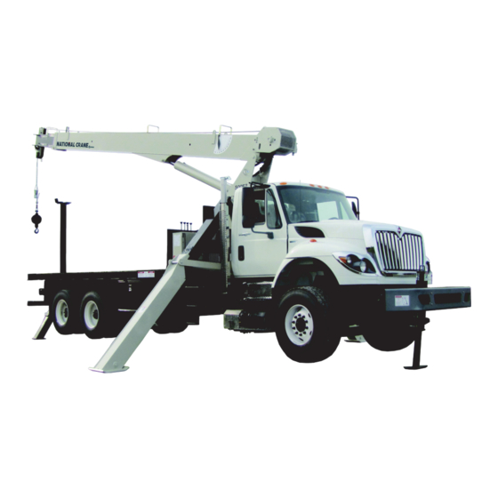
If you are the new owner of a National crane, please register your satisfaction with our products and customer support. it with Manitowoc Crane Care so we have the ability to Your local distributor is the best equipped and most contact you if the need arises. - Page 12 INTRODUCTION OPERATOR MANUAL 500E2 FIGURE 1-1 500E2 Series Major Components Item Component Item Component Stabilizers Hoist Hydraulic Reservoir Boom Control Console Sheaves Outriggers Boom Rest NOTICE TO OWNER/USER Should this crane become involved in a property damage accident, please contact your local National Crane distributor immediately and relate details of incident including serial number of crane.
-
Page 13: Safety Messages
500E2 OPERATOR MANUAL SAFETY PRECAUTIONS SECTION 2 SAFETY PRECAUTIONS SECTION CONTENTS Safety Messages......2-1 Personnel Handling. -
Page 14: General
National Crane distributor must be immediately advised of the incident and consulted on necessary inspections and repairs. Should the distributor not be immediately available, contact should be made directly with Manitowoc Product Safety at the address below. The equipment must not be CAUTION... -
Page 15: Operator Qualifications
500E2 OPERATOR MANUAL SAFETY PRECAUTIONS each person responsible for assembly, disassembly, decals on the equipment. Decals provide important operation and maintenance of the equipment. instructions and warnings and must be read prior to any operational or maintenance function. No personnel shall be allowed to climb onto the equipment or enter the cab or operator’s station unless performance of Refer to the Parts Manual for this equipment for the locations their duties require them to do so, and then only with... -
Page 16: Operational Aids
SAFETY PRECAUTIONS OPERATOR MANUAL 500E2 You must be mentally and physically fit to operate • When an Anti-Two-Blocking Device, Two-Blocking equipment. Never attempt to operate equipment while under Damage Prevention Device or Two-Block Warning the influence of medication, narcotics, or alcohol. Any type of Device is inoperative or malfunctioning, the designated drug could impair physical, visual and mental reactions, and person responsible for supervising the lifting operations... -
Page 17: Working Area Limiter (If Equipped)
500E2 OPERATOR MANUAL SAFETY PRECAUTIONS Two-blocking occurs when the load block (hook block, the boom is lowered. Keep load handling devices a minimum headache ball, rigging, etc.) comes into physical contact with of 107 cm (42 in) below the boom nose at all times. the boom (boom nose, sheaves, jib, etc.). -
Page 18: Load Charts
SAFETY PRECAUTIONS OPERATOR MANUAL 500E2 Load Charts Load Charts represent the absolute maximum allowable loads, which are based on either tipping or structural limitations of the equipment under specific conditions. Knowing the precise load radius, boom length, and boom angle should be a part of your routine planning and operation. -
Page 19: Wind Speeds
500E2 OPERATOR MANUAL SAFETY PRECAUTIONS NOTE: The wind speed corresponding to the Beaufort scale in the table is mean wind speed at 10 m (33 ft) elevation over a period of 10 minutes. Table 2-1 Beaufort Wind Scale Maximum Wind Speed Beaufort Visible Indicator Description... - Page 20 SAFETY PRECAUTIONS OPERATOR MANUAL 500E2 Simplified Method to Determine Maximum Permissible Wind Speed Determine 3-Second Gust 0.14 V(z) = [(z/10) + 0.4]v [m/s] Wind Speed at boom tip, 0.14 V(z) = [(z/33) + 0.4]v [mph] V(z) 13.4 m/s < V(z) < 20.1 m/s V(z) >...
- Page 21 500E2 OPERATOR MANUAL SAFETY PRECAUTIONS Determination of 3-second wind gust speed at boom Size and Shape of the load: tip height: These rated capacities are also based on the assumption that the Wind Resistance Area of load, Awr is not more The following example illustrates how to calculate 3-second (load) wind gust speed at boom tip height based on mean wind...
- Page 22 SAFETY PRECAUTIONS OPERATOR MANUAL 500E2 Calculation of Projected Wind Area (Ap) Wind Wind = 8 m = 24 m 25 ft 25 ft Wind Wind 10 ft 3 ft = 75 ft = 250 ft 10 ft 3 ft 8384-1 FIGURE 2-2 Determining Wind Drag Coefficient (Cd) If the exact Wind Drag Coefficient of a shape is not known,...
- Page 23 500E2 OPERATOR MANUAL SAFETY PRECAUTIONS Table 2-2 Wind Drag Coefficient Maximum Permissible Wind Speed If the wind resistant area of the load Awr is greater than (load) Shape the allowable wind resistant area Awr , the ratio can be (allow) used to determine a permissible wind speed V(z) for the load 1.1 to 2.0 using Table 2-3.
- Page 24 SAFETY PRECAUTIONS OPERATOR MANUAL 500E2 Rated Load Chart Example - Metric 8383-1 FIGURE 2-3 2-12 Published 07-26-2019 Control # 111-06...
- Page 25 500E2 OPERATOR MANUAL SAFETY PRECAUTIONS Table 2-4 Example-Capacity Reduction Factors for Wind Speed V(z) Greater than 13.4 m/s - Metric (Only for lifting with main boom on fully extended outriggers, with or without stowed extension) For wind speed V(z) (3-second gust speed at boom tip height) V(z) > 13.4 m/s ≤ 20.1 m/s, the Reduced Capacity shall be calculated by multiplying the Published Rated Capacity by the following factors: Main Boom Length in Meters Wind Speed...
- Page 26 SAFETY PRECAUTIONS OPERATOR MANUAL 500E2 At wind speeds greater than 13.4 m/s, it is not permissible to Load example 1.3a: lift a load greater than 12,040 kg, even if the wind resistance With large wind resistance area of the load Awr (load) area of the load is less than 14.45 m •...
- Page 27 500E2 OPERATOR MANUAL SAFETY PRECAUTIONS • Is the load to be lifted less than allowable load? Ratio = 1.37 8,000 kg ≤ 12,040 kg • Is Awr less than Awr (load) (allow) From Table 2-5, the maximum permissible wind speed at 19.83 m ≤...
- Page 28 SAFETY PRECAUTIONS OPERATOR MANUAL 500E2 Rated Load Chart Example - Non-metric 8382-1 FIGURE 2-4 2-16 Published 07-26-2019 Control # 111-06...
- Page 29 500E2 OPERATOR MANUAL SAFETY PRECAUTIONS Refer to the above equipment configuration for the following load conditions: Example and Sample Calculations (Non-metric) Load example 2.1: The following example illustrates how to calculate allowable load while operating in wind speed (3-second wind gust With known Wind Drag Coefficient of the load Cd, speed) above 13.4 m/s (30 mph) and maximum permissible •...
-
Page 30: Lifting Operations
SAFETY PRECAUTIONS OPERATOR MANUAL 500E2 the wind resistance area of load can be estimated as: • Is Awr less than Awr (load) (allow) 216 ft ≤ 149 ft ......NO = Ap x Cd = 180 x 1.2 = 216 ft (load) Conclusion: This load is NOT permissible to lift in wind... -
Page 31: Counterweight
500E2 OPERATOR MANUAL SAFETY PRECAUTIONS Always keep the load as near to the equipment and as close Always use enough parts-of-line to accommodate the load to to the ground as possible. be lifted. Lifting with too few parts-of-line can result in failure of the hoist rope. -
Page 32: Tilt-Up Panel Lifting
SAFETY PRECAUTIONS OPERATOR MANUAL 500E2 • Make sure all signals are coordinated through the lift • The total gross load shall not exceed 80% of the director or person in charge of the lift. standard load chart. The operator shall be responsible to control this as the RCL does not have a feature to set •... -
Page 33: Equipment
500E2 OPERATOR MANUAL SAFETY PRECAUTIONS • All pile driving and extracting operations shall be showing inspections were performed on the equipment restricted to fully extended outriggers with all tires clear during the time it was used for pile driving or extraction. of the ground. -
Page 34: Set-Up And Operation
SAFETY PRECAUTIONS OPERATOR MANUAL 500E2 Example decal. For reference only. 8822 Equipment operation is dangerous when close to an The safest way to avoid electrocution is to stay away from energized electrical power source. Exercise extreme caution electrical power lines and electrical power sources. and prudent judgment. -
Page 35: Electrocution Hazard Devices
500E2 OPERATOR MANUAL SAFETY PRECAUTIONS Boom cages and boom guards afford limited protection from electrocution hazards. They are designed to cover only the boom nose and a small portion of the boom. Performance of boom cages and boom guards is limited by their physical size, insulating characteristics, and operating environment (e.g. -
Page 36: Special Operating Conditions And Equipment
Thoroughly inspect the rope and all points of contact on the equipment. Should the distributor not be immediately • Near high-frequency switching stations available, contact Manitowoc Crane Care. The equipment • If a thunder storm is forecast must not be returned to service until it is thoroughly inspected for any evidence of damage and all damaged parts Use electrically conducting material for grounding. - Page 37 500E2 OPERATOR MANUAL SAFETY PRECAUTIONS Also see the optional equipment manual titled Personnel • The crane operator must remain at the crane controls at Basket Manual which addresses safety, inspection, testing, all times when personnel are off the ground. operation, installation, and lubrication. •...
-
Page 38: Environmental Protection
SAFETY PRECAUTIONS OPERATOR MANUAL 500E2 • ASME (formerly ANSI) B30 Series American National Follow all applicable safety precautions in this manual when Safety Standards For Cableways, Cranes, Derricks, performing equipment maintenance as well as equipment Hoists, Hooks, Jacks, and Slings; ASME B30.5, Mobile operations. -
Page 39: Lubrication
500E2 OPERATOR MANUAL SAFETY PRECAUTIONS for leaks. Wear gloves to protect your hands from • Consult with Manitowoc Crane Care to determine if load spraying fluid. testing is required after a structural repair is performed. • If any hydraulic fluid is injected into the skin, obtain Lubrication medical attention immediately or gangrene may result. -
Page 40: Wire Rope
• Never overload a rope. This means never use the rope NOTE: Rope may be purchased by contacting Manitowoc where the load applied to it is greater than the working Crane Care. load determined by the rope manufacturer. -
Page 41: Sheaves
500E2 OPERATOR MANUAL SAFETY PRECAUTIONS Sheaves Environmental factors such as corrosive conditions and heat can damage a wire rope. Lack of lubrication can significantly shorten the useful life of a wire rope. Contact with electrical wires and resulting arcing will damage a wire rope. -
Page 42: Engine
SAFETY PRECAUTIONS OPERATOR MANUAL 500E2 • If equipped, disconnect battery with the battery Do not use the dead end lug on the boom nose for tying disconnect switch before disconnecting the ground down the boom during transport. Damage to the lug and battery cable. -
Page 43: Work Practices
Do not make modifications or additions to the equipment’s access system that have not been evaluated and approved Stay alert at the wheel. by Manitowoc Crane Care. If equipped, ensure that the hoist access platform hand rail Do not step on surfaces on the equipment that are not and step are in the travel configuration. -
Page 44: Job Preparation
SAFETY PRECAUTIONS OPERATOR MANUAL 500E2 Job Preparation equipment in an area with flammable dust or vapors, unless good ventilation has removed the hazard. Before equipment use: Carbon monoxide fumes from the engine exhaust can cause • Barricade the entire area where the equipment is suffocation in an enclosed area. -
Page 45: Lifting
500E2 OPERATOR MANUAL SAFETY PRECAUTIONS Check the hoist brake by raising the load a few inches, stopping the hoist and holding the load. Be sure the hoist brake is working correctly before continuing the lift. When lowering a load always slow down the load’s descent before stopping the hoist. -
Page 46: Hand Signals
SAFETY PRECAUTIONS OPERATOR MANUAL 500E2 Be sure everyone is clear of the equipment and work area before making any lifts. Never swing over personnel, regardless of whether load is suspended from or attached to the boom. Hand Signals A single qualified signal person shall be used at all times when: •... - Page 47 500E2 OPERATOR MANUAL SAFETY PRECAUTIONS 9580 FIGURE 2-6 National Crane 2-35 Published 07-26-2019 Control # 111-06...
-
Page 48: Parking And Securing
SAFETY PRECAUTIONS OPERATOR MANUAL 500E2 PARKING AND SECURING • Lock the operator’s cab (if applicable) and install vandal guards, if used. COLD WEATHER OPERATION WARNING Cold weather operation requires additional caution on the Tipping Hazard! part of the operator. When parking the equipment and leaving it unattended Check operating procedures in this manual for cold weather follow the instructions for the Controls and Operating starting. - Page 49 500E2 OPERATOR MANUAL SAFETY PRECAUTIONS would retract approximately 196 mm (7 3/4 in) [see Table 2- cool. The load will lower as the telescope cylinder(s) retracts 8]. A cylinder extended 1.5 m (5 ft) in which the oil cools allowing the boom to come in. Also, the boom angle will 15.5°C (60°F) would only retract approximately 38 mm (1 1/ decrease as the lift cylinder(s) retracts causing an increase 2 in).
-
Page 50: Overload Inspection
50%. overloads of 50% or higher, crane operation must be • Stop operating the crane and contact Manitowoc stopped immediately and Crane Care must be contacted Crane Care immediately for overloads of 50% and for corrective action. -
Page 51: Boom Inspection
500E2 OPERATOR MANUAL SAFETY PRECAUTIONS Boom Inspection 9, 10 2, 3 9, 10 Illustration for reference only. Your crane may be different. National Crane 2-39 Published 07-26-2019 Control # 111-06... - Page 52 SAFETY PRECAUTIONS OPERATOR MANUAL 500E2 NOTE: The following checklist includes all features that can be found on National Cranes. Your crane may not have some features. Overload less than 25% Sheaves, Inspect all for damage. Rope Guides Collar-Wear Pads, Pad Inspect for damage.
-
Page 53: Superstructure Inspection
500E2 OPERATOR MANUAL SAFETY PRECAUTIONS Superstructure Inspection 10,11 Illustration for reference only. Your crane may be different. National Crane 2-41 Published 07-26-2019 Control # 111-06... - Page 54 SAFETY PRECAUTIONS OPERATOR MANUAL 500E2 NOTE: The following checklist includes all features that can be found on National Cranes. Your crane may not have some features. Overload less than 25% Lift Cylinder Inspect for leaking. See topic in Introduction section Wire Rope Inspect all for damage.
-
Page 55: Carrier Inspection
500E2 OPERATOR MANUAL SAFETY PRECAUTIONS Carrier Inspection 5, 6 Illustration for reference only. Your crane may be different. National Crane 2-43 Published 07-26-2019 Control # 111-06... - Page 56 SAFETY PRECAUTIONS OPERATOR MANUAL 500E2 NOTE: The following checklist includes all features that can be found on National Cranes. Your crane may not have some features. Overload less than 25% Stabilizer Inspect for leaking. Cylinders Outrigger Inspect for deformation and cracked welds. Pads Overload from 25% to 49% Stabilizer...
-
Page 57: Section 3
500E2 OPERATOR MANUAL OPERATING CONTROLS AND PROCEDURES SECTION 3 OPERATING CONTROLS AND PROCEDURES SECTION CONTENTS Truck Cab Controls ......3-1 Outrigger Status Indicator . -
Page 58: Park Brake
National Crane distributor, or by operate the switch down to engage the PTO or up to contacting Manitowoc Crane Care directly). disengage the PTO. Return the gear shift to neutral and engage the clutch. -
Page 59: Hoist
If there is any unusual sound coming from the Setup the crane on outriggers. crane’s hydraulic pumps or motors, stop the operation and engine immediately and contact a Manitowoc Engage the transmission and allow crane to run at idle distributor. -
Page 60: Unattended Crane
OPERATING CONTROLS AND PROCEDURES OPERATOR MANUAL 500E2 UNATTENDED CRANE Boom Telescope Operate the lever to to extend the boom. Operate the lever to I to retract the boom. WARNING Hoist Tipping Hazard! Operate the lever to to payout and lower the loadline. DOWN Changing weather conditions including but not limited to: Operate the lever to... -
Page 61: Hca Overload Light
500E2 OPERATOR MANUAL OPERATING CONTROLS AND PROCEDURES Boom Angle Indicator face: (1) Green OK, (2) Yellow Caution, and (3) Red Overload. Located on either side of the base boom section and used to HCA Overload Light determine main boom angle with respect to horizontal. For reference only. - Page 62 OPERATING CONTROLS AND PROCEDURES OPERATOR MANUAL 500E2 NOTE: Item 20 is located behind the access door on the operators console as shown. Item Component A2B/Jib Overload Light Boom Angle Indicator Load Chart Swing Speed Adjustment Level Indicator Item Component Front Throttle Item Component HCAS Load Range Gauge...
-
Page 63: Hoist System Operation
500E2 OPERATOR MANUAL OPERATING CONTROLS AND PROCEDURES HOIST SYSTEM OPERATION Using Multiple Part Lines The hoist is mounted at the rear of the boom and has The hoist load rating chart on each machine provides the capacities independent from the rest of the crane The hoist information for pull limitations on the hoist with various can normally pull more than the crane itself can withstand. -
Page 64: Optional Hoist Burst Of Speed (Bos)
OPERATING CONTROLS AND PROCEDURES OPERATOR MANUAL 500E2 OPTIONAL HOIST BURST OF SPEED (BOS) hoist cable and end attachments contact the underside of the sheave case, whether by hoisting up or extending the boom The “Burst of Speed” increases hoist line speed 50% over without paying out the hoist cable, the hoist cable can be normal operation by diverting oil from the multi-bank control damaged by crimping or over tensioning. -
Page 65: Hydraulic Capacity Alert System
500E2 OPERATOR MANUAL OPERATING CONTROLS AND PROCEDURES The OMS utilizes an LED indicator to communicate to the the HCA and the Anti-Two-Block or jib load limiting systems operator the position of the outriggers and stabilizers. The as the cause of power loss. Outrigger Status Indicator is a bi-color LED located at each control station. -
Page 66: Hca System Operation
OPERATING CONTROLS AND PROCEDURES OPERATOR MANUAL 500E2 The load range gauge is provided to aid the operator when operating near the rated capacity of the crane. The gauge only provides accurate indication when the lift control lever is in neutral. The gauge movement is not proportional to the load on the hook. -
Page 67: Three Section Boom Operation
500E2 OPERATOR MANUAL OPERATING CONTROLS AND PROCEDURES When trip force is reached, the jib load limiting device breaks These systems do not prevent structural or stability electrical continuity to the work port unloader solenoid in the overloads to the crane or hoist caused by: main control valve. -
Page 68: Anti-Two-Block Weight Installation
OPERATING CONTROLS AND PROCEDURES OPERATOR MANUAL 500E2 Insert the cable through the slot and position around the The retract cables attach to the tip end of the 1 boom anchor wedge (1) Figure 3-1. section and are reeved around sheaves attached to the 2 NOTE: The end of the cable should be even with the boom section. -
Page 69: Dead-End Rigging
500E2 OPERATOR MANUAL OPERATING CONTROLS AND PROCEDURES Make sure the live-end (Figure 3-2) of the rope is directly the loop becoming entangled with tree branches and other in line with the ears of the socket and the direction of pull components during crane transport and with the anti-two to which the rope will be subjected. -
Page 70: Remote Control
OPERATING CONTROLS AND PROCEDURES OPERATOR MANUAL 500E2 Specialty Clip Specialty Wedge Wedge Socket FIGURE 3-3 REMOTE CONTROL Danger Remote Start Hazard The following sections describe the remote control function. For detailed installation and troubleshooting information, see DANGER the Service Manual. Starting truck engine with drive train engaged will cause Safety unexpected movement of the truck resulting in death or... -
Page 71: Operation
500E2 OPERATOR MANUAL OPERATING CONTROLS AND PROCEDURES Hydraulic System Description truck cab. This will prevent inadvertent operation of the crane if the hand control is operated. Protect and monitor the hand Solenoid Valve Assembly control unit to prevent damage and unplanned operation. Flow Control Valve in Inlet Section Operation Electrically controlled priority flow control valve which... -
Page 72: Safety
OPERATING CONTROLS AND PROCEDURES OPERATOR MANUAL 500E2 Safety Receiver The receiver receives the signal transmitted by the The radio remote control system offers an excellent solution transmitter, decodes the data stream and checks for validity to safety, speed and ease of use, less downtime, and overall of the address and the start and stop bits of the received maneuverability. -
Page 73: Emergency Stop Function
500E2 OPERATOR MANUAL OPERATING CONTROLS AND PROCEDURES Ignition circuit not energized until truck is started. the microprocessor and awaits for a special code from the transmitter to activate a relay to make power available to the OFF-START switch in “START” position (Momentary). output driver circuit. - Page 74 OPERATING CONTROLS AND PROCEDURES OPERATOR MANUAL 500E2 Question Answer Will our current 2-way radio affect the operation No. Two-way radios are assigned to different bands in the frequency of the wireless controller? spectrum and at high frequencies. At the lower frequencies such as 49 MHz, the power density in a given area is much lower than at higher frequencies therefore much less chance of interference.
-
Page 75: Section 4
500E2 OPERATOR MANUAL SET-UP SECTION 4 SET-UP SECTION CONTENTS Equipment Familiarization ....4-1 Definitions ....... 4-5 Equipment Checks . -
Page 76: Work Site Selection
SET-UP OPERATOR MANUAL 500E2 If the operator cannot see the load handling device Its best to select a location on the site such that most of the approaching the boom nose, he shall have an assistant lifting can be done over the outrigger support or rear of the (signal person) watch the load handling device. -
Page 77: Lifting Over The Front With A Single Front Outrigger (Sfo)
500E2 OPERATOR MANUAL SET-UP level indicator to insure that the crane is properly leveled. Always keep the load as close to the ground as possible. DANGER Do not operate outriggers unless they are visible to either the operator or a designated signal person to avoid crushing injury 180°... -
Page 78: Set-Up
SET-UP OPERATOR MANUAL 500E2 Overloading a crane can cause • All radii are measured from the centerline of rotation to Block many types of failure depending on the loadline with the load suspended. t h e c o n f i g u r a t i o n a n d w o r k i n g Sling •... -
Page 79: Definitions
500E2 OPERATOR MANUAL SET-UP not be exceeded. Over loading this crane may cause used on loads exceeding hoist single part rated pull. Jibs structural collapse or instability. Do not rely on the HCA are rated for single part use only. system or the jib load limiting device to weigh the load 13. -
Page 80: Determining Load Capability
SET-UP OPERATOR MANUAL 500E2 Freely Suspended Load Determine the load. Load hanging free with no direct external force applied Load = 2300 lb (1043 kg) except by the loadline. 1 Part Load Block = 150 lb (68 kg) Side Load Sling = 30 lb (14 kg) - Page 81 500E2 OPERATOR MANUAL SET-UP Example 2 Weight of load and load handling equipment. Assume a load of 9000 lbs (4082 kg) at 10 ft (3.04 m) radius Load = 1500 lb (680 kg) on the ground beside the truck to be picked up, swung over 1 Part Load Block = 150 lb (68 kg)
-
Page 82: Jib Operation Safety
SET-UP OPERATOR MANUAL 500E2 JIB OPERATION SAFETY Area where jib swings around must be clear of obstructions and power lines when stowing and The anti-two-block switch weight and cord must be unstowing jib. attached to the jib when deployed. 10. Use safety glasses when necessary. Do not lift load with the boom tip when the Jib is pinned 11. - Page 83 500E2 OPERATOR MANUAL SET-UP Stop Pin Jib Swing Pin Jib Deployment Jib Deployment Stow Loop Load Line Attachment Point Jib in Stow Position JIb in Operating position Stow Jib Deployment Jib Swing Stow Loop Swing Around Extension Retaining Jib Deployment Load Line Attachment Point...
-
Page 84: Side Folding-Swing Around Jib Operation
SET-UP OPERATOR MANUAL 500E2 SIDE FOLDING-SWING AROUND JIB 15. Route loadline over jib sheave and install keeper. Install line block to end of loadline. OPERATION 16. Remove anti-two-block weight/chain assembly from Deployment Procedure boom tip switch and install on jib tip switch. Be certain to use keeper provided with switch. -
Page 85: Jib Maintenance
500E2 OPERATOR MANUAL SET-UP attaching loadline wedge socket to attachment point F 15. Remove pins C1 from upper and lower jib ears. A slight on the jib sheave case. Slowly activate the hoist up hammer strike may be necessary to remove pins. function until the 2 sections fully retracted Always use proper eye protection during this step. -
Page 86: Jib Jack Procedures
SET-UP OPERATOR MANUAL 500E2 Jib Jack Procedures When Jib is stowed on side of crane, always leave ram and handle sleeve pushed all the way down to reduce exposure The Jib Pin alignment device (Jib Jack) is an aid for installing to rusting. -
Page 87: General
For information on extreme condition lubrication, contact your local National Lubricants Crane Distributor or Manitowoc Crane Care. Specific recommendations of brand and grade of lubricants ENVIRONMENTAL PROTECTION are not made here due to regional availability, operating... -
Page 88: Chassis Grease
If you are in doubt about the suitability of a specific fluid, check with your authorized +10°C (+50°F) National Cranes distributor or Manitowoc Crane Care. Open Gear Lubricant NOTE: All fluids and lubricants may be purchased by... -
Page 89: Arctic Hydraulic Oil
John Deere Standard JDM J20C. For colder operating conditions, the standard fluid may be Contact your National Crane distributor or Manitowoc Crane replaced with a petroleum based fluid developed especially Care if you have any questions. - Page 90 LUBRICATION PROCEDURE AND CHARTS OPERATOR MANUAL 500E2 Worn grease fittings that do not hold a grease gun, or those that have a stuck check ball, must be replaced. DANGER When wear pads or rotation bearings are lubricated, cycle Do not, under any circumstances, work at an elevated the components and lubricate again to ensure complete lubrication of the entire wear area.
-
Page 91: Lubrication Chart
500E2 OPERATOR MANUAL LUBRICATION PROCEDURE AND CHARTS LUBRICATION CHART Oil Fill/Breather Oil Fill/Level NOTE: Torque diffuser to 51 lb-ft (69 Nm). Openings must face bottom of tank. Recommended Item Application Procedure Frequency Lubricant Check and Fill: Weekly, Fill as Check and Fill required Hydraulic oil reservoir HYDO... -
Page 92: Internal Cable Sheave Lubrication
• 0.25 inch (6.35 mm) diameter nozzle grease gun tip (National P/N 955047). • Contact the Manitowoc Crane Care to obtain this tip. DANGER • Observation through the sheave case for the extend sheaves and the hoist mount for retract... -
Page 93: Inner Boom Pad Lubrication
500E2 OPERATOR MANUAL LUBRICATION PROCEDURE AND CHARTS The extend sheaves are located on the boom tip end of the Extend boom to position the wear pad access holes extend cylinder, and the retract sheaves are located on the directly above the wear pads on the fourth boom section, apply grease to the pads using the brush or gun. -
Page 94: Hoist Brake Oil
LUBRICATION PROCEDURE AND CHARTS OPERATOR MANUAL 500E2 Hoist Gearbox Oil Change Gearbox Oil Fill To change the hoist gearbox oil, rotate the drum so that the and Level plug is visible through the lower hole in the side plate (See Gearbox Vent 33, Figure 5-2, view 1). -
Page 95: Hydraulic Oil Reservoir Level
500E2 OPERATOR MANUAL LUBRICATION PROCEDURE AND CHARTS Hydraulic Oil Level Brake Vent/Fill Plug Sight Gauge Brake Drain Plug WIRE ROPE LUBRICATION A wire rope cannot be lubricated sufficiently during FIGURE 5-3 manufacture to last it’s entire life. Therefore, new lubricant must be added throughout the life of a rope to replace factory lubricant which is used or lost. -
Page 96: Carwell© Rust Inhibitor
LUBRICATION PROCEDURE AND CHARTS OPERATOR MANUAL 500E2 It should be of a viscosity capable of penetrating the • dripping interstices between wires and strands. • pouring It should not be soluble in the medium surrounding it • swabbing under the actual operating conditions (i.e. Water). •... -
Page 97: Cleaning Procedures
To help protect against corrosion of National Cranes, any major scratch(es) or minor damage. Manitowoc Crane Care recommends washing the crane at least monthly to remove all foreign matter. More frequent cleanings may be needed when operating in harsh CAUTION environmental conditions. -
Page 98: Application
Please contact Manitowoc Crane Care should you have any Application questions. Depending upon the environment in which a crane is used... - Page 99 500E2 OPERATOR MANUAL LUBRICATION PROCEDURE AND CHARTS 7650-43 7650-42 National Crane 5-13 Published 07-26-2019 Control # 111-06...
- Page 100 LUBRICATION PROCEDURE AND CHARTS OPERATOR MANUAL 500E2 Item Description Item Description Power Train Hardware Boom Nose Pins, Clips Valve Bank, Hose Connections Inside Turntable Wire Rope Entire underside of unit All Hardware, Clips, Pins, Hose Connections not painted O/R Pins, Clips Hook Block/Downhaul Weight Pivot Shaft Turntable Bearing Fasteners...
-
Page 101: Crane Inspection And Maintenance
500E2 OPERATOR MANUAL MAINTENANCE CHECKLIST SECTION 6 MAINTENANCE CHECKLIST SECTION CONTENTS Crane Inspection And Maintenance ... 6-1 Jib Jack Service and Maintenance ... . 6-6 Inspection . -
Page 102: Daily Inspections
MAINTENANCE CHECKLIST OPERATOR MANUAL 500E2 21. All fasteners retaining loadline centering block are in place and tight. WARNING 22. All safety covers for proper installation. If any defect determined during the inspection is a safety 23. Boom lift and outrigger holding valves for proper hazard the machine must be removed from service and operation. -
Page 103: Periodic/Annual Inspection
Leaks at rod seals, welds, or holding valves state and local regulatory agencies. PTO drive line system for proper alignment, lubrication NOTE: Wire rope may be purchased through Manitowoc and tightness. Crane Care. Hydraulic hose and tubing for evidence of damage such Any deterioration observed in the wire rope should be noted as blistering, crushing or abrasion. -
Page 104: Environmental Conditions
MAINTENANCE CHECKLIST OPERATOR MANUAL 500E2 Environmental Conditions period of a month or more must be given a thorough inspection before it is placed in service. These inspections The life expectancy of wire rope may vary due to the degree should cover all types of deterioration including: of environmental hostility and other conditions to which these •... -
Page 105: Wire Rope Replacement
500E2 OPERATOR MANUAL MAINTENANCE CHECKLIST Monthly Inspections • In rotation resistant ropes: two randomly distributed broken wires in six rope diameters or four randomly Inspect the eye end and length of cable normally used in distributed broken wires in 30 rope diameters daily operations. -
Page 106: Rope Construction
6X25 General Purpose trained. Use only parts supplied by your National Crane Distributor or Manitowoc Crane Care to repair the crane. 6X25 Nominal Breaking Strength: 16.8 tons (15,241 kg) JIB JACK SERVICE AND MAINTENANCE... -
Page 107: Rust Prevention
500E2 OPERATOR MANUAL MAINTENANCE CHECKLIST Rust Prevention • table number selected • current load reading Check ram every three months for any sign of rust or corrosion. Clean as needed and wipe with an oil saturated • current limit value cloth. -
Page 108: Hydraulic System Trouble Diagnosis
MAINTENANCE CHECKLIST OPERATOR MANUAL 500E2 HYDRAULIC SYSTEM TROUBLE possible cause and possible solution. These are not all inclusive but are designed to help isolate the problem and DIAGNOSIS should be checked before calling the factory Service The following chart lists malfunctions which may occur Department during equipment operation, followed immediately by Condition... - Page 109 500E2 OPERATOR MANUAL MAINTENANCE CHECKLIST Condition Possible Cause Possible Solution Loose turntable bearing. Torque bearing mounting bolts. Loose swing gearbox mounting bolts. Tighten bolts. Replace worn parts or adjust gearbox Worn gears or bearing. spacing. Operator control of lever too erratic. Operate controls smoothly.
- Page 110 MAINTENANCE CHECKLIST OPERATOR MANUAL 500E2 Condition Possible Cause Possible Solution Check load and change to applicable Load too heavy. multipart reeving. Relief valve setting too low. Check and adjust if required. Motor worn excessively. Replace motor. Hoist will not lift or hold load Counterbalance valve defective or Clean and replace as necessary.
-
Page 111: Jib Jack Troubleshooting
500E2 OPERATOR MANUAL MAINTENANCE CHECKLIST Condition Possible Cause Possible Solution To set the zero point, remove all force from the load cell. Remove the electronics from the housing. Set the switch position 8 to ON. Power the system. Do not turn off power until both the zero point and the gain have System is in a state of constant cut- Load cell not calibrated. -
Page 112: Tire Load And Inflation Table
MAINTENANCE CHECKLIST OPERATOR MANUAL 500E2 Tire Load And Inflation Table NOTE: The values in the tables below are as published by the Tire and Rim Association 2005. Your vehicle Definite tire inflation pressures are established for each tire may be equipped with other tire sized or the same size depending upon the load imposed on the tires. - Page 113 500E2 OPERATOR MANUAL MAINTENANCE CHECKLIST Radial Ply Metric Tires for Trucks, Busses, and Trailers Used in Normal Highway Service Radial Ply Tires Mounted on 15° Drop Center Rims Tire and Rim Association Standard Radial Ply Metric Tires for Trucks, Busses, and Trailers Used in Normal Highway Service Radial Ply Tires Mounted on 15°...
- Page 114 MAINTENANCE CHECKLIST OPERATOR MANUAL 500E2 Metric Wide Base Tires for Trucks, Busses, and Trailers Used in Normal Highway Service Tires Used as Singles Mounted on 15° Drop Center Rims Tire and Rim Association Standard Radial Ply Tires for Trucks, Busses, and Trailers Used in Normal Highway Service Radial Ply Tires Mounted on 15°...
-
Page 115: Specifications
500E2 OPERATOR MANUAL MAINTENANCE CHECKLIST SPECIFICATIONS Hydraulic Pump Pump Speed ................2500 RPM Displacements: Section P1 ..............18 GPM (68.1 LPM) at 3900 psi +100/-000 (26.89 MPa) Section P2 ..............34 GPM (128.7 LPM) 3300 psi +100/-000 (22.75 MPa) Section P3 ..............10 GPM (37.8 LPM) at 2350 psi +100/-000 (16.20 MPa) Hydraulic System Requirements: Boom and Outrigger System ......... -
Page 116: Crane Operating Speeds
MAINTENANCE CHECKLIST OPERATOR MANUAL 500E2 Crane Operating Speeds Rotation, 375°................ 35 sec ± 5 sec Boom up -10° to 80° .............. 25 sec ± 5 sec Boom Down 80° to -10° ............20 sec ± 5 sec Boom Extend/Retract Three Section 27 - 71 ft Extend ................ - Page 117 500E2 OPERATOR MANUAL ALPHABETICAL INDEX Accidents ............. 2-2 Adjustable Swing Speed Valve .
- Page 118 OPERATOR MANUAL 500E2 Specifications ............6-15 Stowing Procedure .
Need help?
Do you have a question about the National Crane 500E2 and is the answer not in the manual?
Questions and answers