Table of Contents
Advertisement
Quick Links
Advertisement
Table of Contents

Related Manuals for Manitowoc National Crane 600H


Summary of Contents for Manitowoc National Crane 600H
- Page 1 National Crane 600H Operator Manual...
- Page 2 WARNING California Proposition 65 Breathing diesel engine exhaust exposes you to chemicals known to the State of California to cause cancer and birth defects or other reproductive harm. • Always start and operate the engine in a well-ventilated area. • If in an enclosed area, vent the exhaust to the outside.
- Page 3 OPERATOR MANUAL This manual has been prepared for and is considered part of the 600H This Manual is divided into the following sections: SECTION 1 INTRODUCTION SECTION 2 SAFETY PRECAUTIONS SECTION 3 CONTROLS AND OPERATING PROCEDURES SECTION 4 SET-UP SECTION 5 LUBRICATION PROCEDURE AND CHARTS SECTION 6 MAINTENANCE CHECKLIST...
- Page 4 THIS PAGE BLANK...
-
Page 5: Table Of Contents
600H OPERATOR MANUAL TABLE OF CONTENTS SECTION 1 ..........Introduction General . - Page 6 TABLE OF CONTENTS OPERATOR MANUAL 600H Working ............2-32 Lifting .
- Page 7 600H OPERATOR MANUAL TABLE OF CONTENTS Load Chart ............3-8 Using the Load Chart .
- Page 8 TABLE OF CONTENTS OPERATOR MANUAL 600H Surface Protection for Cylinder Rods ........5-3 Lubrication .
-
Page 9: Section 1
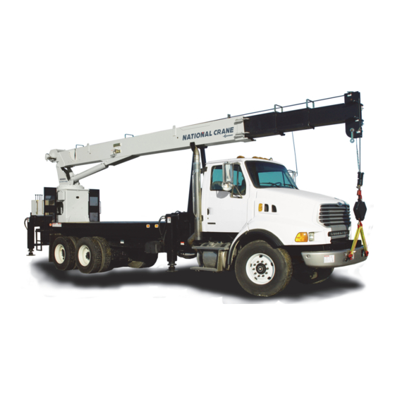
If you are the new owner of a National crane, please register necessary that we reserve the right to make specification it with Manitowoc Crane Care so we have the ability to and equipment changes without notice. contact you if the need arises. - Page 10 INTRODUCTION OPERATOR MANUAL 600H SERIES 600H-Behind the Cab See Figure 1-2 for item number identification. FIGURE 1-1 07-03-19 Control # 091-09...
- Page 11 600H SERIES OPERATOR MANUAL INTRODUCTION 600H-Rear Mount FIGURE 1-2 Item Component Operator Console Operators Station Rated Capacity Limiter (RCL) Reel Boom Item Component Boom Nose Stabilizer Front Outrigger (SFO), Front Outrigger Jack Boom Rest Hydraulic Tank Lift Cylinder RCL Panel Downhaul Weight, Hook Block Boom Angle Indicator Hoist...
- Page 12 Care. The crane must not be returned to service until it is thoroughly inspected for any evidence of damage. All damaged parts must be repaired or replaced as authorized by your local National Crane distributor or Manitowoc Crane Care. 07-03-19 Control # 091-09...
-
Page 13: Safety Messages
600H SERIES OPERATOR MANUAL SAFETY PRECAUTIONS SECTION 2 SAFETY PRECAUTIONS SECTION CONTENTS Safety Messages......2-1 Personnel Handling. -
Page 14: General
National Crane distributor must be immediately advised of the incident and consulted on necessary inspections and repairs. Should the distributor not be immediately available, contact should be made directly with Manitowoc Product Safety at the address below. The equipment must not be CAUTION... -
Page 15: Operator Qualifications
600H SERIES OPERATOR MANUAL SAFETY PRECAUTIONS each person responsible for assembly, disassembly, decals on the equipment. Decals provide important operation and maintenance of the equipment. instructions and warnings and must be read prior to any operational or maintenance function. No personnel shall be allowed to climb onto the equipment or enter the cab or operator’s station unless performance of Refer to the Parts Manual for this equipment for the locations their duties require them to do so, and then only with... -
Page 16: Operational Aids
SAFETY PRECAUTIONS OPERATOR MANUAL 600H SERIES You must be mentally and physically fit to operate • When an Anti-Two-Blocking Device, Two-Blocking equipment. Never attempt to operate equipment while under Damage Prevention Device or Two-Block Warning the influence of medication, narcotics, or alcohol. Any type of Device is inoperative or malfunctioning, the designated drug could impair physical, visual and mental reactions, and person responsible for supervising the lifting operations... -
Page 17: Working Area Limiter (If Equipped)
600H SERIES OPERATOR MANUAL SAFETY PRECAUTIONS Two-blocking occurs when the load block (hook block, the boom is lowered. Keep load handling devices a minimum headache ball, rigging, etc.) comes into physical contact with of 107 cm (42 in) below the boom nose at all times. the boom (boom nose, sheaves, jib, etc.). -
Page 18: Load Charts
SAFETY PRECAUTIONS OPERATOR MANUAL 600H SERIES Load Charts Load Charts represent the absolute maximum allowable loads, which are based on either tipping or structural limitations of the equipment under specific conditions. Knowing the precise load radius, boom length, and boom angle should be a part of your routine planning and operation. -
Page 19: Wind Speeds
600H SERIES OPERATOR MANUAL SAFETY PRECAUTIONS NOTE: The wind speed corresponding to the Beaufort scale in the table is mean wind speed at 10 m (33 ft) elevation over a period of 10 minutes. Table 2-1 Beaufort Wind Scale Maximum Wind Speed Beaufort Visible Indicator Description... - Page 20 SAFETY PRECAUTIONS OPERATOR MANUAL 600H SERIES Simplified Method to Determine Maximum Permissible Wind Speed Determine 3-Second Gust 0.14 V(z) = [(z/10) + 0.4]v [m/s] Wind Speed at boom tip, 0.14 V(z) = [(z/33) + 0.4]v [mph] V(z) 13.4 m/s < V(z) < 20.1 m/s V(z) >...
- Page 21 600H SERIES OPERATOR MANUAL SAFETY PRECAUTIONS Determination of 3-second wind gust speed at boom Size and Shape of the load: tip height: These rated capacities are also based on the assumption that the Wind Resistance Area of load, Awr is not more The following example illustrates how to calculate 3-second (load) wind gust speed at boom tip height based on mean wind...
- Page 22 SAFETY PRECAUTIONS OPERATOR MANUAL 600H SERIES Calculation of Projected Wind Area (Ap) Wind Wind = 8 m = 24 m 25 ft 25 ft Wind Wind 10 ft 3 ft = 75 ft = 250 ft 10 ft 3 ft 8384-1 FIGURE 2-2 Determining Wind Drag Coefficient (Cd)
- Page 23 600H SERIES OPERATOR MANUAL SAFETY PRECAUTIONS Table 2-2 Wind Drag Coefficient Maximum Permissible Wind Speed If the wind resistant area of the load Awr is greater than (load) Shape the allowable wind resistant area Awr , the ratio can be (allow) used to determine a permissible wind speed V(z) for the load 1.1 to 2.0...
- Page 24 SAFETY PRECAUTIONS OPERATOR MANUAL 600H SERIES Rated Load Chart Example - Metric 8383-1 FIGURE 2-3 2-12 07-03-19 Control # 091-09...
- Page 25 600H SERIES OPERATOR MANUAL SAFETY PRECAUTIONS Table 2-4 Example-Capacity Reduction Factors for Wind Speed V(z) Greater than 13.4 m/s - Metric (Only for lifting with main boom on fully extended outriggers, with or without stowed extension) For wind speed V(z) (3-second gust speed at boom tip height) V(z) > 13.4 m/s ≤ 20.1 m/s, the Reduced Capacity shall be calculated by multiplying the Published Rated Capacity by the following factors: Main Boom Length in Meters Wind Speed...
- Page 26 SAFETY PRECAUTIONS OPERATOR MANUAL 600H SERIES At wind speeds greater than 13.4 m/s, it is not permissible to Load example 1.3a: lift a load greater than 12,040 kg, even if the wind resistance With large wind resistance area of the load Awr (load) area of the load is less than 14.45 m •...
- Page 27 600H SERIES OPERATOR MANUAL SAFETY PRECAUTIONS • Is the load to be lifted less than allowable load? Ratio = 1.37 8,000 kg ≤ 12,040 kg • Is Awr less than Awr (load) (allow) From Table 2-5, the maximum permissible wind speed at 19.83 m ≤...
- Page 28 SAFETY PRECAUTIONS OPERATOR MANUAL 600H SERIES Rated Load Chart Example - Non-metric 8382-1 FIGURE 2-4 2-16 07-03-19 Control # 091-09...
- Page 29 600H SERIES OPERATOR MANUAL SAFETY PRECAUTIONS Refer to the above equipment configuration for the following load conditions: Example and Sample Calculations (Non-metric) Load example 2.1: The following example illustrates how to calculate allowable load while operating in wind speed (3-second wind gust With known Wind Drag Coefficient of the load Cd, speed) above 13.4 m/s (30 mph) and maximum permissible •...
-
Page 30: Lifting Operations
SAFETY PRECAUTIONS OPERATOR MANUAL 600H SERIES the wind resistance area of load can be estimated as: • Is Awr less than Awr (load) (allow) 216 ft ≤ 149 ft ......NO = Ap x Cd = 180 x 1.2 = 216 ft (load) Conclusion: This load is NOT permissible to lift in wind... -
Page 31: Counterweight
600H SERIES OPERATOR MANUAL SAFETY PRECAUTIONS Always keep the load as near to the equipment and as close Always use enough parts-of-line to accommodate the load to to the ground as possible. be lifted. Lifting with too few parts-of-line can result in failure of the hoist rope. -
Page 32: Tilt-Up Panel Lifting
SAFETY PRECAUTIONS OPERATOR MANUAL 600H SERIES • Make sure all signals are coordinated through the lift • The total gross load shall not exceed 80% of the director or person in charge of the lift. standard load chart. The operator shall be responsible to control this as the RCL does not have a feature to set •... -
Page 33: Equipment
600H SERIES OPERATOR MANUAL SAFETY PRECAUTIONS • All pile driving and extracting operations shall be showing inspections were performed on the equipment restricted to fully extended outriggers with all tires clear during the time it was used for pile driving or extraction. of the ground. -
Page 34: Set-Up And Operation
SAFETY PRECAUTIONS OPERATOR MANUAL 600H SERIES Example decal. For reference only. 8822 Equipment operation is dangerous when close to an The safest way to avoid electrocution is to stay away from energized electrical power source. Exercise extreme caution electrical power lines and electrical power sources. and prudent judgment. -
Page 35: Electrocution Hazard Devices
600H SERIES OPERATOR MANUAL SAFETY PRECAUTIONS Boom cages and boom guards afford limited protection from electrocution hazards. They are designed to cover only the boom nose and a small portion of the boom. Performance of boom cages and boom guards is limited by their physical size, insulating characteristics, and operating environment (e.g. -
Page 36: Special Operating Conditions And Equipment
Thoroughly inspect the rope and all points of contact on the equipment. Should the distributor not be immediately • Near high-frequency switching stations available, contact Manitowoc Crane Care. The equipment • If a thunder storm is forecast must not be returned to service until it is thoroughly inspected for any evidence of damage and all damaged parts Use electrically conducting material for grounding. - Page 37 600H SERIES OPERATOR MANUAL SAFETY PRECAUTIONS Also see the optional equipment manual titled Personnel • The crane operator must remain at the crane controls at Basket Manual which addresses safety, inspection, testing, all times when personnel are off the ground. operation, installation, and lubrication.
-
Page 38: Environmental Protection
SAFETY PRECAUTIONS OPERATOR MANUAL 600H SERIES • ASME (formerly ANSI) B30 Series American National Follow all applicable safety precautions in this manual when Safety Standards For Cableways, Cranes, Derricks, performing equipment maintenance as well as equipment Hoists, Hooks, Jacks, and Slings; ASME B30.5, Mobile operations. -
Page 39: Lubrication
600H SERIES OPERATOR MANUAL SAFETY PRECAUTIONS for leaks. Wear gloves to protect your hands from • Consult with Manitowoc Crane Care to determine if load spraying fluid. testing is required after a structural repair is performed. • If any hydraulic fluid is injected into the skin, obtain Lubrication medical attention immediately or gangrene may result. -
Page 40: Wire Rope
• Never overload a rope. This means never use the rope NOTE: Rope may be purchased by contacting Manitowoc where the load applied to it is greater than the working Crane Care. load determined by the rope manufacturer. -
Page 41: Sheaves
600H SERIES OPERATOR MANUAL SAFETY PRECAUTIONS Sheaves Environmental factors such as corrosive conditions and heat can damage a wire rope. Lack of lubrication can significantly shorten the useful life of a wire rope. Contact with electrical wires and resulting arcing will damage a wire rope. -
Page 42: Engine
SAFETY PRECAUTIONS OPERATOR MANUAL 600H SERIES • If equipped, disconnect battery with the battery Do not use the dead end lug on the boom nose for tying disconnect switch before disconnecting the ground down the boom during transport. Damage to the lug and battery cable. -
Page 43: Work Practices
Do not make modifications or additions to the equipment’s access system that have not been evaluated and approved Stay alert at the wheel. by Manitowoc Crane Care. If equipped, ensure that the hoist access platform hand rail Do not step on surfaces on the equipment that are not and step are in the travel configuration. -
Page 44: Job Preparation
SAFETY PRECAUTIONS OPERATOR MANUAL 600H SERIES Job Preparation equipment in an area with flammable dust or vapors, unless good ventilation has removed the hazard. Before equipment use: Carbon monoxide fumes from the engine exhaust can cause • Barricade the entire area where the equipment is suffocation in an enclosed area. -
Page 45: Lifting
600H SERIES OPERATOR MANUAL SAFETY PRECAUTIONS Check the hoist brake by raising the load a few inches, stopping the hoist and holding the load. Be sure the hoist brake is working correctly before continuing the lift. When lowering a load always slow down the load’s descent before stopping the hoist. -
Page 46: Hand Signals
SAFETY PRECAUTIONS OPERATOR MANUAL 600H SERIES Be sure everyone is clear of the equipment and work area before making any lifts. Never swing over personnel, regardless of whether load is suspended from or attached to the boom. Hand Signals A single qualified signal person shall be used at all times when: •... - Page 47 600H SERIES OPERATOR MANUAL SAFETY PRECAUTIONS 9580 FIGURE 2-6 National Crane 2-35 07-03-19 Control # 091-09...
-
Page 48: Parking And Securing
SAFETY PRECAUTIONS OPERATOR MANUAL 600H SERIES PARKING AND SECURING • Lock the operator’s cab (if applicable) and install vandal guards, if used. COLD WEATHER OPERATION WARNING Cold weather operation requires additional caution on the Tipping Hazard! part of the operator. When parking the equipment and leaving it unattended Check operating procedures in this manual for cold weather follow the instructions for the Controls and Operating... - Page 49 600H SERIES OPERATOR MANUAL SAFETY PRECAUTIONS would retract approximately 196 mm (7 3/4 in) [see Table 2- cool. The load will lower as the telescope cylinder(s) retracts 8]. A cylinder extended 1.5 m (5 ft) in which the oil cools allowing the boom to come in.
-
Page 50: Overload Inspection
• Stop operating the crane and contact Manitowoc T h e f o l l o w i n g i l l u s t r a t i o n s m a y n o t b e a n e x a c t... -
Page 51: Boom Inspection
600H SERIES OPERATOR MANUAL SAFETY PRECAUTIONS Boom Inspection 9, 10 2, 3 9, 10 Illustration for reference only. Your crane may be different. National Crane 2-39 07-03-19 Control # 091-09... - Page 52 SAFETY PRECAUTIONS OPERATOR MANUAL 600H SERIES NOTE: The following checklist includes all features that can be found on National Cranes. Your crane may not have some features. Overload less than 25% Sheaves, Inspect all for damage. Rope Guides Collar-Wear Pads, Pad Inspect for damage.
-
Page 53: Superstructure Inspection
600H SERIES OPERATOR MANUAL SAFETY PRECAUTIONS Superstructure Inspection 10,11 Illustration for reference only. Your crane may be different. National Crane 2-41 07-03-19 Control # 091-09... - Page 54 SAFETY PRECAUTIONS OPERATOR MANUAL 600H SERIES NOTE: The following checklist includes all features that can be found on National Cranes. Your crane may not have some features. Overload less than 25% Lift Cylinder Inspect for leaking. See topic in Introduction section Wire Rope Inspect all for damage.
-
Page 55: Carrier Inspection
600H SERIES OPERATOR MANUAL SAFETY PRECAUTIONS Carrier Inspection 5, 6 Illustration for reference only. Your crane may be different. National Crane 2-43 07-03-19 Control # 091-09... - Page 56 SAFETY PRECAUTIONS OPERATOR MANUAL 600H SERIES NOTE: The following checklist includes all features that can be found on National Cranes. Your crane may not have some features. Overload less than 25% Jack Cylinders Inspect for leaking. Outrigger Inspect for deformation and cracked welds. Pads Overload from 25% to 49% Jack Cylinders Inspect for leaking.
-
Page 57: Section 3
600H SERIES OPERATOR MANUAL CONTROLS AND OPERATING PROCEDURES SECTION 3 CONTROLS AND OPERATING PROCEDURES SECTION CONTENTS Truck Cab Controls ......3-1 Charging the Battery . -
Page 58: Park Brake
CONTROLS AND OPERATING PROCEDURES OPERATOR MANUAL 600H SERIES Electric Shift Control Full torque electric shift PTO’s are controlled by a switch. To FIGURE 3-1 operate, disengage the clutch, shift to fourth or fifth gear, and operate the switch down to engage the PTO or up to disengage the PTO. -
Page 59: Hoist
600H SERIES OPERATOR MANUAL CONTROLS AND OPERATING PROCEDURES FIGURE 3-2 FRONT Item Description Boom Hoist Telescope Turn Horn Item Description Rear Outrigger Beam Front Outrigger Beam Front Outrigger Jack Outrigger Selector Switch Rear Outrigger Jack Engine Stop Switch Hoist Outriggers Position the control lever to to lower the loadline and The outrigger control is setup so that two like components... -
Page 60: Foot Throttle
CONTROLS AND OPERATING PROCEDURES OPERATOR MANUAL 600H SERIES RCL Power Switch • Outrigger beams extend or retract. • Outrigger jacks are lowered or raised. A toggle switch located in the truck cab powers the RCL for Indicator Independent Outrigger Component Operation Light crane operation. -
Page 61: Equipment Checks
Lubrication section of your crane’s Operator Manual, by contacting your local National Crane distributor, or by • for damaged structural members and welds. contacting Manitowoc Crane Care directly). • all rope guides and cable keepers. • all sheaves for free turning. -
Page 62: Hoist
CONTROLS AND OPERATING PROCEDURES OPERATOR MANUAL 600H SERIES Axles Operating the transmission with a sump temperature below normal operating temperature is limited to: NOTE: For National Crane axle warm-up procedures, refer • operating in the neutral gear or to chassis manufacturer’s manual. •... -
Page 63: Anti-Two-Block Check
600H SERIES OPERATOR MANUAL CONTROLS AND OPERATING PROCEDURES battery(s). Also, if the battery(s) are found to be frozen, do not attempt to charge them. Remove the battery(s) from the DANGER crane, allow them to thaw, and then charge the battery(s) to full capacity. -
Page 64: Working Area
CONTROLS AND OPERATING PROCEDURES OPERATOR MANUAL 600H SERIES WORKING AREA Before Leaving the Truck Cab • Position the truck so that the outriggers can be extended 600 H-BC Working Area with no obstructions. The standard working area for the 600 H-BC is 180° with no •... -
Page 65: Lifting The Load
600H SERIES OPERATOR MANUAL CONTROLS AND OPERATING PROCEDURES • Side Load — Horizontal side force applied to the lifted • The hoist data chart (Figure 3-7) shows hoist capacity load either on the ground or in the air. and multipart line reeving. The correct reeving for all loads listed in the load chart is also shown. -
Page 66: Load Chart
CONTROLS AND OPERATING PROCEDURES OPERATOR MANUAL 600H SERIES Load Chart FIGURE 3-5 3-10 07-03-19 Control # 091-09... -
Page 67: Range Diagram
600H SERIES OPERATOR MANUAL CONTROLS AND OPERATING PROCEDURES Range Diagram FIGURE 3-6 Hoist Data FIGURE 3-7 National Crane 3-11 07-03-19 Control # 091-09... -
Page 68: Shut Down And Preparation For Road Travel
CONTROLS AND OPERATING PROCEDURES OPERATOR MANUAL 600H SERIES SHUT DOWN AND PREPARATION FOR the main boom nose or auxiliary boom nose. The other must be removed and stowed securely before traveling. ROAD TRAVEL If the hook block or downhaul weight remains reeved on the boom, it must be secured at the tie down on the carrier provided for that purpose. -
Page 69: Unattended Crane
600H SERIES OPERATOR MANUAL CONTROLS AND OPERATING PROCEDURES Unattended Crane REMOTE CONTROL The following sections describe the remote control function. For detailed installation and troubleshooting information, see the Service Manual. WARNING Safety Tipping Hazard! Changing weather conditions including but not limited to: wind, ice accumulation, precipitation, flooding, lightning, DANGER etc. -
Page 70: Operation
CONTROLS AND OPERATING PROCEDURES OPERATOR MANUAL 600H SERIES safety switch will not have the start relay installed and 15. Turn Hydraulic Capacity Alert/RCL and Remotes/SLP therefore can not be started with the radio transmitter only. power switches OFF - in truck cab. 16. -
Page 71: Radio Remote Controls
600H SERIES OPERATOR MANUAL CONTROLS AND OPERATING PROCEDURES RADIO REMOTE CONTROLS and stop bits, information concerning the selected switch being activated, and a specialized algorithm developed to The following sections describe the radio remote controls. ensure the validity of the transmission. Also transmitted are For detailed maintenance, installation, and troubleshooting address information to enable it to “talk”... -
Page 72: Emergency Stop Function
CONTROLS AND OPERATING PROCEDURES OPERATOR MANUAL 600H SERIES Emergency Stop Function remote controls. Failure to do so will greatly reduce the life of the 9 volt battery in the hand control (transmitter). This unit is equipped with an Emergency Stop. The transmitter has a momentary push button switch near the antenna. - Page 73 600H SERIES OPERATOR MANUAL CONTROLS AND OPERATING PROCEDURES Question Answer Do you use amplitude modulation (AM) or fre- FM is utilized. FM is a must in electrically noisy environments. These quency modulation (FM)? environments include areas with welders, power lines, industrial machinery, etc.
- Page 74 CONTROLS AND OPERATING PROCEDURES OPERATOR MANUAL 600H SERIES Question Answer How many operations can be done simultane- Two functions can be activated at the same time. However, a single ously? flow control is used to supply both functions. The single flow control allows the function operating at the lower pressure to take priority.
-
Page 75: Section 4
600H SERIES OPERATOR MANUAL SET-UP SECTION 4 SET-UP SECTION CONTENTS Outrigger Setup ......4-1 Stowing Procedure . -
Page 76: Site Selection
SET-UP OPERATOR MANUAL 600H SERIES Site Selection The outrigger floats must be on a firm solid surface that is level. The surface must keep the crane stable and not allow the outrigger float to sink or slide. Avoid areas that are: •... -
Page 77: Jib Safety Information
600H SERIES OPERATOR MANUAL SET-UP 7963-1 FIGURE 4-2 8197-1 JIB SAFETY INFORMATION Ensure jib is stowed correctly (Figure 4-3): Removal of swing around pins, C1, without proper The anti-two-block switch weight and cord must be installation of stow pin A and jib swing pin B, may attached to the jib when deployed. -
Page 78: Side Folding-Swing Around Jib Operation
SET-UP OPERATOR MANUAL 600H SERIES SIDE FOLDING-SWING AROUND JIB Area where jib swings around must be clear of obstructions and power lines when stowing and OPERATION unstowing jib. Deployment Procedure 10. Use safety glasses when pounding pins with hammer. Using boom telescope function, fully retract boom. 11. - Page 79 600H SERIES OPERATOR MANUAL SET-UP JIb in Operating position Stow Pin Jib Swing Pin Jib Deployment Pins Stowage Loop Extension Retaining Pin Jib in Stow Position Stowage Bracket on Jib Index Bar Left Side Right Side FIGURE 4-3 National Crane 07-03-19 Control # 091-09...
-
Page 80: Stowing Procedure
SET-UP OPERATOR MANUAL 600H SERIES 14. Using hoist function, unspool enough loadline to reeve loadline over jib sheave case. Keep slight tension on CAUTION loadline to avoid bird caging of loadline on hoist drum. Use caution during this step. The jib is free to swing away 15. -
Page 81: Jib Removal
600H SERIES OPERATOR MANUAL SET-UP pivot point to swing jib into stow position. A slight hammer strike may be necessary to remove pins. CAUTION Always use proper eye protection during this step. 10. Raise the boom to the horizontal position. The 41 ft (12.49 m) jib weights 960 lbs (435 kg) at 129 in. -
Page 82: Multipart Line Reeving
**The hook block must be sized to the number of line parts. For example, do not use a six part line hook block on a three part line reeving. Contact your National Crane Distributor or Manitowoc Crane Care to order the proper hook block. -
Page 83: Wedge Sockets
600H SERIES OPERATOR MANUAL SET-UP Position the anchor wedge in the drum slot; pull firmly on State and local laws may vary and require different the free end (2) of the cable to secure the wedge. attachment methods depending upon work conditions. The user is responsible for alternate attachment methods. - Page 84 SET-UP OPERATOR MANUAL 600H SERIES strands, caused by the bend around the wedge, to the loop becoming entangled with tree branches and other adjust themselves at the end of the line. Refer to components during crane transport and with the anti-two SECTION 1 - INTRODUCTION in the Service Manual block system and other components during use of the crane.
- Page 85 600H SERIES OPERATOR MANUAL SET-UP Specialty Clip Specialty Wedge Wedge Socket FIGURE 4-8 National Crane 4-11 07-03-19 Control # 091-09...
- Page 86 SET-UP OPERATOR MANUAL 600H SERIES This Page Blank 4-12 07-03-19 Control # 091-09...
-
Page 87: General
For information on • Immediately clean up any spills. extreme condition lubrication, contact your local National Crane distributor or Manitowoc Crane Care. Lubricants Environmental Protection Specific recommendations of brand and grade of lubricants are not made here due to regional availability, operating... -
Page 88: Arctic Lubricants And Conditions
Therefore, always check with an authorized National dry lubrication film which does not attract dust. Lubricant Crane distributor or Manitowoc Crane Care if in doubt of the meets NLGI Class 1-2 specifications. suitability of a specific fluid or lubricant. -
Page 89: Arctic Hydraulic Oil
John Deere Standard JDM J20c. Temperature Down to -9°C (15°F) to -29°C (-20°F) Contact your National Crane distributor or Manitowoc Crane Care if you have any questions. For colder operating conditions, the standard fluid may be... - Page 90 LUBRICATION PROCEDURE AND CHARTS OPERATOR MANUAL 600H SERIES Worn grease fittings that do not hold a grease gun, or those that have a stuck check ball, must be replaced. DANGER When wear pads or rotation bearings are lubricated, cycle Do not, under any circumstances, work at an elevated the components and lubricate again to ensure complete height without using proper fall protection as required by lubrication of the entire wear area.
-
Page 91: Lubrication Chart
600H SERIES OPERATOR MANUAL LUBRICATION PROCEDURE AND CHARTS Lubrication Chart Oil Fill/Breather Oil Drain NOTE: Torque diffuser to 51 lb-ft (69 Nm). Openings must face bottom of tank. Recommended Item Application Procedure Frequency Lubricant Hydraulic oil reservoir HYDO Check fill, change Weekly, semi-annually, as required After first 40 hrs. -
Page 92: Internal Cable Sheave Lubrication
Grease gun Monthly Internal Cable Sheave Lubrication • Contact Manitowoc Crane Care to obtain this tip. Lubrication of the extend and retract sheaves is as follows: Extend the boom until the grease access holes on the DANGER side of the 2 and 3 sections are lined up. -
Page 93: Boom Lubrication Inner Wear Pad
600H SERIES OPERATOR MANUAL LUBRICATION PROCEDURE AND CHARTS Lubricate the pins for the retract sheaves until a small amount of grease extrudes from the sheave pins. From in back of the boom, look up through the hoist mount at the pins to determine the amount of grease. Boom Lubrication Inner Wear Pad Fully extend and set the outriggers on a level surface. -
Page 94: Hoist Brake Oil
LUBRICATION PROCEDURE AND CHARTS OPERATOR MANUAL 600H SERIES Recommended lubricant is EP-3MG grease. Reinstall drain plug and add fluid at the brake oil vent hole until oil is at the bottom level of the inspection hole. Install the Fully extend and set the outriggers. Refer to inspection plug and the oil vent and fill plug. -
Page 95: Swing Gearbox And Brake Oil
Gearbox lubricants are satisfactory for standard operation in temperatures from -23° C to 82° C (-10° F to +180° F). For operation outside this range, contact Manitowoc Crane Care for recommendations. HYDRAULIC OIL RESERVOIR LEVEL... -
Page 96: Carwell© Rust Inhibitor
Protecting Cranes From Corrosion attention should be given to the undercarriage of the crane to minimize the harmful effects of corrosion. Manitowoc Crane Group's cranes are manufactured to high quality standards, including the type of paint finish 5-10 07-03-19 Control # 091-09... -
Page 97: Cleaning Procedures
To help protect against corrosion of National Cranes, Manitowoc Crane Care recommends washing the crane at least monthly to remove all foreign matter. More frequent c l e a n i n g m a y b e n e e d e d w h e n o p e r a t i n g i n h a r s h CAUTION environmental conditions. -
Page 98: Areas Of Application
However, if a crane is used and/or stored in harsh environments (such as islands, coastal regions, industrial Please contact Manitowoc Crane Care should you have any areas, areas where winter road salt is regularly used, etc.), questions. reapplication of Carwell T32-CP-90 is recommended sooner Areas of Application than 12 months, e.g., repeat treatment in 6-9 months. - Page 99 600H SERIES OPERATOR MANUAL LUBRICATION PROCEDURE AND CHARTS 9863 Item Description Mirror Mounting Hardware Item Description Power Train Hardware Hoist Plumbing Connections O/R Hose Connections Pivot Shaft Entire underside of unit Hanger Hardware for Boom Extension Valve Bank, Hose Connections Inside All Hardware, Clips, Pins, Hose Connections Turntable not painted O/R Pins, Clips...
- Page 100 LUBRICATION PROCEDURE AND CHARTS OPERATOR MANUAL 600H SERIES THIS PAGE BLANK 5-14 07-03-19 Control # 091-09...
-
Page 101: Crane Inspection And Maintenance
An inspection log book is DANGER available from your National Crane distributor or Do not, under any circumstances, work at an elevated Manitowoc Crane Care. height without using proper fall protection as required by local, state or federal regulations WARNING... - Page 102 MAINTENANCE CHECKLIST OPERATOR MANUAL 600H SERIES Condition of tires and suspension. Hoist brake for proper operation at Hoist capacity load. Condition of Hoist cable and end attachment for Torque the boom wear pad retaining bolts during first corrosion, severe kinking, crushing, cutting, or slippage month of operation, and monthly thereafter.
-
Page 103: Special Boom Inspection
600H SERIES OPERATOR MANUAL MAINTENANCE CHECKLIST b. Dented barrels • Distortion such as kinking, crushing, un-stranding, bird caging, main strand displacement or core protrusion. Drift from oil leaking by piston • Loss of cable diameter in a short cable length or d. -
Page 104: Care Of Wire Rope
If a cable replacement is required for the boom extension Care of Wire Rope system, the replacement cable must be obtained through the Manitowoc Crane Care. Extension cables are pre-stretched Handle wire rope with care to prevent damage to the and have special connections for proper operation... -
Page 105: Jib Jack Service And Maintenance
600H SERIES OPERATOR MANUAL MAINTENANCE CHECKLIST Jib Jack Service and Maintenance Rust Prevention Important: Use only a good grade hydraulic jack oil, Check the ram every three months for any sign of rust or transmission oil, or turbine oil. Avoid mixing types of oil. Do corrosion. - Page 106 MAINTENANCE CHECKLIST OPERATOR MANUAL 600H SERIES Condition Possible Cause Possible Solution Check PTO ratio, pump size and engine speed Pump not operating at proper speed. for proper oil flow. Low hydraulic fluid supply. Check and fill as required. Relief valve sticking. Remove and clean.
- Page 107 600H SERIES OPERATOR MANUAL MAINTENANCE CHECKLIST Condition Possible Cause Possible Solution Not getting oil to cylinders. Clean and replace as required. Worn or damaged piston seals. Replace as required. Cylinders drift Air in hydraulic oil. Cycle crane cylinder to remove air. Loose holding valve.
-
Page 108: Tire Load And Inflation Table
MAINTENANCE CHECKLIST OPERATOR MANUAL 600H SERIES Tire Load And Inflation Table NOTE: The values in the tables below are as published by the Tire and Rim Association 2005. Your vehicle Definite tire inflation pressures are established for each tire may be equipped with other tire sized or the same size depending upon the load imposed on the tires. - Page 109 600H SERIES OPERATOR MANUAL MAINTENANCE CHECKLIST Radial Ply Metric Tires for Trucks, Busses, and Trailers Used in Normal Highway Service Radial Ply Tires Mounted on 15° Drop Center Rims Tire and Rim Association Standard Radial Ply Metric Tires for Trucks, Busses, and Trailers Used in Normal Highway Service Radial Ply Tires Mounted on 15°...
- Page 110 MAINTENANCE CHECKLIST OPERATOR MANUAL 600H SERIES Metric Wide Base Tires for Trucks, Busses, and Trailers Used in Normal Highway Service Tires Used as Singles Mounted on 15° Drop Center Rims Tire and Rim Association Standard Radial Ply Tires for Trucks, Busses, and Trailers Used in Normal Highway Service Radial Ply Tires Mounted on 15°...
-
Page 111: Specifications
600H SERIES OPERATOR MANUAL MAINTENANCE CHECKLIST SPECIFICATIONS Hydraulic Pump Pump Speed ............... 2500 RPM Displacements: Section P1 ..............18 GPM (68.1 LPM) at 3900 psi +100/-000 (26.89 MPa) Section P2 ..............34 GPM (128.7 LPM) at 3300 psi +100/-000 (22.75 MPa) Section P3 .............. - Page 112 MAINTENANCE CHECKLIST OPERATOR MANUAL 600H SERIES Retract ................50 ±5 sec Boom Extend/Retract Four Section 16 - 49 ft Extend ................45 ±5 sec Retract ................75 ±5 sec Boom Extend/Retract Four Section 27 - 90 ft Extend ................85 ±10 sec Retract ................140 ±10 sec Boom Extend/Retract Four Section 24 - 80 ft Extend ................75 ±10 sec Retract ................125 ±10 sec...
- Page 113 600H OPERATOR MANUAL Alphabetical Index Accidents ............. 2-2 Anti-two-block Weight Installation .
- Page 114 OPERATOR MANUAL 600H THIS PAGE BLANK APL-2...
Need help?
Do you have a question about the National Crane 600H and is the answer not in the manual?
Questions and answers