
Related Manuals for Tolomatic SmartActuator Series


Summary of Contents for Tolomatic SmartActuator Series
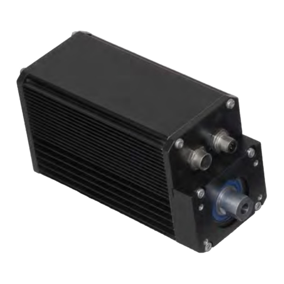
- Page 1 USER GUIDE SmartActuator Series Integrated Control Rod Style Actuator & Motor BASIC ICRSV1 B PLUS ICRSV1P PLUS I CMSV1P 2100-4001_04_ICR_USe LINEAR SOLUTIONS MADE EASY LINEAR SOLUTIONS MADE EASY...
- Page 2 Original Instructions - English Translations will be supplied in other community languages as required by customers Tolomatic reserves the right to change the design or operation of the equipment described herein and any associated motion products without notice. Information in this document is subject to change without notice.
-
Page 3: Table Of Contents
3.1 Cabling and Connectors – ICR/ICM SV1P Plus........3-1 3.1.1 Power Cables and Pin-outs ............3-1 3.1.2 I/O Cables and Pin-outs ..............3-2 3.1.3 Optional Communications Cable ..........3-4 3.2 Digital Inputs – ICR/ICM SV1P Plus ............3-5 Tolomatic User Guide: ICR Rod Style Integrated Control Actuator... - Page 4 5.8.2 Retract Velocity Potentiometer .............5-7 5.8.3 Force Control Potentiometer ............5-7 5.9 User Interface (SV1B Manufactured before 4-2013) ......5-8 5.9.1 Extend Velocity Potentiometer .............5-8 5.9.2 Retract Velocity Potentiometer .............5-9 5.9.3 Force Control Potentiometer ............5-9 Tolomatic User Guide: ICR Rod Style Integrated Control Actuator...
- Page 5 7.6 ICR SV1B Basic and SV1P Plus Rod End and Switch Dimensions ..7-5 7.7 Maintenance and Inspection ..............7-6 7.8 Product Warranty ................7-6 7.9 Troubleshooting ..................7-7 7.9.1 Troubleshooting the ICR SV1B Basic Actuator .......7-7 7.9.2 Troubleshooting the ICR/ICM SV1P Plus ........7-8 Tolomatic User Guide: ICR Rod Style Integrated Control Actuator...
-
Page 6: List Of Figures
ICR/ICM SV1P Plus Logic and Main Power Supplies ....... 3-9 Figure 3-18 ICR/ICM SV1P Plus Single Supply – Main Power ........3-10 Figure 3-19 ICR/ICM SV1P Plus Single Supply – External Cut-off Switch Tolomatic User Guide: ICR Rod Style Integrated Control Actuator... - Page 7 CME 2 Control Panel Features ............6-11 ® Figure 6-13 CME 2 Tool Bar – Scope Tool Location ..........6-11 ® Figure 6-14 CME 2 Scope Tool Screen ..............6-12 ® Tolomatic User Guide: ICR Rod Style Integrated Control Actuator...
-
Page 8: Health And Safety Regulations
Indicates a potentially hazardous situation which, if not avoided, may result in property damage, minor or moderate injury. CAUTION! Indicates hot surfaces. Avoid contact. NOTE! Information that requires special attention is stated here. Tolomatic User Guide: ICR Rod Style Integrated Control Actuator... -
Page 9: Emc Guidelines
It is recommended that the power and signal cables for ICR actuators be routed as far apart as possible to minimize system noise. NOTE! The standard cables from Tolomatic are not flex rated and have a minimum bend radius of 3.75 inches. Any repeated flexing or excessive bending can result in broken conductors and intermittent faults. - Page 10 Since this is an electromechanical device, proper ESD measures should be taken to avoid static electricity from contacting the signal and power lines of the device. viii Tolomatic User Guide: ICR Rod Style Integrated Control Actuator...
-
Page 11: Icr Basic And Icr/Icm Plus Product Overview
ICR Basic and ICR Plus Product Overview 1.1 The ICR SV1B Basic and ICR/ICM SV1P Plus SmartActuators Tolomatic’s ICR rod-style SmartActuators offer all-in-one control with a controller, drive, and motor integrated in one compact easy to use component. Both SV1B Basic and SV1P Plus actuators provide 100% duty cycle for continuous operation. -
Page 12: Sv1P Plus Overview
(127 with CANopen and 63 with DeviceNet) via daisy chain. The RS-232 port can also be used as a gateway to the optional CANopen bus. A Microsoft COM object library is provided to easily utilize the ® Tolomatic User Guide: ICR Rod Style Integrated Control Actuator... -
Page 13: Icr Options
Rod end Options Both the Basic and Plus models offer externally threaded, clevis, rod eye, and alignment coupler rod end options. Tolomatic User Guide: ICR Rod Style Integrated Control Actuator... - Page 14 ICR Plus. All cables are available in either standard or IP65. Starter Kit - ICR Plus Only Tolomatic offers a Starter Kit (Part No. 2180-9100) for use with optional CANopen, USB computer connections and multi-actuator applications. The kit includes: USB to CAN converter (3604-1627)
-
Page 15: Icr Mechanical Specifications
Max Anti-Rotate Performance de-rating will Tolerance degrees ± 0.25 to ± 1.25 be necessary at ambient temperatures greater than 77° RoHS RoHs Compliant Components COMPLIANT F (25° C). RoHS Approval Pending COMPLIANT Tolomatic User Guide: ICR Rod Style Integrated Control Actuator... -
Page 16: Icr Speed And Thrust Curves
NOTe: ICR rod-style SmartActuators are designed to push guided and supported loads and are not designed for applications that require significant side loading. Please contact Tolomatic at 1-800-328-2174 or 763-478-8000 for details regarding side loading capabilities. BN05... -
Page 17: Rms Thrust And Velocity Considerations
25,400 1,000,000 25,400 2,540 2,540 100,000 100,000 10,000 10,000 BN02 BN02 1,000 25.4 1,000 25.4 2.54 2.54 .254 .254 BN05 BN05 THRUST (lbf) THRUST (lbf) Figure 1-3: ICR Ball Screw Life Tolomatic User Guide: ICR Rod Style Integrated Control Actuator... -
Page 18: Icr System Critical Speed
STROKE (in) 1.1.9 ICR Side Load Considerations Rod screw actuators are designed to push guided and supported loads and are not designed for applications that require significant side loading. Contact Tolomatic for details regarding side loading capabilities. 1.1.10 Brake Considerations An unpowered ICR will require a brake to maintain its position if the force on the actuator exceeds: BN02 screw - 7.5 lbf (33.4 N);... -
Page 19: Icr Sv1B Basic - Electrical Interface, Specs & Wiring
3604-1649 Amphenol: PT02E12-3P(027) Amphenol: PT06E12-3S(476) Socket contacts: Std. Conec: 131C10029X Conec: 132C10029X * This type of mating connection is used on Tolomatic supplied cables. Reference this type of mating connector for customer designed cables. PIN NUMBeRS STd. IP65 deSCRIPTION CABLe WIRe COLOR... -
Page 20: I/O Cables And Pin-Outs
Norcomp: 171-025-103L001 Norcomp: 171-025-203L001 I/O: IP65, 5 meter 3604-1648 Amphenol: PT02E16-26P(027) Amphenol: PT06E16-26S(476) * This type of mating connection is used on Tolomatic supplied cables. Reference this type of mating connector for customer designed cables. PIN NUMBeRS TeCHNICAL INFO. STd. IP65... -
Page 21: Figure 2-3 Icr Sv1B Basic Actuator Standard I/O Cable 3604-1640
AMPHENOL P/N: 171-009-203L001 AMPHENOL P/N: 97-79-513-8 171-009-203L001 PTO6E16-26S(476) 979-009-030R121 PTO6E16-26S(476) 979-009-030R121 RED/BLK/WHT ORG/GRN CAROL P/N CØ748A [ 101.6 ] 4.00 [5.0 M] Figure 2-4: ICR SV1B Basic Actuator IP65 I/O Cable 3604-1648 Tolomatic User Guide: ICR Rod Style Integrated Control Actuator... -
Page 22: Cable Routing
All of the digital inputs have a common return. Figure 2-6 shows the circuit diagram for the interface. INPUT 4.7K TO INTERNAL CIRCUITRY INPUT COMMON Figure 2-6: ICR SV1B Basic Actuator Interface Circuit Diagram Tolomatic User Guide: ICR Rod Style Integrated Control Actuator... -
Page 23: Typical Wiring Connections
Emergency stop. Removal of this signal will disable the drive and engage the brake if installed. The remaining spare inputs and any designated inputs can be programmed at Tolomatic for custom applications. Please consult Tolomatic for custom applications. 2.2.1. Typical Wiring Connections INPUT... -
Page 24: Figure 2-8 Icr Sv1B Basic Actuator Input Source (Pnp) Connection
INPUT COMMON 24V POWER SUPPLY INPUT Figure 2-9: ICR SV1B Basic Actuator Input Sink (switched) Connection INPUT COMMON 24V POWER SUPPLY INPUT Figure 2-10: ICR SV1B Basic Actuator Input Sink (NPN) Connection Tolomatic User Guide: ICR Rod Style Integrated Control Actuator... -
Page 25: Digital Outputs - Icr Sv1B Basic Actuator
Output will go high when the actuator is not moving. Fault Output will go high when an error is present. The spare and any designated outputs can be programmed at Tolomatic for custom applications. Please consult Tolomatic for custom applications. Tolomatic User Guide: ICR Rod Style Integrated Control Actuator... -
Page 26: Optional Electronic Brake - Icr Sv1B Basic Actuator
2 : I C R S V 1 B B A S I C - E L E C T R I C A L I N T E R F A C E , S P E C S & W I R I N G 2.4 Optional electronic Brake – ICR SV1B Basic Actuator Tolomatic offers an optional spring-applied, electronically-released brake that can be used with the actuator to keep the actuator from back driving, typically in vertical CAUTION! applications. -
Page 27: Input Power - Icr Sv1B Basic Actuator
KEEP ALIVE FUSE +24-48VDC POWER 24 to 48VDC 24 to 48VDC HIGH POWER POWER SUPPLY POWER GROUND CASE / SHIELD GROUND Figure 2-13: ICR SV1B Basic Actuator Logic and Main Power Supplies Tolomatic User Guide: ICR Rod Style Integrated Control Actuator... -
Page 28: Figure 2-14 Icr Sv1B Basic Actuator Single Supply - Main Power
KEEP ALIVE 24 to 48VDC HIGH POWER POWER SUPPLY POWER GROUND CASE / SHIELD GROUND Figure 2-15: ICR SV1B Basic Actuator Single Supply - External Cut-off Switch for Emergency Stop 2-10 Tolomatic User Guide: ICR Rod Style Integrated Control Actuator... -
Page 29: Environmental Conditions
24V to Power Switch Std.: 3604-1640 IP65: 3604-1648 Logic Device Signals Actuator and Sensing Power Cable (To Power Source) Devices Std.: 3604-1641 IP65: 3604-1649 Figure 2-16: ICR SV1B Basic Actuator Setup Tolomatic User Guide: ICR Rod Style Integrated Control Actuator 2-11... - Page 30 2 : I C R S V 1 B B A S I C - E L E C T R I C A L I N T E R F A C E , S P E C S & W I R I N G (This page intentionally left blank) 2-12 Tolomatic User Guide: ICR Rod Style Integrated Control Actuator...
-
Page 31: Icr/Icm Sv1P Plus - Electrical Interface, Specs & Wiring
3604-1649 Amphenol: PT02E12-3P(027) Amphenol: PT06E12-3S(476) Socket contacts: Std. Conec: 131C10029X Conec: 132C10029X * This type of mating connection is used on Tolomatic supplied cables. Reference this type of mating connector for customer designed cables. PIN NUMBeRS STd. IP65 deSCRIPTION CABLe WIRe COLOR... -
Page 32: I/O Cables And Pin-Outs
Norcomp: 171-025-103L001 Norcomp: 171-025-203L001 I/O: IP65, 5 meter 3604-1648 Amphenol: PT02E16-26P(027) Amphenol: PT06E16-26S(476) * This type of mating connection is used on Tolomatic supplied cables. Reference this type of mating connector for customer designed cables. PIN NUMBeRS STd. IP65 deSCRIPTION... -
Page 33: Figure 3-3 Icr/Icm Sv1P Plus Standard I/O Cable 3604-1640
AMPHENOL P/N: 171-009-203L001 AMPHENOL P/N: 97-79-513-8 171-009-203L001 PTO6E16-26S(476) 979-009-030R121 PTO6E16-26S(476) 979-009-030R121 RED/BLK/WHT ORG/GRN CAROL P/N CØ748A [ 101.6 ] 4.00 [5.0 M] Figure 3-4: ICR/ICM SV1P Plus IP65 I/O Cable 3604-1648 Tolomatic User Guide: ICR Rod Style Integrated Control Actuator... -
Page 34: Optional Communications Cable
1 - Drain, Shield 4 - White, CAN High 2 - Red, V+ 5 - Blue, CAN Lo 3 - Black, V- (CAN Ground) 4 - White, CAN High 5 - Blue, CAN Lo Tolomatic User Guide: ICR Rod Style Integrated Control Actuator... -
Page 35: Digital Inputs - Icr/Icm Sv1P Plus
E-stop Positive Going Threshold 3.5 Vdc hardware measure to Negative Going Threshold 0.9 Vdc ensure safety. Nominal Input Impedance (24V) 4.8K Ohm Off State Current (maximum) 0.4 mA Input Filter 100ns Tolomatic User Guide: ICR Rod Style Integrated Control Actuator... -
Page 36: Typical Wiring Connections
Figure 3-9: ICR/ICM SV1P Plus Source (PNP) Connection INPUT COMMON 24V POWER SUPPLY INPUT Figure 3-10: ICR/ICM SV1P Plus Sink (switched) Connection INPUT COMMON 24V POWER SUPPLY INPUT Figure 3-11: ICR/ICM SV1P Plus Sink (NPN) Connection Tolomatic User Guide: ICR Rod Style Integrated Control Actuator... -
Page 37: Analog Inputs - Icr/Icm Sv1P Plus
Output low maximum (20 mA sink) Maximum continuous current 20 mA Fold back current 80 mA Maximum output sink / source voltage 24 V Update rate 1 ms Output Leakage Current 10 uA Tolomatic User Guide: ICR Rod Style Integrated Control Actuator... -
Page 38: Figure 3-14 Icr/Icm Sv1P Plus Digital Output Circuitry
OUTPUT+ 24V POWER SUPPLY OUTPUT- Figure 3-15: ICR/ICM SV1P Plus Digital Output Sinking Wiring Diagram OUTPUT- OUTPUT+ 24V POWER SUPPLY LOAD Figure 3-16: ICR/ICM SV1P Plus Digital Output Sourcing Wiring Diagram Tolomatic User Guide: ICR Rod Style Integrated Control Actuator... -
Page 39: Input Power - Icr/Icm Sv1P Plus
KEEP ALIVE FUSE +24-48VDC POWER 24 to 48VDC 24 to 48VDC HIGH POWER POWER SUPPLY POWER GROUND CASE / SHIELD GROUND Figure 3-17: ICR/ICM SV1P Plus Logic and Main Power Supplies Tolomatic User Guide: ICR Rod Style Integrated Control Actuator... -
Page 40: Figure 3-18 Icr/Icm Sv1P Plus Single Supply - Main Power
FUSE KEEP ALIVE 24 to 48VDC HIGH POWER POWER SUPPLY POWER GROUND CASE / SHIELD GROUND Figure 3-19: ICR/ICM SV1P Plus Single Supply - External Cutoff Switch for Emergency Stop 3-10 Tolomatic User Guide: ICR Rod Style Integrated Control Actuator... -
Page 41: Optional Electronic Brake - Icr/Icm Sv1P Plus
I C R / I C M S V 1 P P L U S - E L E C T R I C A L I N T E R F A C E , S P E C S & W I R I N G 3.6 Optional electronic Brake – ICR/ICM SV1P Plus Tolomatic offers an optional spring-applied, electronically-released brake that can be used with the actuator to keep the actuator from back driving, typically in vertical CAUTION! applications. -
Page 42: Icr/Icm Plus Setup
Before installing the actuator as a CAN node, use the CME 2 software for setup ® and configuration. The software is furnished on the CD shipped with the Tolomatic Single Actuator Setup for CANopen Position Control software from the Tolomatic web ICR actuator. -
Page 43: Figure 3-22 Icr/Icm Sv1P Plus Multi-Drop Rs-232 Setup (Rs-232 To Optional Canopen)
Male: 3604-1653 CAN addresses in network Female: 3604-1654 • Last and first actuator must have 120 Ω terminating resistor Figure 3-22: ICR/ICM SV1P Plus Multi-drop RS-232 Setup (RS-232 to optional CANopen) Tolomatic User Guide: ICR Rod Style Integrated Control Actuator 3-13... -
Page 44: Multiple Device Setup For Optional Canopen And Devicenet
77˚ F, 25˚ C Nominal Operating Temperature 50-122˚ F, 10-50˚ C [de-rate performance above 77˚ F (25˚ C) ] Storage Temperature 50-158˚ F, 10-70˚ C Humidity 0-95% non-condensing IP Rating 40 standard, 65 optional 3-14 Tolomatic User Guide: ICR Rod Style Integrated Control Actuator... -
Page 45: Power Supply Recommendations
The shunt regulator The actuator emergency available from Tolomatic (see page 4-4) has the appropriate bus capacitance, stop function should requiring only the use of a blocking diode. -
Page 46: System Power Overloading Considerations
Screw terminals are marked with “+” and “-” and should be connected to the regulated bus (see page 4-4). LOAD (N) 1112 BN02 BN02 BN05 BN05 LOAD (lb) Figure 4-1: Maximum Load/Velocity of System without a Voltage Control Device Tolomatic User Guide: ICR Rod Style Integrated Control Actuator... -
Page 47: Suggested Power Supplies
KEEP ALIVE DIODE E-STOP FUSE +24-48VDC POWER 24 to 48VDC SHUNT REGULATED REGULATOR POWER SUPPLY POWER GROUND CASE / SHIELD GROUND Figure 4-4: Regulated Power Supply with Blocking Diode and Shunt Regulator Tolomatic User Guide: ICR Rod Style Integrated Control Actuator... -
Page 48: Shunt Regulators
1.5X peak current rating of the application. ANODE CATHODE TO SHUNT REGULATOR AND ACTUATOR (+) 24 to 48VDC HIGH POWER POWER SUPPLY TO SHUNT REGULATOR AND ACTUATOR (-) Figure 4-6: Diode Wiring Diagram Tolomatic User Guide: ICR Rod Style Integrated Control Actuator... -
Page 49: How To Use The Icr Sv1B Basic Actuator
Actuator holds its position without backdriving Enable command is deactivated Actuator is free to backdrive unless an electronic brake option is installed Figure 5-1: ICR SV1B Basic Actuator enable Input Command Tolomatic User Guide: ICR Rod Style Integrated Control Actuator... -
Page 50: Home Position
5 turn per inch ball screw: 22.2 in/sec Actuator Receives First Input Command TO POWER SOURCE Actuator moves into the Retract Hard-stop Position Actuator moves into the HOME Position Figure 5-2: ICR SV1B Basic Actuator Home Position Tolomatic User Guide: ICR Rod Style Integrated Control Actuator... -
Page 51: Extend Input Command
Activating a Retract input command during rod extension will bring the actuator to a stop, hold its position and activate a Fault output signal. Figure 5-3: ICR SV1B Basic Actuator extend Input Command Tolomatic User Guide: ICR Rod Style Integrated Control Actuator... -
Page 52: Retract Input Command
Activating an Extend input command during rod retract will bring the actuator to a stop, hold its position and activate a Fault output signal. Figure 5-4: ICR SV1B Basic Actuator Retract Input Command Tolomatic User Guide: ICR Rod Style Integrated Control Actuator... -
Page 53: E-Stop Input
When the motion is complete, the In-Position output is turned on. ICR SV1B Basic Actuator In-Position Window definitions SCReW deSCRIPTION IN-POSITION WINdOW 2 turn per inch ball screw .0125” (.317 mm) 5 turn per inch ball screw .005” (.127 mm) Tolomatic User Guide: ICR Rod Style Integrated Control Actuator... -
Page 54: User Interface
Turn the potentiometer screw clockwise to increase the actuator’s rod Extend velocity and counter-clockwise to decrease the Extend velocity. Figure 5-6: ICR SV1B Basic Actuator extend Velocity Potentiometer Tolomatic User Guide: ICR Rod Style Integrated Control Actuator... -
Page 55: Retract Velocity Potentiometer
Push force for locating is best used under low velocity [less than 3"/sec. (76mm/sec.) conditions to give the actuator time to react. recommended] Figure 5-8: ICR SV1B Basic Actuator Force Control Potentiometer Tolomatic User Guide: ICR Rod Style Integrated Control Actuator... -
Page 56: User Interface (Sv1B Manufactured Before 4-2013)
Turn the potentiometer screw clockwise to increase the actuator’s rod Extend velocity and counter-clockwise to decrease the Extend velocity. Figure 5-10: ICR SV1B Basic Actuator extend Velocity Potentiometer Tolomatic User Guide: ICR Rod Style Integrated Control Actuator... -
Page 57: Retract Velocity Potentiometer
Push force for locating is best used under low velocity [less than 3"/sec. (76mm/sec.) conditions to give the actuator time to react. recommended] Figure 5-12: ICR SV1B Basic Actuator Force Control Potentiometer Tolomatic User Guide: ICR Rod Style Integrated Control Actuator... - Page 58 5 : H O W T O U S E T H E I C R S V 1 B B A S I C A C T U A T O R (This page intentionally left blank) 5-10 Tolomatic User Guide: ICR Rod Style Integrated Control Actuator...
-
Page 59: How To Use The Icr/Icm Sv1P Plus
References to software programs and manuals are provided where applicable and are on the Tolomatic CD-ROM that shipped with the actuator. The manuals and software are also available online. Web addresses are provided where appropriate throughout this section. -
Page 60: Software
6. Extract the contents of the .zip file to the same location. The folder should contain the Setup.exe file. Run the setup.exe file. 6.2.2 Cd-ROM Install 1. Insert the Tolomatic CD-ROM supplied with the ICR Plus actuator. Inserting the CD will cause the installation script to launch and a CME 2 installation screen ®... -
Page 61: Configure Serial Port Parameters (Rs-232 And Devicenet)
1. Select Serial Port as the device (see Figure 6-2) in the Communications Wizard (Tools/Communication Wizard) and click the Next button to open the Communications Wizard Select Serial Ports screen. Figure 6-3: Communication Wizard Serial Port Screen Tolomatic User Guide: ICR Rod Style Integrated Control Actuator... -
Page 62: Configure Can Network Parameters
CAN Network settings. 1. In the Communications Wizard Device Selection screen select CAN Network. Click Next to open the Communications Wizard Configure CAN Network screen. Figure 6-5: Communication Wizard Configure CAN Network Screen Tolomatic User Guide: ICR Rod Style Integrated Control Actuator... -
Page 63: Cme 2 ® User Interface And Tool Bar
Not required because the ICR actuator is pre-set at Auto Phase Icon Tolomatic. Not required because the ICR actuator is pre-tuned Auto Tune Icon at Tolomatic. Scope Icon Opens the Scope window. Tolomatic User Guide: ICR Rod Style Integrated Control Actuator... -
Page 64: Icr/Icm Sv1P Plus Amplifier Files
6.7.1 Loading the Amplifier Files The amplifier file (*.ccx) for the ICR/ICM SV1P Plus actuator is configured and loaded by Tolomatic at the factory. The amplifier file contains setup, motor, and tuning information allowing the actuator to operate once it is powered. The default mode of operation is in a position mode via a program. -
Page 65: Command Sources
For complete information on programming, functions, ASCII commands over serial, homing and loading configurations from files using the indexer program, refer to the Indexer 2 Program User Guide (Indexer_user_guide.pdf) on the Tolomatic CD-ROM that shipped with the ICR Plus actuator. -
Page 66: Analog Command
The encoder on the ICR Plus is not exposed through the connectors and requires a factory modification in order to utilize the current and velocity mode scaling parameters. Contact Tolomatic if current or velocity modes of operation are required. -
Page 67: Digital Input Command
Appendix G: ASCII Commands/Serial Control of the CME2_User_Guide.pdf provided on the CD-ROM shipped with the ICR Plus actuator. For constructing ASCII strings to send serially, refer to ASCII_ProgrammersGuide.pdf contained on the same CD-ROM. Tolomatic User Guide: ICR Rod Style Integrated Control Actuator... -
Page 68: Diagnostics
Use this diagnostic tool to quickly check faults, monitor position, enable/disable, and initiate simple moves. To access the Control Panel, click on the Control Panel icon in the tool bar. Figure 6-11: CME 2 Tool Bar - Control Panel Location ® 6-10 Tolomatic User Guide: ICR Rod Style Integrated Control Actuator... -
Page 69: Scope Tool
To access the Scope Tool, click on the Scope Tool icon located on the CME 2 Tool ® Bar. Figure 6-13: CME 2 Tool Bar - Scope Tool Location ® Tolomatic User Guide: ICR Rod Style Integrated Control Actuator 6-11... -
Page 70: Figure 6-14 Cme 2 ® Scope Tool Screen
Section 15: Scope Tool on the CME 2 User Guide provided on the CD-ROM shipped with the ICR Plus ® actuator. 6-12 Tolomatic User Guide: ICR Rod Style Integrated Control Actuator... -
Page 71: Appendix
0.59 Option STROKE [15.0] STROKE BN05 0.77 11.63 [19.5] [295.4] STROKE 1.75 7.31 [44.5] [185.8] 6.31 [160.3] 0.28 [7.1] 3.14 [79.8] 2.09 [53.1] 0.50 [12.7] 3.94 [100.0] 0.51 [12.9] 1.56 [39.5] Tolomatic User Guide: ICR Rod Style Integrated Control Actuator... -
Page 72: Icr_Rp Sv1B Basic And Sv1P Plus Actuator Dimensions
It does NOT have 9.38 [238.3] 1.22 2.09 [53.0] 2.07 [31.1] 0.53 a NeMA or IeC [52.6] [13.5] 0.50 standard mount. [12.6] 1.22 [31.1] 1.03 0.51 [26.2] [12.9] 1.56 1.03 [39.5] [26.2] Tolomatic User Guide: ICR Rod Style Integrated Control Actuator... -
Page 73: Icr_Lmi Sv1B Basic And Sv1P Plus Options Dimensions
1.22 3.39 [31.1] 4.05 4.00 2.63 [86.0] [101.6] [102.8] [66.7] 1.03 [26.2] 1.03 MOUNTING [26.2] Ø.4717 11.981 PLATE 0.45 H M 2 0.4728 12.009 TUBE CLAMP [11.5] 1.00 1.00 [25.4] [25.4] Tolomatic User Guide: ICR Rod Style Integrated Control Actuator... -
Page 74: Icr_Rp Sv1B Basic And Sv1P Plus Options Dimensions
REAR CLEVIS MOUNT P C D 11.99 Ø .472 1.240 11.96 .471 [31.50] 3.14 1.98 [79.9] [50.3] 1.10 [28.0] TRUNNION 0.47 12.70 .500 [11.9] MOUNT Ø T R N 12.65 .498 Tolomatic User Guide: ICR Rod Style Integrated Control Actuator... -
Page 75: Icr Sv1B Basic And Sv1P Plus Rod End And Switch Dimensions
.31 [8] .51 [13] 197 [5000] 1.10 [27.9] K - QD (Quick-disconnect) switch M8x1 1.18 [30] 13.35 [339] 8100-9180 - QD Cable 1.26 [32.1] M8x1 .95 [24.1] Ø.35 Ø.28 [7] 197 [5000] Tolomatic User Guide: ICR Rod Style Integrated Control Actuator... -
Page 76: Maintenance And Inspection
Tolomatic. If, within this period, any product is proven to be defective by Tolomatic, the product will either be repaired or replaced at Tolomatic’s option. -
Page 77: Troubleshooting
1. Determine if there is regenerative energy. 2. Determine if push force is set too low. 3. Determine if power supply has enough current. 4. Check for irregularities in the load. Tolomatic User Guide: ICR Rod Style Integrated Control Actuator... -
Page 78: Troubleshooting The Icr/Icm Sv1P Plus
1. Determine if there is regenerative energy. 2. Current limit is set too low. 3. Following error is set too low. 4. Determine if power supply has enough current. 5. Check for irregularities in the load. Tolomatic User Guide: ICR Rod Style Integrated Control Actuator... - Page 79 Copyright © 2015 Tolomatic, Inc. All rights Reserved. CME 2 is a registered trademark of Copley Controls Incorporated. ® All brand and product names are trademarks of their respective owners. Information in this document is believed to be accurate at time of publication.
- Page 80 3800 County Road 116, Hamel, MN 55340 Phone: 763.478.8000 Toll Free: 1.800.328.2174 Fax: 763.478.8080 Email: help@tolomatic.com www.tolomatic.com...
Need help?
Do you have a question about the SmartActuator Series and is the answer not in the manual?
Questions and answers