Sign In
Upload
Manuals
Brands
Tolomatic Manuals
Controller
SmartActuator ICMSV1P PLUS
Tolomatic SmartActuator ICMSV1P PLUS Manuals
Manuals and User Guides for Tolomatic SmartActuator ICMSV1P PLUS. We have
1
Tolomatic SmartActuator ICMSV1P PLUS manual available for free PDF download: User Manual
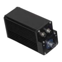
Tolomatic SmartActuator ICMSV1P PLUS User Manual (80 pages)
Integrated Control Rod Style Actuator & Motor
Brand:
Tolomatic
| Category:
Controller
| Size: 5 MB
Table of Contents
Table of Contents
3
List of Figures
6
Health and Safety Regulations
8
EMC Guidelines
9
Proper and Safe Use of Product
9
1 ICR Basic and ICR/ICM Plus Product Overview
11
SV1B Basic Overview
11
SV1P Plus Overview
12
ICR Options
13
ICR Mechanical Specifications
15
ICR Speed and Thrust Curves
16
Figure 1-1 BN05 Ball Nut: Continuous and Peak Speed Vs Thrust
16
Figure 1-2 BN02 Ball Nut: Continuous and Peak Speed Vs Thrust
16
RMS Thrust and Velocity Considerations
17
ICR Screw Life
17
Figure 1-3 ICR Ball Screw Life
17
ICR System Critical Speed
18
Side Load Considerations
18
Brake Considerations
18
ICM Plus Mechanical Specs
18
ICM Plus Motor Speed Vs Torque
18
Figure 1-4 ICR System Critical Speed
18
Figure 1-5 ICM Plus Motor Speed Vs Torque
18
2 ICR SV1B Basic - Electrical Interface, Specs & Wiring
19
Cabling and Connectors - ICR SV1B Basic Actuator
19
Power Cables and Pin-Outs
19
Figure 2-1 ICR SV1B Basic Actuator Standard Power Cable 3604-1641
19
Figure 2-2 ICR SV1B Basic Actuator IP65 Power Cable 3604-1649
19
I/O Cables and Pin-Outs
20
Figure 2-3 ICR SV1B Basic Actuator Standard I/O Cable 3604-1640
21
Figure 2-4 ICR SV1B Basic Actuator IP65 I/O Cable 3604-1648
21
Cable Routing
22
Digital Inputs - ICR SV1B Basic Actuator
22
Figure 2-5 Cable Routing for Top and Side Mounted Connectors
22
Figure 2-6 ICR SV1B Basic Actuator Interface Circuit Diagram
22
Figure 2-7 ICR SV1B Basic Actuator Input Source (Switched) Connection
23
Typical Wiring Connections
23
Figure 2-10 ICR SV1B Basic Actuator Input Sink (NPN) Connection
24
Figure 2-8 ICR SV1B Basic Actuator Input Source (PNP) Connection
24
Figure 2-9 ICR SV1B Basic Actuator Input Sink (Switched) Connection
24
Digital Outputs - ICR SV1B Basic Actuator
25
Figure 2-11 ICR SV1B Basic Actuator Output Interface Circuit Diagram
25
Optional Electronic Brake - ICR SV1B Basic Actuator
26
Figure 2-12 ICR SV1B Basic Actuator Optional Electronic Brake Connection
26
Input Power - ICR SV1B Basic Actuator
27
Figure 2-13 ICR SV1B Basic Actuator Logic and Main Power Supplies
27
Figure 2-14 ICR SV1B Basic Actuator Single Supply - Main Power
28
Figure 2-15 ICR SV1B Basic Actuator Single Supply - External Cut-Off Switch for Emergency Stop
28
Environmental Conditions
29
ICR SV1B Basic Actuator Setup
29
Figure 2-16 ICR SV1B Basic Actuator Setup
29
3 ICR/ICM SV1P Plus - Electrical Interface, Specs & Wiring
31
Cabling and Connectors - ICR/ICM SV1P Plus
31
Power Cables and Pin-Outs
31
Figure 3-1 ICR/ICM SV1P Plus Standard Power Cable 3604-1641
31
Figure 3-2 ICR/ICM SV1P Plus IP65 Power Cable 3604-1649
31
I/O Cables and Pin-Outs
32
Figure 3-3 ICR/ICM SV1P Plus Standard I/O Cable 3604-1640
33
Figure 3-4 ICR/ICM SV1P Plus IP65 I/O Cable 3604-1648
33
Optional Communications Cable
34
Figure 3-5 ICR/ICM SV1P Plus Optional Communications Cable
34
Digital Inputs - ICR/ICM SV1P Plus
35
Isolated Digital Inputs
35
High Speed Digital Inputs
35
Figure 3-6 ICR/ICM SV1P Plus Isolated Interface Circuit Diagram
35
Typical Wiring Connections
36
Figure 3-7 ICR/ICM SV1P Plus High Speed Digital Input Circuitry
36
Figure 3-8 ICR/ICM SV1P Plus Source (Switched) Connection
36
Figure 3-9 ICR/ICM SV1P Plus Source (PNP) Connection
36
Figure 3-10 ICR/ICM SV1P Plus Sink (Switched) Connection
36
Figure 3-11 ICR/ICM SV1P Plus Sink (NPN) Connection
36
Analog Inputs - ICR/ICM SV1P Plus
37
Digital Outputs - ICR/ICM SV1P Plus
37
Figure 3-12 ICR/ICM SV1P Plus Analog Input Circuit
37
Figure 3-13 ICR/ICM SV1P Plus Analog Input Typical Wiring
37
Figure 3-14 ICR/ICM SV1P Plus Digital Output Circuitry
38
Figure 3-15 ICR/ICM SV1P Plus Digital Output Sinking Wiring Diagram
38
Figure 3-16 ICR/ICM SV1P Plus Digital Output Sourcing Wiring Diagram
38
Input Power - ICR/ICM SV1P Plus
39
Figure 3-17 ICR/ICM SV1P Plus Logic and Main Power Supplies
39
Figure 3-18 ICR/ICM SV1P Plus Single Supply - Main Power
40
Figure 3-19 ICR/ICM SV1P Plus Single Supply - External Cut-Off Switch
40
Optional Electronic Brake - ICR/ICM SV1P Plus
41
Figure 3-20 ICR/ICM SV1P Plus Optional Electronic Brake Connection
41
ICR/ICM Plus Setup
42
Single Device Setup for Optional Canopen Position Control
42
Multi-Drop RS-232 (RS-232 to Optional Canopen) Setup
42
Figure 3-22 ICR/ICM SV1P Plus Multi-Drop RS-232 Setup (RS-232 to Optional Canopen)
43
Multiple Device Setup for Optional Canopen and Devicenet
44
Environmental Conditions
44
4 Power Supply Recommendations
45
Regulated and Unregulated Power Supplies
45
Power Supply Sizing Guidelines
45
System Power Overloading Considerations
46
Figure 4-1 Maximum Load/Velocity of System Without a Voltage Control Device
46
Suggested Power Supplies
47
Figure 4-2 Unregulated Power Supply Configuration with Shunt Regulator
47
Figure 4-3 Regulated Power Supply Configuration with Blocking Diode and Added Capacitance
47
Figure 4-4 Regulated Power Supply with Blocking Diode and Shunt Regulator
47
Shunt Regulators
48
Diodes
48
Figure 4-5 Shunt Regulator Input Wiring Diagram
48
Figure 4-6 Diode Wiring Diagram
48
5 How to Use the ICR SV1B Basic Actuator
49
Enable Input Command
49
Figure 5-1 ICR SV1B Basic Actuator Enable Input Command
49
Home Position
50
Figure 5-2 ICR SV1B Basic Actuator Home Position
50
Extend Input Command
51
Figure 5-3 ICR SV1B Basic Actuator Extend Input Command
51
Retract Input Command
52
Figure 5-4 ICR SV1B Basic Actuator Retract Input Command
52
E-Stop Input
53
Fault Output
53
In-Position Output
53
User Interface
54
Extend Velocity Potentiometer
54
Figure 5-5 ICR SV1B Basic Actuator Velocity and Force Controls
54
Figure 5-6 ICR SV1B Basic Actuator Extend Velocity Potentiometer
54
Retract Velocity Potentiometer
55
Force Control Potentiometer
55
Figure 5-7 ICR SV1B Basic Actuator Retract Velocity Potentiometer
55
Figure 5-8 ICR SV1B Basic Actuator Force Control Potentiometer
55
User Interface (SV1B Manufactured before 4-2013)
56
Extend Velocity Potentiometer
56
Retract Velocity Potentiometer
57
Force Control Potentiometer
57
6 How to Use the ICR/ICM SV1P Plus
59
Host Computer Requirements
59
Hardware Requirements
59
Operating Systems Supported
59
Software
60
Install the CME 2 ® Software
60
Web Download Install
60
CD-ROM Install
60
Start the CME 2 ® Software
60
Initial Communication Setup
60
Figure 6-1 Copley Motion Explorer CME
60
Configure Serial Port Parameters (RS-232 and Devicenet)
61
Figure 6-2 Communication Wizard Device Selection Screen
61
Figure 6-3 Communication Wizard Serial Port Screen
61
Configure CAN Network Parameters
62
Figure 6-4 Communication Wizard Configure Serial Ports Screen
62
Figure 6-5 Communication Wizard Configure CAN Network Screen
62
CME 2 ® User Interface and Tool Bar
63
ICR/ICM SV1P Plus Amplifier Files
64
Loading the Amplifier Files
64
Saving Amplifier Files
64
Figure 6-7 CME
64
Command Sources
65
Programmable Command
65
Figure 6-8 CVM Control Program Indexer 2 Program and I/O Line States
65
Analog Command
66
Figure 6-9 CME 2 ® Basic Setup Operating Mode for Analog Command Source
66
Digital Input Command
67
Communication Commands
67
Figure 6-10 CME 2 ® Basic Setup Operating Mode for Digital Input Command Source
67
Diagnostics
68
Control Panel
68
Figure 6-11 CME 2 ® Tool Bar - Control Panel Location
68
Scope Tool
69
Figure 6-12 CME
69
Figure 6-13 CME 2 ® Tool Bar - Scope Tool Location
69
Figure 6-14 CME 2 ® Scope Tool Screen
70
7 Appendix
71
ICR_LMI SV1B Basic and SV1P Plus Actuator Dimensions
71
ICR_RP SV1B Basic and SV1P Plus Actuator Dimensions
72
ICM Plus Dimensions
72
ICR_LMI SV1B Basic and SV1P Plus Options Dimensions
73
ICR_RP SV1B Basic and SV1P Plus Options Dimensions
74
ICR SV1B Basic and SV1P Plus Rod End and Switch Dimensions
75
Maintenance and Inspection
76
Product Warranty
76
Troubleshooting
77
Troubleshooting the ICR SV1B Basic Actuator
77
Troubleshooting the ICR/ICM SV1P Plus
78
Advertisement
Advertisement
Related Products
Tolomatic IMA-S Series
Tolomatic IMA-ST22
Tolomatic IMA-ST33
Tolomatic IMA-SA-33
Tolomatic SmartActuator ICRSV1B BASIC
Tolomatic SmartActuator ICRSV1P PLUS
Tolomatic IMA Series
Tolomatic SmartActuator Series
Tolomatic 3604-9651
Tolomatic 3604-9654
Tolomatic Categories
Industrial Equipment
Controller
Cables and connectors
Media Converter
Engine
More Tolomatic Manuals
Login
Sign In
OR
Sign in with Facebook
Sign in with Google
Upload manual
Upload from disk
Upload from URL