
Related Manuals for Tolomatic IMA Series


Summary of Contents for Tolomatic IMA Series
- Page 1 MANUAL For Installation, Maintenance and Operation IMA Series Actuators LINEAR SOLUTIONS MADE EASY 2700-4001_22 IMA Manual Last Revision: 12/14/2021...
- Page 2 Tolomatic reserves the right to change the design or operation of the equipment described herein and any associated motion products without notice. Information in this document is subject to change without notice.
-
Page 3: Table Of Contents
ONTENTS CONTENTS ....................................3 LIST OF FIGURES & TABLES ..............................5 1: SAFETY ..................................... 7 1.0 S ..................................7 • AFETY 1.1 S ............................... 7 • AFETY YMBOLS 1.2 S ............................8 • AFETY ONSIDERATIONS 2: IMA PRODUCT OVERVIEW ..............................10 2.0 G ............................. - Page 4 5.2 F ............................25 • EEDBACK NFORMATION 5.3 F ............................26 • EEDBACK OMMUTATION 5.4 F ..........................26 • EEDBACK OMMUTATION ETAILS 5.5 F ............................29 • EEDBACK PECIFICATIONS 5.6 T ........................... 30 • HERMAL ENSOR PECIFICATIONS 5.7 C ............................... 31 •...
-
Page 5: List Of Figures & Tables
Figure 3.5: Rod End Options for the Tolomatic IMA Actuator ...................... 16 Figure 3.5: Rod End Options for the Tolomatic IMA Actuator ...................... 16 Figure 4.1: Typical connections for a single-axis system with an Tolomatic IMA Actuator with optional brake to a RSW servo system drive ....................................18 Figure 4.2: Side load must not exceed maximum values represented by the lines in the graph .......... - Page 6 Figure 6.2: Increased Engage / Disengage time, best protection ....................46 Figure 7.1: Roller Screw Lubrication Interval Graph ........................48 Figure 7.1: A standard grease zerk allows periodic relubrication for Tolomatic IMA Actuators. This can be done without removing the actuator from its installation............................ 50...
-
Page 7: 1: Safety
1: S AFETY 1.0 Safety 1.1 Safety Symbols General Read completely through the applicable sections of the manual before the equipment/unit is unpacked, installed or operated. Pay careful attention to all of the dangers, warnings, cautions and notes stated in the manual. Serious injury to persons or damage to the equipment may result if the information in the manual is not followed. -
Page 8: Safety Considerations
The only field maintenance that may be performed on the IMA include lubrication and replacement of the rod wiper. All other repair or maintenance for the IMA must be performed at Tolomatic. Personal Safety During normal operation the actuator can become hot, especially the motor housing. - Page 9 Figure 1.1: Do not carry IMA by connectors or cables. The Tolomatic IMA Actuator weight range is approximately 3.0 to 42 kg ( 6.6 to 93 lb). Special care must be taken when lifting this device. Do not carry by the connectors or cables. The connectors are not rated to support the weight of the actuator.
-
Page 10: 2: Ima Product Overview
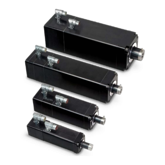
2.0 General Description Tolomatic IMA Actuators Figure 2.1: Tolomatic IMA Actuator The IMA is a compact, durable, high force rod-style actuator. The IMA integrates a servo motor into the mechanical design to minimize the overall envelope. The patented design allows for easy re-lubrication without disassembly for extremely long service life. -
Page 11: Cable Routing
2.3 Cable Routing It is recommended that the power and signal cables for Tolomatic IMA Actuators be routed as far apart as possible to minimize electrical noise in communication cables. Over time, liquid contaminants such as oil and cleaning solutions may accumulate on the cables and into the connectors if they are an exposed type. -
Page 12: Emc Wiring Guidelines
2.5 EMC Wiring Guidelines Shielding and grounding Tolomatic supplied cables have the proper shielding and are recommended for proper installation. If additional or alternate cables are require, braided shield cables are recommended. The standard cables provided by Tolomatic have an overall braided shield. To minimize EMI and ensure system reliability, all shield drain wires from all cables should be tied to a common earth ground. -
Page 13: 3: Ima Actuator Product Configuration
- DA2: Allen Bradley VP - DB1: Bosch Rexroth MSK - DL1: Lenze MCS - DS1: Siemens 1F For performance data and specifications please refer to the Tolomatic IMA Actuator brochure #2700-4000 3.2 Standard Configurations and options NOTE Please see Tolomatic IMA Actuator brochure #2700-4000 for complete information on ordering codes. - Page 14 Figure 3.1: Tolomatic IMA Actuator ordering codes and descriptions 2700-4001_22 IMA Manual Last Revision: 12/14/2021...
-
Page 15: Screw Selection
3.2.1 Screw Selection Tolomatic IMA Actuator: RN04, RN05, RN10: Roller nuts with 4mm, 5mm or 10 mm lead. BN05, BN10, BN20, BN25: Ball nuts with 5mm, 10mm, 20mm or 25mm lead Contact Tolomatic for application review and assistance in selecting a screw technology. -
Page 16: Rod End Options
Include: Longer stroke length other than standard; White Paint; Food Grade Grease; Hex Rod; Special Options 3.2.10 Feedback Device Contact Tolomatic for application review and assistance in selecting feedback device. The IMA is offered with the following feedback device technologies as standard: Incremental, Resolver, and SICK Hiperface, SICK Hiperface DSL, and Heidenhain EnDat 2.2 multi-turn absolute feedback devices. -
Page 17: Servo Drive
3.2.12 Servo Drive The Tolomatic IMA Actuators functions in the same way as a brushless servo motor. A servo drive is used to power and control the actuator. Please consult the servo drive manufacturer when sizing and selecting a servo drive for use with Tolomatic IMA Actuator. -
Page 18: 4: Ima Mechanical Installation
Peak current ii) Voltage iii) Peak RPM iv) Max current frequency Figure 4.1: Typical connections for a single-axis system with an Tolomatic IMA Actuator with optional brake to a RSW servo system drive 4.2 General Operation General Operation The IMA actuator functions by translating the rotary motion of the integral brushless servo motor into linear motion using a screw mechanism. -
Page 19: Cold Temperature Startup Procedure
Care should be taken to not exceed the physical travel limits of the Tolomatic IMA Actuator. Doing so will cause the actuator to reach mechanical end of stroke internally. Although protected by the end of stroke bumpers, repeatedly reaching internal end of stroke can physically damage the screw and the internal components of the actuator. -
Page 20: Alignment
For bench or fixture setup and testing of Tolomatic IMA Actuators, the actuator thrust rod must be anti-rotated by a fixture and the actuator securely retained to the bench or fixture. Never use a hand held wrench/device to provide the anti-rotate function while the motor is powered as contact with the internal end of stroke may send the wrench/device flying and may harm the operator or damage the actuator. - Page 21 Figure 4.3: Do not carry IMA by connectors or cables. The Tolomatic IMA Actuator weight range is approximately 3.0 to 42 kg (6.6 to 92.6 lb). Special care must be taken when lifting this device. Do not carry by the connectors or cables. The connectors are not rated to support the weight of the actuator.
-
Page 22: Mounting
Thrust Rod Attachment The design of the Tolomatic IMA Actuator allows the extending rod to rotate. This provides simple setup of the actuator by allowing the user to rotate the rod and thread it in and out of the actuator for mechanical attachment or system testing. -
Page 23: Field Installation Of Aro (Anti Rotation) Option
For applications in which the load is free to rotate, Tolomatic offers the anti-rotation systems shown below. The anti-rotate option (ARO) is not a guide or support mechanism. It is intended only as an anti-rotate device. - Page 24 Improper alignment of the anti-rotate shaft may result in binding and / or side loading which may reduce the life of the actuator. Take precautions to cause no damage to the actuator’s grease zerk throughout the following process. 1. Assemble Fastener [#3] into the Anti-Rotate Clamp [#2] finger-tight, then back off one (1) turn. 2.
-
Page 25: 5: Electrical Installation
"motor data files" that dictate how the feedback must be set up on the motor. Tolomatic can provide many of these "data files" or the proper parameters to enter. Entering motor parameter data to some drives may require assistance from the drive manufacturer. -
Page 26: Feedback Commutation
In any case where it is determined that the feedback has become misaligned, or an drive change is made requiring the feedback to be aligned differently, it is recommended that Tolomatic be contacted and arrangements made to have that procedure performed. - Page 27 Figure 5.6: Back EMF Voltage vs Electrical Angle From a manufacturing viewpoint the utilization of a fixed current vector provides the simplest means for aligning a feedback device. Some manufacturers however will reference a motor’s back emf when discussing commutation angles.
- Page 28 Figure 5.8: Hall Alignment Resolver Feedback The Tolomatic IMA Actuator family is also offered with resolver feedback. A resolver must be excited with a sinusoidal Input and outputs two signals, commonly referred to as cos and sin. These signal’s magnitude and the phase angle relative to the excitation voltage are used by the drive to determine the absolute position (single rotational) of the motor’s armature.
-
Page 29: Feedback Specifications
Figure 5.10: Motor rotational position at 90 Servomotor Information: For performance data and specifications please refer to the Tolomatic IMA Actuator brochure #2700-4000 5.5 Feedback Specifications ALL SIZES ALL SIZES DIGITAL Quantum ABSOLUTE Stegmann SKM36 ENCODER (Dx1A1x) Input Voltage 5 VDC (+/-5%) -
Page 30: Thermal Sensor Specifications
IMA22, IMA33, IMA44, IMA55 IMA22, IMA33, IMA44, IMA55 RESOLVER Dynapar BRC RESOLVER Dynapar BRX Input Voltage 7 Vrms (+/- 10%) Input Voltage 4 Vrms (+/- 5%) Excitation 10 kHz Excitation Frequency 5 kHz Frequency Max Input Current 40 mA Max Input Current 45 mA Transformation 0.5 (+/-10%) -
Page 31: Connector Pinouts
NOTE: The IMA is manufactured with your choice of several different connectors to be compliant with popular motor and drive manufacturers. Be sure to also reference all manufacturer material to insure proper connections. 5.7.1 Tolomatic Standard - DT1 5.7.1.1 Motor Power Connector - DT1xxx Manufacturer: Intercontec Intercontec Part No.: BEDC 106 MR14 00 1216 000... - Page 32 5.7.1.3 Digital Incremental Connector - DT1 D1x Manufacturer: Intercontec Intercontec Part No.: AEDC 113 MR83 00 1215 000 Name Name Temp - Temp + Hall U Hall U- Hall V Hall V- +5 Vdc Hall W Hall W- 5.7.1.4 Digital Incremental Cable Wiring (Flying Leads) for DT1 D1x IMA22, IMA33, IMA44 &...
- Page 33 Brake Information: 24 Vdc power is required to release the brake during operation. Ensure that pins 5 and 6 in the power connector are used for the brake. Thermal Device: Motor equipped with thermal switch at 100C. Tolomatic recommends the use of the thermal switch in order to protect the actuator in higher ambient temperatures.
- Page 34 Brake Information: 24 Vdc power is required to release the brake during operation. Ensure that pins 5 and 6 in the power connector are used for the brake. Thermal Device: Motor equipped with thermal switch at 100C. Tolomatic recommends the use of the thermal switch in order to protect the actuator in higher ambient temperatures.
- Page 35 Brake Information: 24 Vdc power is required to release the brake during operation. Ensure that pins 5 and 6 in the power connector are used for the brake. Thermal Device: Motor equipped with thermal switch at 100C. Tolomatic recommends the use of the thermal switch in order to protect the actuator in higher ambient temperatures.
-
Page 36: Allen Bradley Mp Motor Series - Da1
Brake Information: 24 Vdc power is required to release the brake during operation. Ensure that pins F and G in the power connector are used for the brake. Thermal Device: Motor equipped with thermal switch at 100C. Tolomatic recommends the use of the thermal switch in order to protect the actuator in higher ambient temperatures. -
Page 37: Allen Bradley Vp Motor Series - Da2
Brake Information: 24 Vdc power is required to release the brake during operation. Ensure that pins F and G in the power connector are used for the brake. Thermal Device: Motor equipped with Vishay temperature sensor. Tolomatic recommends the use of the thermal switch in order to protect the actuator in higher ambient temperatures. -
Page 38: Bosch Rexroth Msk Motor Series - Db1
Brake Information: 24 Vdc power is required to release the brake during operation. Ensure that pins 7 and 8 in the power connector are used for the brake. Thermal Device: Motor equipped with thermal switch at 100C. Tolomatic recommends the use of the thermal switch in order to protect the actuator in higher ambient temperatures. -
Page 39: Control Techniques Fm Motor Series - De1
Brake Information: 24 Vdc power is required to release the brake during operation. Ensure that pins 5 and 6 in the power connector are used for the brake. Thermal Device: Motor equipped with thermal switch at 100C. Tolomatic recommends the use of the thermal switch in order to protect the actuator in higher ambient temperatures. - Page 40 Brake Information: 24 Vdc power is required to release the brake during operation. Ensure that pins 5 and 6 in the power connector are used for the brake. Thermal Device: Motor equipped with thermal switch at 100C. Tolomatic recommends the use of the thermal switch in order to protect the actuator in higher ambient temperatures.
-
Page 41: Control Techniques Nt Motor Series - De2
Brake Information: 24 Vdc power is required to release the brake during operation. Ensure that pins B and C in the power connector are used for the brake. Thermal Device: Motor equipped with thermal switch at 100C. Tolomatic recommends the use of the thermal switch in order to protect the actuator in higher ambient temperatures. -
Page 42: Lenze Mcs Motor Series - Dl1
Brake Information: 24 Vdc power is required to release the brake during operation. Ensure that pins 1 and 2 in the power connector are used for the brake. Thermal Device: Motor equipped with thermal switch at 100C. Tolomatic recommends the use of the thermal switch in order to protect the actuator in higher ambient temperatures. - Page 43 5.7.7.3 Resolver Connector - DL1 D1x Manufacturer: Intercontec Intercontec Part No.: AEDC 052 MR83 00 1215 000 Name Exc Lo Cos Lo Keyed Center Sin Lo Temp + Temp - 5.7.7.4 Multi-turn Absolute Encoder Connector - DL1 A1x Manufacturer: Intercontec Intercontec Part No.: AEDC 052 MR83 00 1215 000 Name Name...
-
Page 44: Siemens 1F Motor Series - Ds1
5.7.8 Siemens 1F Motor Series - DS1 5.7.8.1 Motor Power Connector - DS1 xxx Manufacturer: Intercontec Intercontec Part No.: BEDC 106 MR14 00 1216 000 Name Phase R Phase S **Required GND** *Connect brake only when *BR + present *BR – Phase T 5.7.8.2 MultiTurn Absolute Encoder Connector - DS1 H1x Manufacturer: Intercontec... -
Page 45: 6: Ima Operation And Start Up Considerations
6.2 Brake In all vertical application an un-powered Tolomatic IMA Actuator will require a brake to maintain position. Tolomatic recommends that the nominal back drive force specification (listed on page 52) be used for reference only. Back drive force is subject to change throughout the life of the actuator, due to mechanical break in, ambient temperature, and duty cycle variation. - Page 46 Figure 6.2: Increased Engage / Disengage time, best protection 2700-4001_22 IMA Manual Last Revision: 12/14/2021...
-
Page 47: 7: Ima Repair And Maintenance
7.1 Lubrication NEW UNIT: All Tolomatic IMA Actuators have been lubricated at the factory and are ready for installation. If the actuator is placed in storage for more than 1 year after it is received, the actuator should be lubricated through the lubrication port on the thrust rod with Mobilith SHC220 #2744-1016 (QUANTITY: IMA33: 3.0 g;... - Page 48 Re-lubricate with Mobilith SHC220 #2744-1016 • (QUANTITY: IMA33: 3.0 g; IMA44: 5.0 g; IMA55: 7.0 g) into the grease zerk located on the rod end. IMA22 ball-screw does not require relubrication. • BALL SCREW LUBRICATION (Example Calculation) Cycle Details: Product: IMA33 BN : 1.66 in/sec : 400 lbf : 400 lbf...
- Page 49 Step 3: The Lubrication Interval (t ) for a given cycle is then calculated as: = 2019 (hours) x 0.87 = 1757 (hours) Tolomatic recommends validating the output force after 100 000 cycles and on an annual basis thereafter. 2700-4001_22 IMA Manual Last Revision: 12/14/2021...
-
Page 50: Procedure For Lubrication
Zerk on the rod end of the actuator: Re-apply power to the Tolomatic IMA Actuator Complete five full extend / full retract moves of the Tolomatic IMA Actuator at low speed / low force to properly distribute the grease Do not over-fill with grease Overfilling will cause a reduction in performance, excessive heat build up and potential premature failure. - Page 51 The rod bearing/wiper assembly can be removed, after grease zerk removal, by threading it out of the front plate using a spanner wrench. A new rod bearing/wiper assembly can then be reinstalled. To have this service performed for you, contact Tolomatic. IMA22, 33, 44 & 55 Manufactured after July 16, 2013 IMA22, 33, 44 and 55 have a replaceable wiper only.
-
Page 52: Storage Recommendations
• Store in clean and dry environment. • After six (6) months of storage it is recommended to cycle two complete strokes of the Tolomatic IMA Actuator to • redistribute the internal lubricants. It is also recommended to cycle the Tolomatic IMA Actuator two complete strokes before placing in service. -
Page 53: Appendix A: Specifications
Refer to the charts for the continuous and peak thrust and speed capabilities of the screw selections. NOTE: IMA integrated motor rod-style actuators are designed to move guided and supported loads and are not designed for applications that require significant side loading. Please contact Tolomatic at 1-800-328-2174 or 763- 478-8000 for details regarding side loading capabilities. -
Page 54: Critical Speed
& velocity must fall within the peak region of the actuator system. Higher peak thrusts are achievable by the actuator system, so please consult Tolomatic before exceeding catalog ratings. Use the following formulas when calculating the RMS thrust & velocity. When selecting a servo motor actuator system, it is recommended to add a margin of safety of 15% to the thrust and velocity required to move the load. -
Page 55: Appendix B: Troubleshooting Procedure
Actuator has crashed into hard stop Disconnect from load and manually move away from hard stop. If problem persists, contact Tolomatic for service. Actuator housing moves Loose mounting Check actuator mounting or vibrates when shaft is Drive is improperly tuned –... -
Page 56: Appendix C: Warranty
Limited Warranty Tolomatic warrants that at the time of delivery, Products shall be in good condition, free from defects in material and workmanship and that Products made to order shall conform to applicable drawings or specifications as referenced in the quotation or accepted purchase order (“Product Warranty”). The Product Warranty shall expire one year from date of shipment (the “Warranty Period”). - Page 57 Except insofar as specifications or drawings form part of a purchase order and the Product Warranty, to the full extent permitted by law, Tolomatic disclaims and Buyer waives all representations, warranties and covenants that may be implied from the provision by Tolomatic of technical advice or information about Product.
-
Page 58: Appendix D: Declaration Of Conformity
D: D PPENDIX ECLARATION OF ONFORMITY 2700-4001_22 IMA Manual Last Revision: 12/14/2021... - Page 59 © 2021 Tolomatic Tolomatic. All rights reserved. Tolomatic and Excellence In Motion are registered trademarks of Tolomatic Incorporated. All other products or brand names are trademarks of their respective holders. www.tolomatic.com 2700-4001_22 IMA Manual Last Revision: 12/14/2021...
Need help?
Do you have a question about the IMA Series and is the answer not in the manual?
Questions and answers