Table of Contents
Advertisement
Quick Links
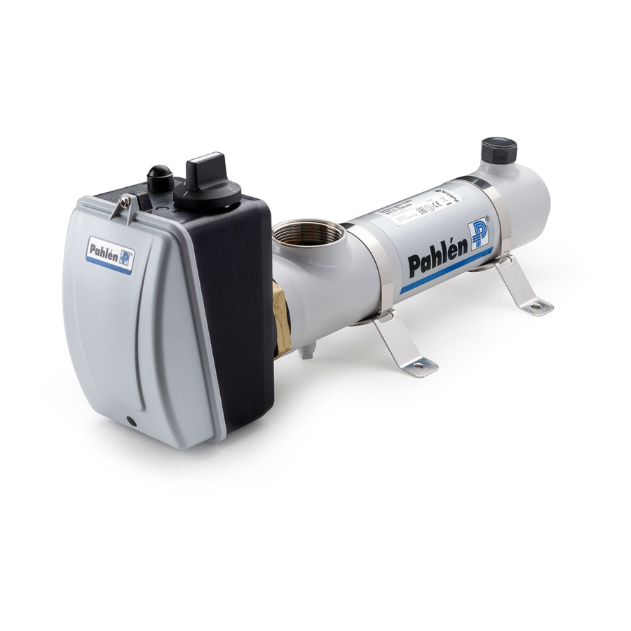
Compact electric heater
The Compact electric heater is available with outputs from 3kW to 18kW, see identity plate placed on the body. It shall by safety reasons
be equipped with a flow switch or a pressure switch. In the connection box a thermostat and/or an overheating limit control can be
mounted. The standard heater must not be used in aggressive water, salt water or in pools where a salt/chlorinator is used. In such
circumstances a Compact electric heater Titanium/Nic-tech is required.
Follow these instructions:
Safety
If the heater is mounted against inflammable material the installer must place a gypsam wallboard between the heater and the inflam-
mable wall. The board must protrude a minimum of 10 cm outside the body of the heater. The heater must not be covered, enclosed
in or placed near inflammable material.
Assembly the heater
The connection box shall be mounted on the body/heating element as shown in picture 2. Accessories like overheating limit control
and/or thermostat shall be mounted in the box according to the separate instruction included in the kits.
The flow switch shall be mounted so the direction of the arrow on the flow switch housing comply with the direction of the water flow.
The pressure switch shall be connected to terminal block 1 and 3.
Pipe installation
The pipe installation must be done before the electric installation. The electric heater must be installed in a horizontal position on the
return pipe to the pool, after the filter, so that it is flooded at all times, see installation illustration. The heater may be installed in a vertical
position only if there is a positive pressure of water in the tubes of at least 50 cm.
Do not install a gate valve between heater and pool. If a valve is required, install a check valve.
Dosage of chlorine, acid or similar, must be done after the heater in the flow direction to avoid corrosion.
In case of climates with sub-zero temperatures the heater must be installed so that it can be emptied.
Electric installation
The electric installation must be done by a licenced electrician.
The heater shall be connected over one or two contactors, depending on type of heater, see wiring diagram.
Connect earth to heating element according to picture 2.
The heater shall be installed in such way that it cannot be activated if the circulation pump is not working (sufficient flow), i.e. the power
supply to the contactor must be guided over the motor protection of the pump.
Start
1. Start the pump of the pool water circulation.
2. Check that the water circulation is normal before the heater is turned on.
3. Test the heater by turning the thermostat knob back and forth and check that the contactor of the thermostat turns on and off.
Check any flow switch or pressure switch by turning off the flow through the heater with a gate valve and control that the
contactor is beeing deenergized.
4. Set desired pool water temperature by turning the thermostat knob.
5. The heater will now heat the pool water to desired temperature.
Management
When back-washing and cleaning the filter, the power to the heater must be turned off.
The heater must be drained before it is exposed to sub-zero temperatures or if the pool system is closed for a longer time.
If the heater does not start
a) Check the fuses.
b) The overheating limit control is released:
-Losen the protective cap, see fig beside.
-Press the reset button on the connection box.
-Put the cap back.
c) Any pressure switch is not closed: The pressure switch is pre-installed on 0,2 bar. If a correct pressure is not attainable, the return
pipe to the pool shall be somewhat cut down in order to increase the back pressure in the return pipe.
d) Check that the direction of the arrow on the flow switch housing agree to the direction of the water flow.
e) Reset the thermostat to a higher temperature.
Pahlén AB, Box 728, SE-194 27 Upplands Väsby, Sweden
Tel. +46 8 594 110 50, Fax +46 8 590 868 80, e-mail: info@pahlen.se, www.pahlen.com
1½"
1/8" -
Chlorine content:
Chloride (salt) content:
pH-value:
Alkalinity:
Calcium hardness:
Max temperature:
Max pressure without pressure switch:
Max pressure with pressure switch:
Minimum flow without flow switch:
Minimum flow with flow switch:
Pressure switch here
Stainless steel/Incoloy
max 3 mg/l (ppm)
max 250 mg /l
7,2 - 7,8
60-120 mg/l (ppm)
200-1000 mg/l (ppm)
110°C
10 bar
2,5 bar
20 l/min
85 l/min
A ( 1 : 1 )
Protective cap
Cap
A
Surface treatment
E
The tolerance class in accordance with this
part of ISO 2768-1
½" -
Flow switch here
Picture 1
1½"
Titanium/Nic-Tech
max 3 mg/l (ppm)
-
7,2 - 7,8
60-120 mg(l (ppm)
200-1000 mg/l (ppm)
110°C
10 bar
2,5 bar
20 l/min
85 l/min
A ( 1 : 1 )
Protective cap
Reset button
Reset button
A
Monteringsanvisning
MA45-19E
Designed by:
Drawn by: Date
Approved by:
TS
2012-06-21
Surface treatment
E
Assembly drawing no.
Art.no.
The tolerance class in accordance with this
Assembly drawing no.
Demontering lock
Scale
Revised by: Date
part of ISO 2768-1
Cap
2013
Designed by:
Drawn by: Date
Approved by:
TS
2012-06-21
Art.no.
Scale
Revised by: Date
Advertisement
Table of Contents

Related Manuals for Pahlen Compact


Summary of Contents for Pahlen Compact
- Page 1 Pressure switch here The Compact electric heater is available with outputs from 3kW to 18kW, see identity plate placed on the body. It shall by safety reasons be equipped with a flow switch or a pressure switch. In the connection box a thermostat and/or an overheating limit control can be mounted.
- Page 2 Pressure 3-pole switch or Blue flow switch Overheating limit control Thermostat Thermostat Monteringsanvisning Pahlén AB, Box 728, SE-194 27 Upplands Väsby, Sweden MA45-19E Tel. +46 8 594 110 50, Fax +46 8 590 868 80, e-mail: info@pahlen.se, www.pahlen.com 2013...
Need help?
Do you have a question about the Compact and is the answer not in the manual?
Questions and answers