Table of Contents
Advertisement
Quick Links
R e a d a l l o p e r a t i n g i n s t r u c t i o n s b e f o r e i n s t a l l i n g ,
c o n n e c t i n g ( w i r i n g ) , o p e r a t i n g , s e r v i c i n g , o r i n s p e c t i n g
t h e i n v e r t e r .
E n s u r e t h a t t h i s ma n u a l i s ma d e a v a i l a b l e t o t h e e n d u s e r o f
t h e i n v e r t e r .
S t o r e t h i s ma n u a l i n a s a f e , c o n v e n i e n t l o c a t i o n .
T T h e ma n u a l i s s u b j e c t t o c h a n g e w i t h o u t p r i o r n o t i c e .
Downloaded from Dealers Industrial Equipment -- Visit
E 5 1 0
https://DealersElectric.com
I N V E R T E R
I N S T R U C T I O N MA N U A L
2 3 0 V C l a s s 1 ~
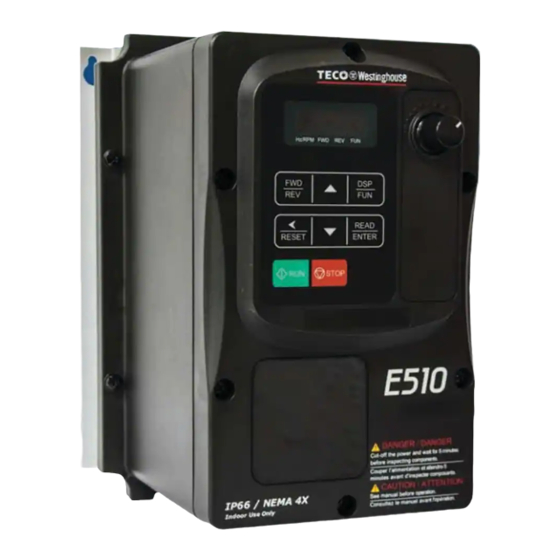
I P 6 6 / N E M A 4 X
0 . 4 - 2 . 2 k W / 0 . 5 - 3 H P
2 3 0 V C l a s s 3 ~
I P 6 6 / N E M A 4 X
0 . 4 - 1 5 k W / 0 . 7 5 - 2 0 H P
4 6 0 V C l a s s 3 ~
4 6 0 V
I P 6 6 / N E M A 4 X
0 . 4 5 - 1 8 . 5 k W / 1 - 2 5 H P
or call (908) 688-1966 for all of your Teco needs!
D O C U ME N T - T E C O - E 5 1 0 I M
V e r 0 1 : 2 0 1 5 . 0 8
Advertisement
Table of Contents
Troubleshooting

Related Manuals for Westinghouse Teco E510


Summary of Contents for Westinghouse Teco E510
- Page 1 I N V E R T E R E 5 1 0 I N S T R U C T I O N MA N U A L 2 3 0 V C l a s s 1 ~ I P 6 6 / N E M A 4 X 0 .
-
Page 2: Table Of Contents
**** STATEMENT **** Si Desea descargar el manual en español diríjase a este Link: www.tecowestinghouse.com Table of Contents Preface (English) ............................0-1 Preface (Français) ............................0-2 1 Safety Precautions (English) ........................1-1 1.1 Before Supplying Power to the Inverter ....................1-1 1.2 Wiring ................................ - Page 3 3.3 Removing the Front Cover and Keypad....................3-3 3.4 Inverter Exterior ............................3-5 3.5 Wire Gauges, Tightening Torque and Short Circuit Rating ..............3-8 3.6 Wiring Peripheral Power Devices ......................3-9 3.7 General Wiring Diagram .......................... 3-11 3.8 User Terminals ............................3-12 3.9 Power Terminals .............................
- Page 4 7. Operation Method Configuration (Run / Stop) ..................7-1 7.1 Run / Stop from the Keypad ........................7-1 7.2 Run / Stop from External Switch / Contact or Pushbutton ................ 7-2 7.3 Run / Stop from Serial Communication RS485 ..................7-4 8.
-
Page 5: Preface (English)
Preface (English) The E510 product is an inverter designed to control a three-phase induction motor. Please read this manual carefully to ensure correct operation, safety and to become familiar with the inverter functions. The E510 inverter is an electrical / electronic product and must be installed and handled by qualified service personnel. -
Page 6: Preface (Français)
Préface (Français) Le produit est un lecteur conçu pour commander un moteur à induction triphasé. lire attentivement ce manuel pour garantir le bon fonctionnement, la sécurité et pour se familiariser avec les fonctions d'entraînement. Le lecteur est un appareil électrique / électronique et doit être installé et géré par un personnel qualifié ... -
Page 7: Safety Precautions (English)
1. Safety Precautions (English) 1.1 Before supplying Power to the Inverter Warning The main circuit must be correctly wired. For single phase supply use input terminals (R/L1, T/L3) and for three phase supply use input terminals (L1(L), L2, L3(N)). Terminals T1, T2, T3 must only be used to connect the motor. -
Page 8: Wiring
1.2 Wiring Warning Always turn OFF the power supply before attempting inverter installation and wiring of the user terminals. Wiring must be performed by a qualified personnel / certified electrician. Make sure the inverter is properly grounded. (230V Class: Grounding impedance shall be less than 100Ω. -
Page 9: Before Operation
1.3 Before Operation Warning Make sure the inverter capacity matches the parameters 13-00. Reduce the carrier frequency (parameter 11-01) If the cable from the inverter to the motor is greater than 80 ft (25m). A high-frequency current can be generated by stray capacitance between the cables and result in an overcurrent trip of the inverter, an increase in leakage current, or an inaccurate current readout. -
Page 10: Operation
1.5 Operation Warning Be sure to install all covers before turning on power. Do not remove any of the covers while power to the inverter is on, otherwise electric shock may occur. Do not connect or disconnect the motor during operation. This will cause the inverter to trip and may cause damage to the inverter. -
Page 11: Maintenance, Inspection And Replacement
1.6 Maintenance, Inspection and Replacement Warning Wait a minimum of five minutes after power has been turned OFF before starting an inspection. Also confirm that the charge light is OFF and that the DC bus voltage has dropped below 25Vdc. ... -
Page 12: Consignes De Sécurité (Français)
1. Consignes de sécurité (Français) 1.1 Avant d'alimenter le disque dur Avertissement Le circuit principal doit être correctement câblée. Pour les terminaux monophasés d'approvisionnement de l'utilisation des intrants (R/L1, T/L3) et de trois bornes d'entrée de l'utilisation de l'offre de phase (R/L1, S/L2, T/L3). -
Page 13: Avant L'opération
Attention La tension d'alimentation appliquée doit se conformer à la tension d'entrée spécifiée par le lecteur. (Voir la section signalétique du produit) Raccorder la résistance de freinage et de l'unité de freinage sur les bornes assignées. Ne pas brancher une résistance de freinage directement sur les bornes CC P (+) et N (-), sinon risque d'incendie. -
Page 14: Opération
1.5 Opération Avertissement Veillez à installer tous les couvercles avant de l'allumer. Ne retirez pas les capots pendant que l'alimentation du lecteur est allumé, un choc électrique peut se produire autrement. Ne pas brancher ou débrancher le moteur pendant le fonctionnement. Le variateur pourrai se déclencher et ainsi endommager le lecteur. -
Page 15: Mise Au Rebut Du Variateur
Attention Le variateur peut être utilisé dans un environnement avec une gamme de température allant de 14 ° -104 ° F (10-40 ° C) et l'humidité relative de 95% sans condensation. Le variateur doit être utilisé dans un environnement sans poussière, gaz, vapeur et humidité. 1.7 Mise au rebut du variateur Attention ... -
Page 16: Model Description
2. Model Description 2.1 Nameplate Data It is essential to verify the E510 inverter nameplate and make sure that the E510 inverter has the correct rating so it can be used in your application with the proper sized AC motor. Unpack the E510 inverter and check the following: (1) The E510 inverter and start-up and installation manual (this document) are contained in the package. -
Page 17: Inverter Models - Motor Power Rating
2.2 Inverter Models – Motor Power IP66 / NEMA 4X Type Supply Filter Switch Frame Model voltage (kW) Size (Vac) ◎ ◎ ◎ E510-2P5-H1FN4S 1 Phase ◎ ◎ ◎ E510-201-H1FN4S 0.75 200~240V +10%-15% ◎ ◎ ◎ E510-202-H1FN4S 50/60Hz ◎ ◎ ◎... -
Page 18: Environment And Installation
3. Environment and Installation 3.1 Environment The environment will directly affect the proper operation and the life span of the inverter. To ensure that the inverter will give maximum service life, please comply with the following environmental conditions: Protection Protection Class IP66 / NEMA 4X (Depending on models) Operating IP66 / NEMA 4X type: -10°C - +50°C (14-122 °F) -
Page 19: Warning Labels
3.2 Warning Labels Important: Warning information located on the front cover must be read upon installation of the inverter. Downloaded from Dealers Industrial Equipment -- Visit https://DealersElectric.com or call (908) 688-1966 for all of your Teco needs! -
Page 20: Removing The Front Cover And Keypad
3.3 Removing the Front Cover and Keypad Caution Before making any wiring connections to the inverter the front cover needs to be removed. IP66 / NEMA 4X Step 1: Unscrew cover and place cover next to the inverter Downloaded from Dealers Industrial Equipment -- Visit https://DealersElectric.com or call (908) 688-1966 for all of your Teco needs! - Page 21 Step 2: Remove the rubber plugs and use the waterproof cable glands provided to connect cables. Step 3: Connect power & motor cables through the cable glands to the correct terminals Step 4: Connect power & motor cables through the cable glands to the correct terminals Downloaded from Dealers Industrial Equipment -- Visit https://DealersElectric.com or call (908) 688-1966 for all of your Teco needs!
-
Page 22: Inverter Exterior
3.4 Inverter Exterior IP66/NEMA4X Single/Three phase: 230V 0.5~1HP Single phase: 230V 0.5~1HP Three phase: 230V 2HP; 460V 1~2HP E510-Frame 1 (IP66/NEMA 4X With/Without VR and disconnect switches depending on the model) Downloaded from Dealers Industrial Equipment -- Visit https://DealersElectric.com or call (908) 688-1966 for all of your Teco needs! - Page 23 Single/Three phase: 230V 2~3HP Single phase: 230V 2~3HP Three phase: 230V 5HP; 460V 3~5HP E510-Frame 2 (IP66/NEMA 4X With/Without VR and disconnect switches depending on the model) Downloaded from Dealers Industrial Equipment -- Visit https://DealersElectric.com or call (908) 688-1966 for all of your Teco needs!
- Page 24 Three phase: 230V 7.5~20HP; 460V 7.5~25HP E510-Frame 3 (IP66/NEMA 4X With/Without VR and disconnect switches depending on the model) Downloaded from Dealers Industrial Equipment -- Visit https://DealersElectric.com or call (908) 688-1966 for all of your Teco needs!
- Page 25 3.5 Wire Gauges, Tightening Torque, Terminal and Short Circuit Ratings. To comply with UL standards, use UL approved copper wires (rated 75° C) and round crimp terminals (UL Listed products) as shown in table below when connecting to the main circuit terminals. Model Cable Size Tightening torque...
-
Page 26: Wiring Peripheral Power Devices
3.6 Wiring Peripheral Power Devices Caution After power is shut off to the inverter the capacitors will slowly discharge. Do NOT touch and of the inverter circuitry or replace any components until the “CHARGE” indicator is off. Do NOT wire or connect/disconnect internal connectors of the inverter when the inverter is powered up or when powered off and the “CHARGE””... - Page 27 Power supply: ~ ~ ~ Power Supply Make sure the correct voltage is applied to avoid damaging the inverter. Molded Molded-case circuit breaker (MCCB) or fused disconnect: Circuit A molded-case circuit breaker or fused disconnect must be installed Breaker between the AC source and the inverter that conforms to the rated voltage and current of the inverter to control the power and protect the...
-
Page 28: General Wiring Diagram
3.7 General Wiring Diagram AC Input Voltage Braking Resistor L1(R) L2(S) L3(T) 3Ø Induction motor L1(L) L3(N) Ground < 100Ω RS485 FWD / STOP CON 2 1:Data+ REV / STOP 2:Data- 3:Data+ Preset Speed 1 4:RXD0 5:TXD0 Multi- Preset Speed 2 6:Data- Functional Digital Input... -
Page 29: User Terminals
3.8 User Terminals (Control Circuit Terminals) R2A R2B 24V AI1 R1A R1B R1C AGND Jumper function descriptions Jumper Symbol Funct ion Si gn al R ef er en c e Note NPN Input J P 1 NPN/PNP selectable Factory default setting PNP Input 0~20mA / 4~20mA Set parameters... - Page 30 Description of User Terminals Type Terminal Terminal function Signal level Forward- Stop (Preset), Multi-function input terminal Reverse - Stop (Preset), Multi-function input terminal 24 VDC, 8 mA, Optical Digital Preset Speed0(5-02),Multi-function input terminal coupling isolation (Max, input voltage 30 VDC, Preset Speed1(5-03), Multi-function input terminal signal Input impedance 3.3kΩ)
- Page 31 Notes: *1:Multi-function digital input can be referred to in this manual. - Group 03: External Terminals Digital Input / Output Function Group. *2:Multi-function analog input can be referred to in this manual.. - Group 04 - External Terminal Analog Signal Input (Output) Function Group. *3:Multi-function analog output can be referred to in this manual.
-
Page 32: Power Terminals
3.9 Power Terminals 230V: 0.5 ~ 20HP Terminal 460V: 1 ~ 25HP L1(L) Input Power Supply (For single phase use terminals L1(L) and L3(N) L3(N) Braking resistor connection terminal: For use in applications requiring a high inertia load to stop rapidly. (Refer to specifications of the braking resistor). - Page 33 Frame 2 230V: 2 ~ 3HP (Single Phase) 230V: 2 ~ 3HP (Single / Three Phase) 230V: 5HP (Three Phase) 460V: 3 ~ 5HP (Three Phase) Frame 3 & 4 230V: 7.5 ~ 20HP (Three Phase) 460V: 7.5 ~ 25HP (Three Phase) Notes: For wire gauges and screw torques, please refer to the table in section 3.6.
-
Page 34: Inverter Wiring
3.10 Inverter Wiring Wiring Precautions Do NOT remove any protective covers or attempt any wiring while input power is applied. Connect all wiring before applying input power. When making wiring changes after power up, remove input power and wait a minimum of five minutes after power has been turned off before starting. - Page 35 (B) Grounding Connect the ground terminal (E) to ground having a resistance of less than 100Ω. Do not share the ground wire with other devices, such as welding machines or power tools. Always use a ground wire that complies with the local codes and standards for electrical equipment and minimize the length of ground wire.
-
Page 36: Input Power And Motor Cable Length
3.11 Input Power and Motor Cable Length The length of the cables between the input power source and /or the motor and inverter can cause a significant phase to phase voltage reduction due to the voltage drop across the cables. The wire size shown in Tables 3.16.1 is based on a maximum voltage drop of 2%. -
Page 37: Power Input Wire Size And Nfb
3.14 Power Input Wire Size, and NFB The following table shows the recommended wire size for each frame of the E510. It depends on the application whether or not to install a circuit breaker. The NFB must be installed between the input power supply and the inverter input (L1 (L), L2, L3 (N)). -
Page 38: Inverter Specifications
3.16 Inverter Specification Product Specifications 230V class – Single Phase Model:E510-□□□- H1F(N4)(S) Horse power (HP) Suitable motor capacity (kW) 0.75 Rated output current (A) 10.5 Rated capacity (KVA) 2.90 4.00 Input voltage range(V) Single Phase:200~240V,50/60Hz Allowable voltage fluctuation +10%-15% Output voltage range(V) Three phase: 0~240V Input current (A)* 23.9... - Page 39 Product Specifications 230V class –Three Phase Model: E510-□□□- H3(N4) Horse power (HP) Suitable motor capacity (kW) Rated output current (A) 17.5 Rated capacity (KVA) 13.3 20.6 27.4 Input voltage range(V) Three phase :200~240V,50/60HZ Allowable voltage fluctuation +10%-15% Output voltage range(V) Three phase: 0~240V Input current (A)* 20.5...
- Page 40 Product Specifications 460V class –Three Phase Model: E510-□□□- H3(F)(PT) Horse power (HP) Suitable motor capacity ( kW ) 18.5 Rated output current (A) Rated capacity (KVA) 27.4 Three phase: 380~480V (+10%-15%),50/60Hz Input voltage range(V) Three phase: 0~480V Output voltage range(V) Input current (A)* Allowable momentary power loss time (S) Enclosure...
-
Page 41: General Specifications
General Specifications Item E510 Control Mode V/F Control, Vector Control Output Frequency 0.01~650.00Hz Starting Torque 150%/1Hz(Vector) Speed Control Range 1:50 Digital input: 0.01Hz Setting resolution Analog input:0.06Hz/60Hz Keypad: Set directly with▲▼ keys or the VR on the Frequency keypad External Input Terminals: Setting AI1(0/2~10V), AI2(0/4~20mA)input Multifunction input up/down function(Group3) - Page 42 Short-circuit output Electronic Circuit Protection terminal Grounding Fault Electronic Circuit Protection Protection for overheating of heat sink, The carrier Other protection frequency decreases based on the temperature, Fault features output, Reverse prohibit, Prohibit for direct start after power up and error recovery ,parameter lock up All frames include brake transistor Standard built-in RS485 communication (Modbus), One Communication control...
-
Page 43: Inverter Derating Based On Carrier Frequency
3.17 Inverter derating based on Carrier Frequency Frame 1 / 2 / 3 / 4 Single phase: 230V: 0.5~3HP; Single /Three phase: 230V: 0.5~3HP; Three phase: 230V: 2~20HP, 460V: 1~25HP) Current Rating 100% Carrier Frequency(kHz) Note: De-rate curve for ambient temperature of 104°F (40°C). De-rate curve for ambient temperature of 122°F (50°C). -
Page 44: Inverter Dimensions
3.18 Inverter Dimensions IP66 / NEMA 4X Dimensions Frame 1 (IP66 / NEMA 4X) Single phase: 230V 0.5~1HP Single / Three phase: 230V 0.5~1HP Three Phase: 230V 2HP; 460V 1~2HP 3-27 Downloaded from Dealers Industrial Equipment -- Visit https://DealersElectric.com or call (908) 688-1966 for all of your Teco needs! - Page 45 Unit: mm(inch) Model Dimensions (kg) E510-2P5-HN4R (7.87) E510-2P5-H1FN4S (7.87) (7.87) E510-201-HN4R (7.87) 150.8 133.3 248.7 230.2 214.2 49.5 10.6 E510-201-H1FN4S (5.94) (5.25) (9.79) (9.06) (8.43) (7.20) (1.95) (0.21) (0.21) (0.42) (7.87) (7.87) E510-401-H3N4 E510-401-H3FN4S (7.87) (7.87) E510-402-H3N4 E510-402-H3FN4S 3-28 Downloaded from Dealers Industrial Equipment -- Visit https://DealersElectric.com or call (908) 688-1966 for all of your Teco needs!
- Page 46 Frame 2 (IP66 / NEMA 4X) Single phase: 230V 2~3HP Single / Three phase: 230V 2~3HP Three Phase: 230V 5HP; 460V 3~5HP 3-29 Downloaded from Dealers Industrial Equipment -- Visit https://DealersElectric.com or call (908) 688-1966 for all of your Teco needs!
- Page 47 Unit: mm(inch) Model Dimensions (kg) 235.2 E510-202-HN4R (9.26) 235.2 235.2 E510-202-H1FN4S (9.26) (9.26) 235.2 E510-203-HN4R (9.26) 235.2 235.2 E510-203-H1FN4S 337.9 218.4 79.8 (9.26) (9.26) 5.98 (7.80) (4.53) (13.19) (12.40) (13.30) (8.60) (3.14) (0.28) (0.28) E510-205-H3N4 E510-403-H3N4 235.2 235.2 E510-403-H3FN4S (9.26) (9.26) E510-405-H3N4 235.2...
- Page 48 Frame 3 (IP66 / NEMA 4X) Three Phase: 230V 7.5~20HP; 460V 7.5~25HP 3-31 Downloaded from Dealers Industrial Equipment -- Visit https://DealersElectric.com or call (908) 688-1966 for all of your Teco needs!
- Page 49 Unit: mm(inch) Model Dimensions (kg) E510-208-H3N4 E510-210-H3N4 E510-215-H3N4 E510-220-H3N4 E510-408-H3N4 266.5 263.5 E510-408-H3FN4S (10.49) (10.37) 222.8 466.3 246.6 12.68 E510-410-H3N4 (8.77) (5.51) (18.11) (17.32) (18.36) (9.71) (3.78) (0.28) (0.28) 266.5 263.5 E510-410-H3FN4S (10.49) (10.37) E510-415-H3N4 266.5 263.5 E510-415-H3FN4S (10.49) (10.37) E510-420-H3N4 E510-425-H3N4 3-32...
-
Page 50: Keypad And Programming Functions
4. Keypad and Programming Functions 4.1 LED Keypad 4.1.1 Keypad Display and Keys LED Display Reverse Direction Forward Direction Status Indicator Status Indicator 8 button Membrane Keypad Frequency Potentiometer Run Key Stop Key DISPLAY Description 5 Digit LED Display Monitor inverter signals, view / edit parameters, fault / alarm display. LED INDICATORS Hz/RPM LED ON when frequency or line speed is displayed. - Page 51 4.1.2 Display Description Actual LED Display Actual LED Display Actual LED Display Actual LED Display ° Display output frequency Frequency Reference Set Frequency Reference LED lights on LED flashes Flashing digit At power-up the display will show the frequency reference setting, all LEDs are flashing. Press the ▲UP or ▼DOWN key to enter the frequency reference edit mode, use the ◄/ENT key to select which digit to edit (flashing).
- Page 52 LED display examples Seven Segment display Description 1. Displays the frequency reference at power-up 2. Display the actual output frequency in operation status. Display parameter code Display the setting value of parameter Display input voltage Display inverter current. Display DC Bus Voltage Display temperature Display PID feedback value.
- Page 53 4.1.3 LED Status description Hz/ RPM LED State Description Hz/RPM LED Display doesn’t show frequency or line speed Illuminated Display shows frequency or line speed Forward LED State Description FWD LED Inverter in reverse direction Illuminated Inverter is running in forward direction Flashing Forward direction active, no run command Reverse LED...
- Page 54 4.1.4 Power-Up Monitor Power Up: DSP/ DSP/ After 2 sec. Display at Power-up Frequency Reference Parameter Selection Change Monitor at Power-Up 12-00 Display selection Highest bit -> 0 0 0 0 0 <- Lowest bit The setting range for each bit is 0 ~ 8 from the highest bit to the lowest bit. Range 0: No display 4: Temperature...
- Page 55 Example: 12-00 = 12345 DSP/ Heatsink Temperature <4> DSP/ DSP/ DC Voltage <3> Output Voltage <2> DSP/ DSP/ PID Feedback <5> After 2 sec. Display Voltage Class Output Current <1> Parameter Selection at Power-up DSP/ DSP/ Frequency Reference 4.1.5 Modifying Parameters / Set Frequency Reference Frequency Short Press: DSP/FUN...
- Page 56 4.1.6 Operation Control Stopped Running Stopping Stopped Output Frequency Indicator Indicator Downloaded from Dealers Industrial Equipment -- Visit https://DealersElectric.com or call (908) 688-1966 for all of your Teco needs!
-
Page 57: Parameters
4.2 Parameters Parameter group Name Group 00 Basic Parameters Group 01 V/F Control Parameters Group 02 Motor Parameters Group 03 External Digital Input and Output Parameters Group 04 External Analog Input and Output Parameters Group 05 Preset-Speed Parameters Group 06 Automatic Program Operation Parameters Group 07 Start /Stop Parameters... - Page 58 G r o u p 00: Basic parameters Factory Description Range Unit Note Setting 0:V/F Mode 00-00 Control Mode Selection 1:Vector Mode 00-01 Reserved 0:Keypad 1:External Run/Stop Control Main Run Command 00-02 2:Communication Source Selection 3:PLC 0:Keypad Alternative Run Command 00-03 1:External Run/Stop Control Source Selection...
- Page 59 G r o u p 01: V/F Control Parameters Factory Description Range Unit Note Setting 01-00 Volts/Hz Patterns 0~18 200V:170.0~264.0 01-01 V/F Max voltage 220.0/440.0 400V:323.0~528.0 01-02 Max Frequency 0.20 ~ 650.00 50.00/60.00 01-03 Max Frequency Voltage Ratio 0.0 ~ 100.0 100.0 01-04 Mid Frequency 2...
- Page 60 Group 03: External Digital Inputs and Relay Output Functions Factory Description Range Unit Note Setting 03-00 Multifunction Input Term. S1 0:Forward/Stop Command 03-01 1:Reverse/Stop Command Multifunction Input Term. S2 03-02 2:Speed Selection 1 Multifunction Input Term. S3 03-03 3:Speed Selection 2 Multifunction Input Term.
- Page 61 Group 03: External Digital Inputs and Relay Output Functions Factory Description Range Unit Note Setting ( Terminals R1A,R1B, R1C ) 1:Fault 2:Setting Frequency Reached 3:Frequency Reached. Set by (3-13±3-14) 4:Output Frequency Detection1(> 3-13) 5:Output Frequency Detection2(< 3-13) 6:Auto Restart 7:Momentary AC Power Loss 8:Rapid Stop 9:Base Block 10:Motor Overload Protection(OL1)
- Page 62 Group 04: External Analog Input and Output Parameters Factory Description Range Unit Note Setting (0): 0~10V (0~20mA) 0~10V (0~20mA) Analog Input Signal Type 04-00 (1): 0~10V (0~20mA) 2~10V (4~20mA) Select (AI1/AI2) (2): 2~10V (4~20mA) 0~10V (0~20mA) (3): 2~10V (4~20mA) 2~10V (4~20mA) 04-01 AI1 Signal Verification Scan Rate 1~200...
- Page 63 Group 05: Preset Speed Parameters Factory Description Range Unit Note Setting 0: Common Accel/Decel Accel/Decel 1 or 2 apply to all speeds Preset Speed Control 05-00 1: Individual Accel/Decel for each preset speed Mode Selection 0-15 apply to the selected preset speeds (Acc0/Dec0~Acc15/Dec15) Preset Speed 0 05-01...
- Page 64 Group 05: Preset Speed Parameters Factory Description Range Unit Note Setting 05-40 10.0 Preset Speed11-Dectime 05-41 10.0 Preset Speed12-Acctime 05-42 10.0 Preset Speed12-Dectime 05-43 10.0 Preset Speed13-Acctime 05-44 10.0 Preset Speed13-Dectime 05-45 10.0 Preset Speed14-Acctime 05-46 10.0 Preset Speed14-Dectime 05-47 10.0 Preset Speed15-Acctime 05-48...
- Page 65 Auto _ Run Mode 06-09 0.00 Frequency Command 9 Auto _ Run Mode 06-10 0.00 Frequency Command10 Auto _ Run Mode 06-11 0.00 Frequency Command 11 Auto _ Run Mode 06-12 0.00 Frequency Command 12 Auto _ Run Mode 06-13 0.00 Frequency Command 13 Auto _ Run Mode...
- Page 66 Auto_ Run Mode Running 06-32 Direction 0 Auto_ Run Mode Running 06-33 Direction 1 Auto_ Run Mode Running 06-34 Direction 2 Auto_ Run Mode Running 06-35 Direction 3 Auto_ Run Mode Running 06-36 Direction 4 Auto_ Run Mode Running 06-37 Direction 5 Auto_ Run Mode Running 06-38...
- Page 67 Group 07: Start/Stop Parameters Factory Description Range Unit Note Setting 0: Momentary Power Loss and Restart Disable Momentary Power Loss and 07-00 Restart 1: Momentary Power Loss and Restart Enable 07-01 Auto Restart Delay Time 0.0~800.0 Number of Auto Restart 07-02 0~10 Attempts...
- Page 68 Group 08: Protection Parameters Factory Description Range Unit Note Setting xxxx0: Enable Trip Prevention During Acceleration xxxx1: Disable Trip Prevention During Acceleration xxx0x: Enable Trip Prevention During Deceleration xxx1x: Disable Trip Prevention During Deceleration 08-00 Trip Prevention Selection 01000 xx0xx: Enable Trip Prevention in Run Mode xx1xx: Disable Trip Prevention in Run Mode...
- Page 69 Group 08: Protection Parameters Factory Description Range Unit Note Setting 0: Stop Output After Over Torque Detection (Free Run to Over torque protection Stop) 08-14 action 1: Continue Running After Over Torque Detection (Display only OL3) Over Torque Detection 08-15 30~300 Level Over Torque Detection...
- Page 70 Group 10: PID Parameters Factory Description Range Unit Note Setting 0: Potentiometer on Keypad 1: Analog Signal Input. (AI1) PID Target Value Selection 2: Analog Signal Input. (AI2) 10-00 (When 00-05\00-06=6 This Function is 3: Frequency Set by Communication Enabled) 4: Keypad Frequency Parameter 10-02 0: Potentiometer on Keypad...
- Page 71 Group 10: PID Parameters Factory Description Range Unit Note Setting 10-22 Min PID Feedback Setting Level 0 ~999 Group 11: Auxilary Parameters Factory Description Range unit Note Setting 0: Reverse Command is Enabled 11-00 Reverse Operation Control 1: Reverse Command is Disabled 11-01 Carrier Frequency (kHz) 1~16...
- Page 72 Group 12: Monitoring Parameters Factory Description Range Unit Note Setting 00000~88888 Each digit can be set from 0 to 8 as listed below. 0: Default Display (Frequency and Parameters) 1:Output Current 2:Output Voltage 12-00 3:DC Voltage Extended Display Mode 00000 4:Temperature 5:PID Feedback 6:Analog Signal Input.
- Page 73 Group 12: Monitoring Parameters Factory Description Range Unit Note Setting Display of Inrush Current 12-08 0~100 Suppression Circuit Display of Control Circuit 12-09 0~100 Capacitors 12-10 Reserved Output Current when 12-11 ---- Fault Appeared Output Voltage when 12-12 ---- Fault Appeared Output Frequency when 12-13 ----...
- Page 74 Group 14: PLC Parameters Factory Description Range unit Note Setting 14-00 Setting Value1 of T1 0~9999 14-01 Setting Value1 of T1 (mode 7) 0~9999 14-02 Setting Value1 of T2 0~9999 14-03 Setting Value1 of T2 (mode 7) 0~9999 14-04 Setting Value1 of T3 0~9999 14-05 Setting Value1 of T3 (mode 7)
- Page 75 14-45 Setting Value1 of MD4 0~65535 14-46 Setting Value2 of MD4 0~65535 14-47 Setting Value3 of MD4 1~65535 Group 15: PLC Monitoring Parameters Factory Description Range unit Note Setting 15-00 Current Value of T1 0~9999 15-01 Current Value of T1(mode 7) 0~9999 15-02 Current Value of T2...
-
Page 76: Description Of Parameters
4.3 Description of Parameters 00 - Basic Parameters 00-00 Control Mode Selection 【0】:V/F Mode Range 【1】:Vector Mode To select the appropriate vector or V/F control mode according to the load characteristics. If V/F mode is selected, please set parameters, group1 to comply with the load features. Vector is best suited to control the general load or rapidly-changed torque load. - Page 77 ■ 3-wire operation Set parameter 00-04 to 2 for 3-wire program initialization, multi-function input terminal S1 is set to run operation, S2 for stop operation and S3 for forward/reverse command. Note: Terminal S1 must be closed for a minimum of 50ms to activate operation. Operation (normally open Momentary switch)
- Page 78 00-03=3: PLC control The inverter is controlled by the inverter built-in PLC logic. Refer to section 4.3. 00-04 Operation Modes for External Terminals 【0】:Forward/Stop-Reverse/Stop Range 【1】:Run/Stop- Reverse/ Forward 【2】:3 Wire Control Mode - Run/Stop 00-04 is valid when run command is set to external mode by 00-02/00-03 =1. 2 Wire Operation Mode, Set 00-04=【0/1】first, before setting (03-00, 03-04) to【0】or【1】...
- Page 79 0~20mA / 4~20mA Analog signal External signal type JP2/JP3 selection 0~10VDC / 2~10VDC Analog signal Main Frequency Reference Command 2KΩ (voltage or current input) Main Frequency Reference Command (voltage or current input) AGND Figure 4.3.4 Analog input as main frequency reference command 00-05/00-06= 4: Terminal UP / DOWN The inverter accelerates with the UP command closed and decelerates with the DOWN command closed.
- Page 80 00-07 Main and Alternative Frequency Command Modes 【0】:Main reference frequency Range 【1】:Main frequency + alternative frequency When set to 0 the reference frequency is set by the main reference frequency selection of parameter 00-05. When set to 1 the reference frequency is sum of the main reference frequency (00-05) and alternative frequency (00-06).
- Page 81 Set the minimum frequency reference. Maximum output frequency depends on motor selection. Motor 1: Maximum frequency is set by parameter 01-02. Notes: - When 00-13 and the command frequency are both set to 0.00, and RUN is pressed ” Stpo” is displayed. - When Frequency command is higher than value in 00-13 inverter output will ramp up from 0.00 to the command frequency.
- Page 82 Maximum output Frequency Set frequency The minimum starting frequency Actual dec-time Actual acc-time Acc-time Dec-time 00-14 00-15 00-18 Jog Frequency 【0.00~650.00】Hz Range 00-19 Jog Acceleration Time 【0.1~3600.0】Sec Range 00-20 Jog Deceleration Time 【0.1~3600.0】Sec Range The JOG function is operational by using the multi-function input terminals S1 to S6 and setting the relevant parameters 03-00~03-05 to 【6】JOG FWD or【7】JOG REV.
- Page 83 01-V/F Control Parameters 01-00 Volts/Hz Patterns (V/F) 【0~18】 Range The V/F curve selection is enabled for V/F mode. Make sure to set the inverter input voltage parameter 01-14. There are three ways to set V/F curve: (1) 01-00 = 0 to 17: choose any of the 18 predefined curves (0 to 17). (2) 01-00 = 18, use 01-02~01-09 and 01-12 ~ 01-13.
- Page 84 TYPE 50Hz 60Hz 01-00 V/F pattern 01-00 V/F pattern (V)% (V)% =【0】 =【9】 1.5 2.5 (V)% (V)% =【1】 =【10】 =【2】 =【11】 1.5 3.0 1.32.5 =【3】 =【12】 (V)% (V)% =【4】 =【13】 =【5】 =【14】 (V)% (V)% =【6】 =【15】 =【7】 =【16】 =【8】 =【17】 4-35 Downloaded from Dealers Industrial Equipment -- Visit https://DealersElectric.com...
- Page 85 (V) 100% is the maximum output voltage. B, C point preset % settings will be as table below: 01-00 B (Xb) C (Xc) 0 / 9 7.5% 4.5% 1 / 10 10.0% 7.0% 11.0% 8.5% 12.0% 9.5% 17.5% 4.0% 25.0% 5.0% 11.0% 8.0%...
- Page 86 01-10 Volts/Hz Curve Modification (Torque Boost) 【0 ~ 10.0】% Range Notes: Inverter output V / F curve settings for points B, C can be adjusted using parameter 01-10 to improve the output torque. Calculation for point B and C voltage: B point voltage = Xb ×...
- Page 87 02-Motor Parameters 02-00 Motor No Load Current 【0~【 ( Parameter 02-01)-0.1】】 Range 02-01 Motor Rated Current 【0.2~100】 Range 02-02 Motor Rated Slip Compensation 【0.0 ~ 200.0】(%) Range 02-03 Motor Rated Speed 【0~39000】 Range When the load causes the actual motor speed to be reduced below the speed set by inverter output frequency (Slip), parameter 02-02 Slip compensation can be used to adjust the speed.
- Page 88 02-15 Stator Resistance Gain Range ---- 02-16 Rotor Resistance Gain Range ---- Notes: - For vector mode, set parameter 00-00= 【1】 , next set the motor nameplate data in parameters 02-01, 02-03~02-06 and activate the auto tune function by setting parameter 02-14 = 1. - The auto tuning function determines the best motor performance based on the motor connected.
- Page 89 03-External Digital Inputs and Relay Output Functions 03-00 Multifunction Input Term. S1 03-01 Multifunction Input Term. S2 03-02 Multifunction Input Term. S3 03-03 Multifunction Input Term. S4 03-04 Multifunction Input Term. S5 03-05 Multifunction Input Term. S6 【0】:Forward/Stop Command---------------- (Parameters 00-02/00-03=1& 00-04) 【1】:Reverse/Stop Command---------------- (Parameters 00-02/00-03=1&...
- Page 90 2-Wire control method Example: FWD/STOP and REV/STOP from two inputs (S1 & S2) Set 00-04=【0】; S1:03-00=【0】 (FWD/STOP); S2:03-01=【1】 (REV/STOP); (FWD/STOP) (REV/STOP) E510 Note: If both forward and reverse commands are active the inverter treats this as a STOP command. 3-Wire control method Example: Two separate push buttons for RUN &...
- Page 91 03-00~03-05 =【5, 4, 3, 2】Preset speed selections Digital input S1 to S6 can be used to select between 16 different preset speeds (Preset speed 0 to 15). Four speed selection bits are available and can be assigned to any of the digital input. The selected preset speed is based on the combination of the speed selection bits shown in the table below.
- Page 92 03-0X =【06】: Forward jog run command, uses jog frequency parameter 00-18. Note: Jog command has a higher priority than other frequency reference commands. Jog command uses stop mode set in parameter 07-09 when Jog command is active > 500ms. 03-0X =【07】: Reverse jog run command, uses jog frequency parameter 00-18.
- Page 93 Example: 00-12 (Frequency upper limit) =60Hz 03-00= 0 (Terminal S1 FWD/STOP) 00-14 (accelerating time 1) = 10 sec 00-16 (accelerating time 2) =5 sec S1 On S1 Off 60Hz (accel time 2) (accel time 1) 03-00~03-05=【11】Disable Acc/Dec function When activated suspends the acceleration / deceleration operation and maintains the output frequency at current level.
- Page 94 03-00~03-05=【13】Main/ Alternative Frequency Source Select When active the Alternative Frequency Source parameter 00-06 is used, otherwise Main Frequency Source is used parameter 00-05. 03-00~03-05=【14】Rapid Stop (controlled deceleration stop) When active inverter decelerates to stop using deceleration time 2. 03-00~03-05=【15】Base Block (Coast to stop) When active the inverter output is turned off.
- Page 95 03-00~03-05=【23】Counter Reset When active resets counter to 0. 03-00~03-05=【24】PLC Input Input used for PLC logic. 03-02=【25】Pulse Input-Width Measure (Available for S3 Input only) When 03-02=25, S3 is used for pulse width measurement. Related parameters: 00-05=7 (Pulsed Speed Control) 03-27= 0.01~0.20 kHz (Pulse Input Frequency) 03-28=0.01~9.99 Inverter Frequency = duty cycle x (00-12) x (03-28) Hz (Limited by the Frequency Upper limit) To adjust speed through pulse input duty cycle, set parameters as follows:...
- Page 96 Set the following parameters to use pulse input for speed command: 00-05=7 03-02=26 03-28=1 (adjust if required) 03-27: Not used. Example 1: Pulse input frequency is 20Hz, frequency upper limit is 50Hz (00-12=50.00), and 03-28=1. Inverter frequency is 20.00Hz Example 2: Pulse input frequency is 45Hz, frequency upper limit is 50Hz (00-12=50.00), and 03-28=1.
- Page 97 Notes: To enable Fire Mode function set parameter 08-17 = 1 The fire Mode function is activated by using one of the multifunction inputs S1 to S6 to a value of 28. (Parameter 03-00~03-05). - Fire mode can also be enabled by setting the functions of S1 to S6 via communication. When Fire Mode is active: - The keypad shows FIrE, and Fire Mode activation is recorded in the inverter fault log.
- Page 98 Maximum output frequency △H1 △H2 ≥2Sec ≥2Sec 03-07 Up/Down Keep Frequency Status after Stop Command 【0】: After a stop command in Up/Down mode, the preset frequency is held as the inverter stops, and the UP/Down function is disabled. Range 【1】 After a stop command in Up/Down mode, the preset frequency is reset to 0 Hz when the inverter stops.
- Page 99 03-11 Multifunction Output Relay RY 1 functions. ( Terminals R1C,R1B, R1A ) 03-12 Multifunction Output Relay RY 2 functions. ( Terminals R2B, R2A ) 【0】:Run 【1】:Fault 【2】:Set Frequency within the preset range. -------------------------------( refer to 03-14) 【3】:Set Frequency reached. As set by (3-13±3-14) -------------- ( refer to 03-13/03-14) 【4】:Output Frequency Detection 1 (>...
- Page 100 When Output Freq. = Preset Freq. Reached Setting (03-13) – Preset Freq. Reached Detection Range (03-14), Relay Output will be ON Preset Freq. Reached Setting (03-13) Preset Freq. Reached Detection Range (03-14) (03-13) – (03-14) Output Freq. Time (03-13) - (03-14) Preset Freq.
- Page 101 When Output Frequency > Preset Frequency Reached Setting (03-13), Relay output is ON Setting Freq. (03-13) Output Freq. Time Output Freq. (03-13) Setting Freq. Run Command Relay Output 03-11=【5】: Output Frequency Detection 2 Output is active when the output frequency is below the frequency detection level (03-13) and turns off when the output frequency falls below frequency detection level (03-13).
- Page 102 03-15 Preset output current reached 【0.1~15.0】 A Range 03-16 Preset output Current detection delay Time 【0.1~10.0】 Sec Range 03-11=【13】: Preset Current level Reached Relay output active when output current > preset current setting (03-15). 03-15: Setting range (0.1~15.0 Amps) set as required based on rated motor current. 03-16: Setting range (0.1~10.0) unit: seconds 100% I load...
- Page 103 03-19 Relay Output Status Type 【0】:A (Normally open) Range 【1】:B (Normally closed) When 03-19=0, and conditions in parameter 03-11, 03-12 are met, relay contact is closed, otherwise relay contact is open. When 03-19=1, and conditions in parameter 03-11, 03-12 are met, relay contact is open, otherwise relay contact is closed.
- Page 104 03-22 Pre-set count 1 【0~9999】 Range 03-23 Pre-set count 2 【0~9999】 Range The internal counter function can be used to count external pulses and activate RY1 & RY2 output relays to indicate pre-set count has been reached set in parameters 03-22 & 03-23. ...
- Page 105 03-24 Output Under Current Detection 【0】:Disable Range 【1】:Enable 03-25 Output Under Current Detection Level 【5%~100%】 Range 03-26 Output under Current Detection Delay Time 【0.0~50.0s】 Range When 03-24 is set to 1 under current detection is enabled. When under current detection is enabled and the output current falls below the under current detection level (03-25) for the time set in 03-26 an under current condition is detected and an ud-C fault is displayed.
- Page 106 04-External Analog Signal Input / Output Parameters 04-00 Analog Voltage & Current Input Selections AI1/AI2 Range 【0】: 0~10V (0~20mA) 0~10V (0~20mA) 【1】: 0~10V (0~20mA) 2~10V (4~20mA) 【2】: 2~10V (4~20mA) 0~10V (0~20mA) 【3】: 2~10V (4~20mA) 2~10V (4~20mA) Use JP2/JP3 to select analog signal type (voltage or current input). ...
- Page 107 Set 04-01 and 04-06 for analog signal verification. All analog inputs (AI1, AI2) have a 1 order programmable input filter that can be adjusted when noise is present on each of the incoming analog signal to prevent erratic drive control. Inverter reads the average values of A/D signal once per (04-01/04-06 x 2ms).
- Page 108 (3) Offset bias set to 0% (04-03) and effect of modifying Analog Gain (04-02), Bias type (04-04) and slope type (04-05) are shown in shown Fig 5&6. Figure5: Figure6: 04-02 04-03 04-04 04-05 04-02 04-03 04-04 04-05 200% 200% Upper 60Hz Upper Frequency...
- Page 109 Upper 60Hz Upper Frequency 60Hz Frequency 18.26Hz 04-03 04-03 bias bias 1.81Hz 1V 4V -50% -50% -100% -100% 04-11 Analog Output (AO) Function Selection. 【0】:Output Frequency Range 【1】:Frequency Command 【2】:Output Voltage 【3】:DC Bus Voltage 【4】:Output Current Example: Set 04-11 as required according to the table below. 04-11 Xmax 【0】...
- Page 110 The analog output scaling is the same as examples shown previously for Analog Voltage Input (AI1) parameters 4-02 to 4-05. Note: The max output voltage is 10Vdc based on the inverter hardware. Use external devices that require a maximum of 10Vdc signal.
- Page 111 05-Preset Frequency Parameters 05-00 Preset Speed Control mode Selection 【0】: Common Accel/Decel Range 【1】: Individual Accel/Decel for each preset speed 0-15 05-01 Preset Speed 0 (Keypad Frequency) 05-02 Preset Speed 1 05-03 Preset Speed 2 05-04 Preset Speed 3 05-05 Preset Speed 4 05-06 Preset Speed 5...
- Page 112 05-00=0: Standard Acceleration and deceleration times parameters 00-14 ~ 00-17 apply to all preset speeds. 05-00=1: Each multi-speed uses a dedicated acceleration and deceleration time parameters 05-17 ~ 05-48. There are two different modes for acceleration / deceleration timing when 05-00 is set to 1, see time example on the next page.
- Page 113 Example: Acceleration / deceleration timing when 05-00 is set to 1. In this example the following parameters are set: 00-02=【1】(External Terminal Operation) 00-04=【1】(Operation Mode: Run/Stop-Forward/Reverse). 03-00=【0】(Terminal S1: Run /Stop) 03-01=【1】(Terminal S2: Reversal /Stop) 03-02=【2】(Terminal S3: Preset Speed 1) 03-03=【3】(Terminal S4: Preset Speed 2) 03-03=【4】(Terminal S5: Preset Speed 3) If the run command is cycled on and off, acceleration and deceleration time (a ~ f) is calculated based on the active speed command as follows:...
- Page 114 Acceleration / Deceleration Calculation Mode 2: If the run command is remains on, acceleration and deceleration time (a ~ f) is calculated based on the active speed command as follows: 06-02 06-01 06-03 06-05 05-01 06-04 Stop Terminal S1 Terminal S2 Terminal S3 Terminal S4 Terminal S5...
- Page 115 06-Auto Run(Auto Sequencer) Parameters 06-00 Auto Run( sequencer) mode selection 【0: Disabled 【1, 4】: Execute a single cycle operation. Restart speed is based on the previous stopped speed. 【2, 5】: Execute continuous cycle operation. Restart speed is based on the previous cycle stop speed.
- Page 116 06-32 Auto_ Run Mode Running Direction 0 06-33 Auto_ Run Mode Running Direction1 06-34 Auto_ Run Mode Running Direction2 06-35 Auto_ Run Mode Running Direction3 06-36 Auto_ Run Mode Running Direction4 06-37 Auto_ Run Mode Running Direction5 06-38 Auto_ Run Mode Running Direction6 06-39 Auto_ Run Mode Running Direction7 06-40...
- Page 117 Example 1: Automatic operation mode – Single cycle In this example the inverter executes a single cycle and then stops. Parameter Settings: 06-00 = 1 or 4 (Single cycle operation) 06-32~06-34= 1 (Forward for multi-step speed 0 - 2) 06-35= 2 (Reversal for multi-step speed 3) 06-36~06-47= 0 (Stop for multi-step speed 4 - 15) 05-01=...
- Page 118 Example 2: Automatic operation mode – Continuous cycle In this example the inverter repeats the same cycle. Parameter Settings: 06-00 = 2 or 5 (Continuous cycle operation) 06-01~06-47= Enter same setting as that of Example 1. 06-02 06-02 06-01 06-01 05-01 05-01 06-16...
- Page 119 06-00= 1 to 3: After a stop the inverter will start with the incomplete step when the run command is re-applied. 06-00= 4 to 6: After a stop the inverter will start with the first step of the cycle when the run command is re-applied. 06-00 1 to 3 06-00...
- Page 120 07-Start/Stop Command Setup 07-00 Momentary power loss and restart 【0】:Momentary Power Loss and Restart Disable Range 【1】:Momentary Power Loss and Restart Enable Inverter output will be turned off during a sudden drop in input voltage below the under voltage level. 07-00=0: Inverter trips on “UV”...
- Page 121 The automatic restart function can be used for the following faults. Please note that when the fault is not listed in the table the inverter will not attempt an automatic restart. OC-S Over current at start OV-C Over voltage during operation / deceleration Input phase loss Over current Motor overload...
- Page 122 DC Injection Brake Level (07-07) as percentage of the inverter rated current. Increasing this level will increase the amount of heat generated by the motor windings. Do not set this parameter higher than the level necessary to hold the motor shaft. DC Injection Brake Time (07-08) specifies the DC Injection braking time during a stop operation.
- Page 123 07-09=1: Coast to stop When a stop command is issued, the motor will coast to a stop. Stop time depends on motor load and friction of the system. 07-10 Starting Methods 【0】: Normal Start Range 【1】: Speed Search 07-10=0: On starting, the inverter accelerates from 0 to target frequency in the set time. ...
- Page 124 Kinetic Energy Back-up Deceleration Time (KEB) 07-14 【0.0】: Disable Range 【0.1~25.0】: KEB Deceleration Time 07-14 = 0, KEB function disabled 07-14 ≠ 0, KEB function enabled Example: 230V system Power Off Power On KEB Enabled 03-00~03-05=27 S1~S6 DC-Bus Voltage DC=190V When 07-14 ≠...
- Page 125 07-15 DC injection Brake Mode 【 】 【 】 Range Current Mode Voltage Mode 07-16 DC Injection Brake Level (Voltage Mode) 【 】% Range 0.0~10.0 Note: Both DC Injection braking functions modes share two parameters DC braking frequency (07-06) and DC braking time (07-08).
- Page 126 08-Protection function group 08-00 Trip Prevention Selection 【xxxx0】:Enable Trip Prevention During Acceleration 【xxxx1】:Disable Trip Prevention During Acceleration 【xxx0x】:Enable Trip Prevention During Deceleration 【xxx1x】:Disable Trip Prevention During Deceleration Range 【xx0xx】:Enable Trip Prevention in Run Mode 【xx1xx】:Disable Trip Prevention in Run Mode 【x0xxx】:Enable over voltage Prevention in Run Mode 【x1xxx】:Disable over voltage Prevention in Run Mode 08-01...
- Page 127 On inverter power-up the motor overload protection internal thermal accumulation register is automatically reset. To use the built-in motor overload protection function parameter 02-01 (motor rated current) has to match the motor rated current on the motor nameplate. 08-06 Operation After Overload Protection is Activated 【0】:Coast-to-Stop After Overload Protection is Activated Range 【1】:Drive Will Not Trip when Overload Protection is Activated (OL1)
- Page 128 08-10 Output phase lost protection 【0】:Disabled Range 【1】:Enabled 08-10=0: Output phase loss detection is disabled. 08-10=1: Output phase loss detection is enabled. Keypad shows "LF" when an output phase loss is detected and the inverter output is turned off and the fault contact is activated. Note: The output phase loss detection is disabled when the output current is less than 10% of the inverter rated current.
- Page 129 08-13 Over torque detection Control 【0】: Over-torque detection is not valid 【1】: Over torque detection after set frequency is reached Range 【2】: Over torque detection after run command 08-14 Over torque protection action 【0】: Stop output after over-torque detection (Free-run stop) Range 【1】: Continue to run after over-torque detection(Display only OL3)...
- Page 130 09-Communication Parameters 09-00 Assigned Communication Station Number 【1 ~ 32】 Range Parameter 09-00 to sets the communication station number. Up to 32 units can be controlled from one master controller such as a PLC. 09-01 RTU code /ASCII code Selection 【0】:RTU Range 【1】:ASCII...
- Page 131 Modbus (RS-485) communication specification: Items Specification Interface RS-485 Communication type Asynchronous (start - stop synchronization) Baud rate: 4800, 9600, 19200 and 38400 bps Data Length: 7 or 8 bits Communication parameters Parity: options of none, even and odd bit. For even and odd selection stop bit is fixed at 1 bit. Communication protocol Modbus RTU / ASCII Number of inverters...
- Page 132 09-07: Stop selection of RS-485 communication failure = 0: Deceleration to stop by deceleration time 00-15, display shows “COT” fault code. = 1: Coast to stop = 2: Deceleration to stop using the deceleration time 2 = 3: Continue to operate (only shows a warning message “COT”, press the stop button to stop operation) 09-08: Comm.
- Page 133 10-PID function Setup PID block diagram 1、 2 Delay device P( 10- 05) Postive 10-00 ( 10- 10) 10- 03=0 Target Or stop I Reset value I limiter Negative I ( 10- 06) (10-15) (10-14) 3 、 4 Offset Sleep ( 10- 08 1 、...
- Page 134 PID Mode Selection Type The inverter offers two types of PID control: (a) Basic PID control: (10-03 = 1, 3) This is the basic type of PID control. Refer to the figure 4.3.7. Set Value Control Feedback Figure 4.3.7 Basic PID control Error signal (target minus feedback) is derivative controlled and set by parameter 10-07.
- Page 135 10-04 Feedback Gain Coefficient 【0.0 ~ 10.00】 Range Parameter 10-04 sets the feedback calibration gain. 10-05 Proportional Gain 【0.0 ~ 10.0】 Range 10-06 Integral Time 【0.0 ~ 100.0】Sec Range 10-07 Derivative Time 【0.00 ~ 10.00】Sec Range PID Adjustments 10-05 Proportional Gain control: The error signal (deviation) between the input command (set value) and the actual control value (feedback).
- Page 136 PID Fine Tuning All PID control parameters are related to each other and require to be adjusted to the appropriate values. Therefore, the procedure achieving the minimum steady-state is shown as following: (1) Increase or decrease the proportion (P) gain until the system is stable using the smallest possible control change.
- Page 137 10-08 PID Offset 【0】: Positive Direction Range 【1】: Negative Direction 10-09 PID Offset 【0 ~ 109】% Range 10-08 /10-09: Calculated PID output is offset by 10-09 (the polarity of offset is based on parameter 10-08) 10-10 PID Output Lag Filter Time 【0.0 Range ~ 2.5】Sec...
- Page 138 10-15 Integral Value Resets to Zero when Feedback Signal Equals the Target Value 【0】: Disable 【1】: After 1 Sec Range 【30】: After 30 Sec ( Range:- 1 ~ 30Sec) 10-15=0: Integral accumulator reset function is disabled. 10-15=1~30: When PID feedback value reaches the set point, the integral accumulator is reset after 1~30 seconds upon an inverter stop condition.
- Page 139 Max PID Feedback Level. 10-21 【0 ~ 999】 Range Min PID Feedback Level. 10-22 【0 ~ 999】 Range PID Feedback Display Scaling The PID feedback signal can be scaled to represent actual engineering units. Use parameter 10-21 to set the feedback signal gain for the feedback signal range maximum and parameter 10-22 to the feedback signal minimum.
- Page 140 11 Performance Control Parameters 11-00 Prevention of Reverse operation 【0】:Reverse command is enabled Range 【1】:Reverse command is disabled If Prevention of Reverse operation parameter 11-01 is set to 1, the motor only operate in forward direction. A run command for reverse direction will run in forward direction. Forward or reverse commands can be issued via the control terminals, keypad or communication.
- Page 141 11-03 Carrier Frequency Reduction by temperature rise 【0】:Disable Range 【1】:Enable When enabled inverter automatically lowers carrier frequency to 4 kHz when heat sink temperature reaches 80°C (176°F) and reverts back to the original carrier frequency setting when the temperature falls below 70°C (158°F) Heat sink temperature can be displayed by setting parameter 12-00=04000.
- Page 142 Notes: During stall prevention the actual acceleration and deceleration time is based on preset acceleration / deceleration time + S curve time. To disabled S curve function set parameter 11-04~11-07 to 0. Accelerating time = Accelerating time 1 (or 2) + (11-04) + (11-05) Deceleration time = Deceleration time 1 (or 2) + (11-06) + (11-07) 11-08 Skip frequency 1...
- Page 143 11-12 V/F Energy Saving Gain (VF) 【0 ~ 100】% Range V/F energy savings reduces the output voltage for the purpose of saving energy. To enable manual energy savings set one of the multi-function digital input (03-00 to 03-07) to 20 and activate the input.
- Page 144 Example: Regeneration prevention during constant speed. Set value of 11-14 Vpn(DCV) Output frequency (Hz) Regeneration prevention at work Example: Regeneration prevention during deceleration. Set value of 11-14 Vpn(DCV) Output Frequency (Hz) Regeneration prevention at work 4-95 Downloaded from Dealers Industrial Equipment -- Visit https://DealersElectric.com or call (908) 688-1966 for all of your Teco needs!
- Page 145 11-14 Regeneration Prevention Voltage Level Range 【230V:300.0~400.0, 460V: 600.0~800.0】V This parameter sets the Regeneration prevention voltage level. Note: If this level is set too low over-voltage protection will not work properly and the actual deceleration time will be extended. 11-15 Regeneration Prevention Frequency Limit 【0.00~ 15.00Hz】...
- Page 146 12 Monitor Parameters 12-00 Display Mode 00000~88888 Each digit can be set from 0 to 8 as listed below. Range 【0】:Disable display(frequency& parameters) 【1】:output Current 【2】:output Voltage 【3】:DC voltage 【4】:Temperature 【5】:PID feedback 【6】:AI1 【7】:AI2 【8】:Count Status Note: The highest bit is used for power-up monitor. The 4 least significant bits can be used to customize the display sequence see chapter 4.1.3.
- Page 147 12-05 Inputs and output Logic status display (S1 to S6) & RY1~2 Range Read only(Panel read only) Terminals S1-S6 are represented using two segments of each digit. Segment turns on when input is active. The bottom segments of each of the first three digits are used to represent the digital outputs (R1, R2, DO1). Segments turn on when output is active.
- Page 148 12-06 Alarm Selections for Inverter Components Life Expectancy xxxx0: life alarm of inrush current suppression circuit is invalid xxxx1: life alarm of inrush current suppression circuit is valid xxx0x: life alarm of control circuit capacitors is invalid Range xxx1x: life alarm of control circuit capacitors is valid xx0xx: life alarm of main circuit capacitors is invalid xx1xx: life alarm of main circuit capacitors is valid Sets maintenance monitor for current suppression circuit, control and main circuit capacitors.
- Page 149 13 Inspection & Maintenance Parameters 13-00 Drive Horsepower Code Range ---- Inverter Model: Inverter Model: 13-00 show 13-00 show E510-2P5-XXX E510-401-XXX E510-201-XXX E510-402-XXX E510-202-XXX E510-403-XXX E510-203-XXX E510-405-XXX E510-205-XXX E510-408-XXX E510-208-XXX E510-410-XXX E510-210-XXX E510-415-XXX E510-215-XXX E510-420-XXX E510-220-XXX E510-425-XXX 13-01 Software Version Range ---- Fault Log Display(Latest 3 faults)...
- Page 150 13-06 Parameter Lock 【0】:Enable all Functions 【1】:Preset speeds 05-01~05-15 cannot be changed Range 【2】:All Functions cannot be changed Except 05-01~05-16 【3】:Disable All Function Except 13-06 13-07 Parameter Lock Key Code 【00000~65535】 Range When the parameter lock key number is set any parameter modification will require entering the key number. Example: Set Parameter lock key number: Step1:...
- Page 151 Key code (password) unlock Password failed to lift </ENT ▼ ▲ </ENT Lifting Password ▼ ▲ </ENT Password successfully lifted 13-08 Reset Drive to Factory Settings 【1150】: Reset to factory setting. 50Hz system 【1160】: Reset to factory setting. 60 Hz system. Range 【1112】: RESET PLC Use parameter 13-08 to initialize the inverter to factory default.
- Page 152 14 PLC Setting Parameters 14-00 Setting value1 of T1 14-01 Setting value1 of T1 (mode 7) 14-02 Setting value1 of T2 14-03 Setting value1 of T2 (mode 7) 14-04 Setting value1 of T3 14-05 Setting value1 of T3 (mode 7) 14-06 Setting value1 of T4 14-07...
- Page 153 14-36 Setting value1 of MD1 14-37 Setting value2 of MD1 14-38 Setting value3 of MD1 14-39 Setting value1 of MD2 14-40 Setting value2 of MD2 14-41 Setting value3 of MD2 14-42 Setting value1 of MD3 14-43 Setting value2 of MD3 14-44 Setting value3 of MD3 14-45...
- Page 154 15 PLC Monitoring Parameters 15-00 Current value of T1 15-01 Current value of T1(mode 7) 15-02 Current value of T2 15-03 Current value of T2(mode 7) 15-04 Current value of T3 15-05 Current value of T3(mode 7) 15-06 Current value of T4 15-07 Current value of T4(mode 7) 15-08...
-
Page 155: Check Motor Rotation And Direction
5. Check motor rotation and direction This test is to be performed solely from the inverter keypad. Apply power to the inverter after all the electrical connections have been made and protective covers have been re-attached. At this point, DO NOT RUN THE MOTOR, the keypad should display as shown below in Fig. -
Page 156: Speed Reference Command Configuration
6. Speed Reference Command Configuration The inverter offers users several choices to set the speed reference source. The most commonly used methods are described in the next sections. Frequency reference command is selected with parameter 00-05. 00-05: Main Frequency Command (Frequency Source) This function sets the frequency command source. - Page 157 6.2 Reference from External Analog Signal (0-10V / 4-20mA) Analog Reference: 0 – 10 V (Setting 00-05 = 2) AGND Common/0V, GND Analog Control Terminals / Input AI1 User Terminals 0 – 10 V Analog Reference: Potentiometer / Speed Pot (Setting 00-05 = 2) AGND Analog Common/0V, GND...
- Page 158 Analog Reference: 4 – 20mA (Setting 00-05 = 2) AGND Common, GND Control Terminals / Analog Input AI2 User Terminals Set jumper JP3 to position1 & 2 4 – 20mA Downloaded from Dealers Industrial Equipment -- Visit https://DealersElectric.com or call (908) 688-1966 for all of your Teco needs!
-
Page 159: Reference From Serial Communication Rs485
6.3 Reference from Serial Communication RS485 (00-05=5) CON2 8 7 6 5 4 3 2 1 Control board Cable Shield RS485 Port RS485 PLC / Computer Connection To set the speed reference for the inverter via serial communication parameter 00-05 has be set to “5” for frequency command via serial communication. - Page 160 Examples: Frequency Reference Command: 10.00 Hz (Inverter Node Address: 01) Command String (hexadecimal): 01 06 25 02 03 E8 23 B8 To set the frequency reference to 10.00, a value of ‘1000’ (03E8h) has to be send to the inverter. Frequency Reference Command: 30.00 Hz (Inverter Node Address: 01) Command String (hexadecimal): 01 06 25 02 0B B8 24 44 To set the frequency reference to 30.00, a value of ‘3000’...
-
Page 161: Reference From Pulse Input
6.4 Reference from Pulse Input (00-05=7) Serial pulse input Specification Low Input Level: 0.0 to 10 Vdc High Input Level: 13 to 30 Vdc Duty cycle: (ON / OFF) 30 % to 70% AGND Pulse Input frequency range: 10 to 200Hz Set Pulse Input Setup as Frequency Reference Set parameter 00-05 to 7 and 03-02 to 26 to use the pulse input terminal S3 as the frequency reference source. -
Page 162: Change Frequency Unit From Hz To Rpm
6.5 Change Frequency Unit from Hz to rpm 12-03 Custom Units (Line Speed) Display Mode 【0~65535】Rpm Range Set motor rated RPM for the inverter to display the actual motor speed based on the output frequency. Motor synchronous speed = 120 x Rated frequency ÷ Number of poles. 12- 04 Custom Units (Line Speed) Display Mode 【0】:Drive Output Frequency is Displayed... -
Page 163: Operation Method Configuration (Run / Stop)
7. Operation Method Configuration (Run / Stop) The inverter offers users several choices to run and stop from different sources. The most commonly used methods are described in the next sections. Operation command is selected with parameter 00-02. 00-02: Run Command Selection This function sets the frequency command source. - Page 164 7.2 Run/Stop from External Switch / Contact or Pushbutton (00-02=1) Use an external contact or switch to Run and Stop the inverter. Set parameter 00-04 to 0 for 2-wire operation, multi-function input terminal S1 is set to run operation forward command.
- Page 165 Momentary Contacts (Push Buttons) Use push button / momentary switch to Run and Stop the inverter. Set parameter 00-04 to 2 for 3-wire operation, multi-function input terminal S1 is set to run operation, S2 for stop operation and S3 for forward/reverse command. 00-02 Run Command Selection = 1 AGND Reverse direction...
-
Page 166: Run / Stop From Serial Communication Rs485
7.3 Run/Stop from Serial Communication RS485 (00-02=2) CON2 8 7 6 5 4 3 2 1 Control board Cable Shield RS485 Port RS485 PLC / Computer Connection To control (Run/Stop) the inverter via serial communication parameter 00-02 has be set to a “2” for communication control. - Page 167 Examples: Run Forward Command (Inverter Address: 01) Command String (hexadecimal): 01 06 25 01 00 01 12 C6 Run Reverse Command (Inverter Address: 01) Command String (hexadecimal): 01 06 25 01 00 03 93 07 Stop Command (Inverter Address: 01) Command String (hexadecimal): 01 06 25 01 00 00 D3 06 Note: The last 2 bytes of the command strings consist of a CRC16 checksum, please refer to section 4.5 of the instruction manual for additional information.
-
Page 168: Motor And Application Specific Settings
8. Motor and Application Specific Settings It is essential that before running the motor, the motor nameplate data matches the motor data in the inverter. 8.1 Set Motor Nameplate Data (02-01, 02-05) 02-05 Motor Rated Power The nominal motor rated capacity is set at the factory. Please verify that the motor name plate data matches the motor rated capacity shown in parameter 02-05. -
Page 169: Acceleration And Deceleration Time
8.2 Acceleration and Deceleration Time (00-14, 00-15) Acceleration and Deceleration times directly control the system dynamic response. In general, the longer the acceleration and deceleration time, the slower the system response, and the shorter time, the faster the response. An excessive amount of time can result in sluggish system performance while too short of a time may result in system instability. - Page 170 8.3 Torque Boost (V/f Curve Modification) (01-10) This parameter sets the relationship between output frequency and output voltage. Constant torque applications have the same torque requirements at low speed as well as at high speed. Initial Setup For Variable Torque / Normal Duty applications set parameter 01-10 to an initial value of 0.5. For Constant Torque / Heavy Duty applications set parameter 01-10 to an initial value of 1.0.
-
Page 171: Rapid Stop
8.4 Rapid Stop Deceleration time 2 is used in combination with multi-function digital input function #14 (Rapid stop). When rapid stop input is activated the inverter will decelerate to a stop using the Deceleration time 2 (00-17) and display the [E.S.] condition on the keypad. -
Page 172: Forward And Reverse Jog
8.5 Forward and Reverse Jog The jog forward command is used in combination with multi-function digital input function #6 (Jog Forward) and the jog reverse command is used in combination with multi-function digital input function #7 (Jog Reverse). Example: Jog Forward input terminal S5 (03-04 = 06) and Jog Reverse input terminal S6 (03-05=7) AGND Common Control Terminals /... -
Page 173: Analog Output Setup
8.6 Analog Output Setup Signal: Use parameter 04-11 to select the analog output signal for AO and parameter 04-16 to select the analog output signal for AO2. Gain: Use parameter 04-12 to adjust the gain for AO. Adjust the gain so that the analog output (10V) matches 100% of the selected analog output signal (04-11). -
Page 174: Using Pid Control For Constant Flow / Pressure Applications
9. Using PID Control for Constant Flow / Pressure Applications 9.1 What is PID Control? The PID function in the inverter can be used to maintain a constant process variable such as pressure, flow, temperature by regulating the output frequency (motor speed). A feedback device (transducer) signal is used to compare the actual process variable to a specified setpoint. - Page 175 Example 1: Example 2: Gain = 1.0 Gain = 2.0 Set-Point = 80% Set-Point = 80% Feedback = 78% Feedback = 78% Error = Set-point - Feedback = 2% Error = Set-point - Feedback = 2% Control Error = Gain x Error = 2% Control Error = Gain x Error = 4% Please note that an excessive gain can make the system unstable and oscillation may occur.
-
Page 176: Connect Transducer Feedback Signal
Commonly used PID control modes 1: Forward operation: PID operation enabled, motor speeds increases when feedback signal is smaller than set-point (most fan and pump applications) 3: Reverse operation: PID operation enabled, motor slows down when feedback signal is smaller than set-point (e.g. -
Page 177: Engineering Units
Feedback Signal 0 – 10V (10-01 = 1) AGND Common/0V, GND Analog Control Terminals / Input AI1 User Terminals 0 – 10 V 9.3 Engineering Units PID Feedback Display Scaling The PID feedback signal can be scaled to represent actual engineering units. Use parameter 10-21 to set the feedback signal gain for the feedback signal range maximum and parameter 10-22 to the feedback signal minimum. -
Page 178: Sleep / Wakeup Function
9.4 Sleep / Wakeup Function The PID Sleep function can be used to prevent a system from running at low speeds and is frequently used in pumping application. The PID Sleep function is turned on setting parameter 10-17 to a value greater than 0. The inverter output turns off when the PID output falls below the PID sleep level (10-17) for the time specified in the PID sleep delay time parameter (10-18). -
Page 179: Troubleshooting, Fault Diagnostics And Maintenance
10. Troubleshooting, Fault Diagnostics and Maintenance 10.1 General Inverter fault detection and early warning / self-diagnosis function. When the inverter detects a fault, a fault message is displayed on the keypad. When the inverter detects a warning / self-diagnostics error, the digital operator will display a warning or self-diagnostic code, the fault output does not energize in this case. - Page 180 LED display Description Cause Possible solutions Inverter faults that cannot be reset DC bus voltage is Under voltage lower than the UV detection level or the pre-charge The input voltage is too low. Check the input voltage. contactor is not ...
- Page 181 Inverter faults that can be reset manually or via automatic restart LED display Description Cause Possible solutions OC-A The inverter output over current at Extend acceleration / Acceleration / Deceleration time is too short. current exceeds the acceleration ...
- Page 182 LED display Description Cause Possible solutions Ud-C Under Current Output under Output current < Output under current Set level according to current detection detection level. application. Internal motor Check V/f curve. Motor overload Voltage setting V/F mode too high, resulting in overload protection ...
- Page 183 Keypad Operation Error Codes LED display Description Cause Possible solutions 1.Parameter Locked already locked Attempt to modify frequency parameter while 2.Motor direction 13-06>0. Adjust 13-06 Attempt to reverse direction when 11-00=1 locked Adjust 11-00 Parameter (13 - 07) enabled, set the correct 3.Parameter password will show LOC.
- Page 184 Special Condition Error Codes LED display Fault Description StP0 Zero speed at stop Occurs when preset frequency <0.1Hz If the inverter is set for external terminal control mode (00-02/00-03=1) and StP1 Fail to start directly direct start is disabled (07-04=1) ...
-
Page 185: General Troubleshooting
10.3 General Troubleshooting Status Check Possible Solution Wiring must match U, V, and W terminals of the Motor runs in Check inverter output wiring. motor. wrong direction Check control terminal wiring. Check for correct wiring. Check control terminal wiring. Check for correct wiring. Unable to Check the Frequency regulate... -
Page 186: Routine And Periodic Inspection
10.4 Routine and Periodic Inspection To ensure stable and safe inverter operation it is recommended to perform inverter maintenance at regular intervals. Use the checklist below as a guideline for inspection. Disconnect power and wait approximately 5 minutes to make sure no voltage is present on the output terminals before carrying out any inspection or maintenance. - Page 187 Circuit boards and components Check for damage to ◎ PCBs Clean or Printed circuit replace the Check for discolored, board ◎ circuit board overheated, or burned Correct parts Visual check Check for unusual odor component ◎ Replace or leakage condition Capacitor capacitor or Check for any physical...
-
Page 188: Routine Maintenance
10.5 Routine Maintenance To ensure stable and safe inverter operation it is recommended to perform routine inverter maintenance at regular intervals. Use the checklist below as a guideline for inspection. 1. Maintenance Check List Ensure that temperature and humidity where the inverter is installed falls within the specification, make sure correct ventilation is provided. -
Page 189: Appendix A: Ul Instructions
Appendix: UL Instructions Danger Electric Shock Hazard Do not connect or disconnect wiring while the power is on. Failure to comply will result in death or serious injury. Warning Electric Shock Hazard Do not operate equipment with covers removed. Failure to comply could result in death or serious injury. The diagrams in this section may show inverters without covers or safety shields to show details. - Page 190 Warning Fire Hazard Tighten all terminal screws to the specified tightening torque. Loose electrical connections could result in death or serious injury by fire due to overheating of electrical connections. Do not use an improper voltage source. Failure to comply could result in death or serious injury by fire. Verify that the rated voltage of the inverter matches the voltage of the incoming power supply before applying power.
- Page 191 UL Standards The UL/cUL mark applies to products in the United States and Canada and it means that UL has performed product testing and evaluation and determined that their stringent standards for product safety have been met. For a product to receive UL certification, all components inside that product must also receive UL certification. ...
- Page 192 Main Circuit Terminal Wiring UL approval requires crimp terminals when wiring the inverter’s main circuit terminals. Use crimping tools as specified by the crimp terminal manufacturer. TECO recommends crimp terminals made by NICHIFU for the insulation cap. The table below matches inverter models with crimp terminals and insulation caps. Orders can be placed with a TECO representative or directly with the TECO sales department.
- Page 193 Recommended Input Fuse Selection Fuse Type Drive Model E510 Manufacturer: Bussmann / FERRAZ SHAWMUT Model Fuse Ampere Rating (A) 230 V Class Single / Three-Phase Drives 2P5-HXXX Bussmann 20CT 690V 20A 201-HXXX Bussmann 20CT 690V 20A 202-HXXX Bussmann 35FE 690V 35A 203-HXXX Bussmann 50FE 690V 50A...
- Page 194 This inverter has undergone the UL short-circuit test, which certifies that during a short circuit in the power supply the current flow will not rise above value. Please see electrical ratings for maximum voltage and table below for current. • The MCCB and breaker protection and fuse ratings (refer to the preceding table) shall be equal to or greater than the short-circuit tolerance of the power supply being used.
- Page 195 ■ 08-05 Motor Overload Protection Selection The inverter has an electronic overload protection function (OL1) based on time, output current, and output frequency, which protects the motor from overheating. The electronic thermal overload function is UL-recognized, so it does not require an external thermal overload relay for single motor operation. This parameter selects the motor overload curve used according to the type of motor applied.
- Page 196 ■ 08-12 Motor Overload Protection Curve 08-12 Start-up mode of overload protection operation (OL1) 0: Motor Overload Protection for General loads (OL=103 %) (150% for 1 Minute) Range 1: Motor Over load Protection for HVAC (Fan & Pump) (OL=113%) (123% for 1 Minute) 08-12=0: For constant torque applications with a load less than 103% of the motor rated current.
- Page 197 I N V E R T E R E 5 1 0 D i s t r i b u t o r T e c o - We s t i n g h o u s e Mo t o r C o mp a n y 5 1 0 0 N .
Need help?
Do you have a question about the Teco E510 and is the answer not in the manual?
Questions and answers