Table of Contents
Advertisement
Advertisement
Table of Contents

Related Manuals for Westinghouse 2400i


Summary of Contents for Westinghouse 2400i
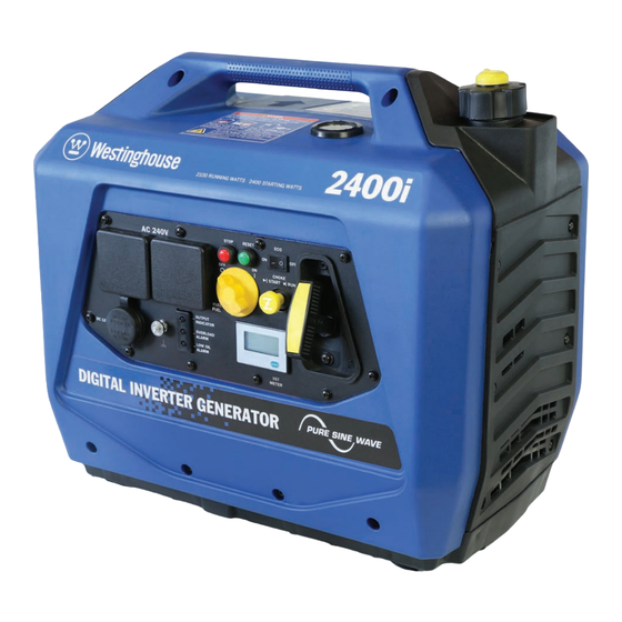
- Page 1 Digital Inverter Generator Instruction Manual 2400i...
- Page 2 DISCLAIMERS: All instructions, illustrations and specifications in this manual are based on the latest information available at the time of publishing. The illustrations used in this manual are intended as representative reference views only. Moreover, because of our continuous product improvement policy, we may modify information, illustrations or specifications to explain or exemplify a product, service or maintenance improvement.
- Page 3 CONGRATULATIONS ON PURCHASING A WESTINGHOUSE DIGITAL INVERTER GENERATOR Thank you for purchasing a Westinghouse portable generator. It is a high quality power product that will provide many years of safe and reliable service if properly operated and maintained. DANGER This manual contains important instructions for operating the generator. For your safety and that of others, be sure to read this manual thoroughly before operating the generator.
-
Page 5: Table Of Contents
CONTENTS SAFETY ..................................7 SAFETY DEFINITIONS ............................7 SAFETY SYMBOL DEFINITIONS ........................7 GENERAL SAFETY RULES ..........................8 SAFETY LABELS AND DECALS ........................10 UNPACKING ................................11 UNPACKING THE GENERATOR ........................11 ACCESSORIES ..............................11 FEATURES ................................12 MAIN GENERATOR COMPONENTS .......................12 CONTROL PANEL ............................14 OPERATION ................................15 BEFORE STARTING THE GENERATOR ......................15 CHECKING / ADDING ENGINE OIL AND FUEL ....................16 Checking and Adding Engine Oil ......................16 Checking and Adding Fuel ........................16... - Page 6 CONTENTS AIR FILTER MAINTENANCE ..........................26 Cleaning the Air Filter ..........................27 FUEL STRAINER MAINTENANCE ........................28 SPARK PLUG MAINTENANCE ........................29 SPARK ARRESTER MAINTENANCE .......................30 CLEANING THE GENERATOR .........................31 DRAINING THE FUEL ............................32 LONG-TERM STORAGE ..........................33 Storage Procedure for 1 – 3 Months ......................33 Storage Procedure for Greater than 3 Months ..................33 Removal from Storage ..........................33 DISMANTLING AND DISPOSAL ........................34...
-
Page 7: Safety
SAFETY SAFETY DEFINITIONS SAFETY SYMBOL DEFINITIONS The words DANGER, WARNING, CAUTION and Symbol Description NOTICE are used throughout this manual to highlight important information. Be certain that the meanings of these alerts are known to all who work Safety Alert Symbol on or near the equipment. -
Page 8: General Safety Rules
SAFETY GENERAL SAFETY RULES WARNING DANGER Petrol fuel liquid and vapours are extremely flammable and explosive Never use the generator in a location under certain conditions. that is wet or damp. Never expose the • Always refuel the generator generator to rain, snow, water spray outdoors, in a well-ventilated area. - Page 9 SAFETY WARNING Never operate the generator if: powered items overheat; electrical output drops; there are sparks, flames or smoke coming from the generator; or if the receptacles are damaged. Never attempt to connect more than one generator to the same electrical device, extension cord or fixed electrical installation.
-
Page 10: Safety Labels And Decals
SAFETY SAFETY LABELS The safety labels have specific positions and must be replaced if they are unreadable, damaged or missing. Figure 1 - Safety Labels... -
Page 11: Unpacking
ACCESSORIES Check the accessories against those shown in WARNING (Figure 2). If any parts are missing, please contact your local Westinghouse dealer. Always have assistance when lifting the generator. The generator is heavy; lifting it could cause bodily harm. A – 400 ml Bottle of SAE 15W-40 Engine Oil Avoid cutting on or near staples to B –... -
Page 12: Features
FEA TURES MAIN GENERATOR COMPONENTS 1 - Carry Handle 4 - Air Filter Access Cover 2 - Fuel Gauge 5 - Recoil Starter Handle 3 - Fuel Cap and Vent 6 - Control Panel Figure 3 - Main Generator Components (Front, Right Side & Top) - Page 13 FEA TURES 1 - Spark Plug Access Cover 4 - Oil Access Cover 2 - Muffler Access Cover 5 - Fuel Drain Hose 3 - Spark Arrester 6 - Fuel Drain Access Cover Figure 4 - Main Generator Components (Rear & Left Side)
-
Page 14: Control Panel
FEA TURES Voltage Engine Speed Figure 5 – Control Panel Features Run Time 1. 240-Volt AC, 15-Amp Outlets: Each outlet is 7. Fuel Control Switch: Turn the knob to the ON capable of delivering the generator’s peak output position before starting the generator. Select of 2,400 Watts (i.e. -
Page 15: Operation
OPERA TION BEFORE STARTING THE Weather – Never operate your generator outdoors during rain, snow or any combination of weather GENERATOR conditions that could lead to moisture collecting on, in or around the generator. Dry Surface – Always operate the generator on a Before starting the generator, review dry surface free of any moisture. -
Page 16: Checking / Adding Engine Oil And Fuel
OPERA TION CHECKING / ADDING ENGINE With the generator switched off and stationary on a horizontal surface, check the fuel level as indicated OIL AND FUEL on the fuel gauge. It is good practice to always fill the fuel tank before operating the generator. Before checking or adding engine oil Required Fuel –... -
Page 17: Starting The Generator
OPERA TION STARTING THE GENERATOR The primary touch points that the user needs to interact with when starting the generator are coloured yellow. Before starting the generator, review 1. Turn the fuel cap vent clockwise to the ON Safety on page 7. position (see Figure 7). -
Page 18: Eco Throttle Control
OPERA TION 4. Whilst holding the generator down with one hand, firmly grasp the recoil starter handle with your other hand and pull it slowly until you feel increased resistance. At this point, pull it briskly up and away from the generator (see Figure 10). Do not allow the starter handle to snap back against the engine, but instead return it gently to prevent starter damage. -
Page 19: Stopping The Generator
CYCLE 240-Volt AC devices can be connected either directly or via electrical extension cords into the All models within this range of Westinghouse 240-Volt AC outlet(s) on the generator’s control generators are portable, air-cooled, petrol- panel. Lift up the spring-loaded weather resistant... -
Page 20: 12-Volt Dc Loads
OPERA TION WARNING Never insert an automotive cigarette lighter into the 12-Volt DC outlet. The heated lighter may ignite the fuel causing an explosion or fire. Power Output and Demand There are two limits to the amount of electric power that the generator can usefully provide: (a) its total 240-Volt AC or 12-Volt DC electric power generating capacity or power output and (b) the electric current... -
Page 21: 240-Volt Ac Extension Cords
2,100 W for accordance with AS/NZS 3199:2007. the 2400i model. The above guidelines serve as approximations NOTICE only of determining the running and starting power DO NOT use extension cords with only 2-pin demands of 240-Volt AC devices. -
Page 22: 12 Volt Battery Charging
OPERA TION 12 VOLT BATTERY CHARGING away as possible from the generator due to the explosive gas hazard. There are two methods by which the generator can 6. Monitor the battery; stop charging if the battery be used to charge an external 12 Volt battery: gets hot to the touch and the electrolyte boils violently. -
Page 23: Transporting The Generator
OPERA TION TRANSPORTING THE 6. Insert the battery charger’s power supply plug into one of the generator’s 240-Volt AC outlet GENERATOR sockets and then switch the battery charger ON. The battery is now charging. Keep the battery as The generator should be stopped and both the fuel far away as possible from the generator due to control switch and fuel cap vent should be turned to the explosive gas hazard. -
Page 24: Maintenance
Alternatively, an authorised Westinghouse service dealer can carry out this work for a fee. Table 1: Basic Maintenance Schedule - Owner Performed... -
Page 25: Engine Oil Maintenance
MAINTENANCE Table 2 lists the more complicated maintenance tasks that are best performed by a qualified mechanic using specialised tools. It is recommended to engage an authorised Westinghouse service dealer to carry out this work. Table 2: Advanced Maintenance Schedule - Authorised Westinghouse Service Dealer Performed... -
Page 26: Adding Engine Oil
MAINTENANCE Adding Engine Oil 1. Always operate or maintain the generator on a flat surface. 2. Stop the engine, if running. 3. Let engine cool down for several minutes allowing crankcase pressure to equalise. 4. Remove the oil access cover on the rear of the generator (see Figure 14). -
Page 27: Cleaning The Air Filter
MAINTENANCE Cleaning the Air Filter The air filter must be cleaned after every 50 hours of use or 3 months (frequency should be increased if generator is operated in a dusty environment). 1. Turn off the generator and let it cool for several minutes if it’s been running. -
Page 28: Fuel Strainer Maintenance
MAINTENANCE FUEL STRAINER 9. Re-install the fuel strainer by hand inside the filter hole on top of the fuel tank (see Figure 23). MAINTENANCE Make sure it is fully inserted into the opening. Check and clean the fuel strainer after every 100 hours of use or 6 months. -
Page 29: Spark Plug Maintenance
MAINTENANCE SPARK PLUG MAINTENANCE Tools required – Spark plug socket wrench (included), spark plug gap tool or feeler gauge (not included) and wire brush (not included). The spark plug should be checked and cleaned after every 100 hours of use or 6 months and then replaced after 250 hours of use or every year. -
Page 30: Spark Arrester Maintenance
MAINTENANCE SPARK ARRESTER MAINTENANCE Tools required – Phillips head screwdriver (included) and wire brush (not included). Check and clean the spark arrester after every 100 hours of use or 6 months. 1. Stop the generator and let it cool for several minutes if it’s been running. -
Page 31: Cleaning The Generator
MAINTENANCE 7. If the spark arrester screen shows signs of wear such as rips, tears or large openings, it should be replaced. 8. Re-install the spark arrester components in the following order: a - Place spark arrester screen over the muffler exhaust pipe. -
Page 32: Draining The Fuel
MAINTENANCE DRAINING THE FUEL 7. Position a fuel storage container to collect fuel discharged from the drain hose (see Figure 34). Occasionally it may be necessary to drain all of the fuel out of the generator. For example, to remove contaminated or stale fuel or to prepare the generator for transport or storage. -
Page 33: Long-Term Storage
MAINTENANCE 11. Re-install the fuel drain access cover. 4. Press and hold down the engine stop button until the generator has ceased operating. 12. Turn the fuel control switch anti-clockwise to the OFF position. 5. Turn the fuel control switch to the OFF position. 13. -
Page 34: Dismantling And Disposal
Dismantling should only be carried out by a mechanically proficient person with access to proper tools or alternatively by your authorised Westinghouse service dealer for a fee. Before dismantling: 1. Stop the generator (see Stopping the Generator on page 19). -
Page 35: Troubleshooting
11. Check air filter element and clean if necessary. 12. Spark arrestor is dirty or 12. Check spark arrestor and clean if necessary. blocked. 13. If above possible causes 13. Take generator to an authorised Westinghouse are checked and eliminated, service dealer. generator may be faulty. - Page 36 Check running and starting power demands of total connected electrical load versus generator’s rating. If above possible causes Take generator to an authorised Westinghouse are checked and eliminated, service dealer. generator may be faulty.
- Page 37 OFF position and then re-connect electrical loads individually if possible. If only single load, check running and starting power demands versus generator’s rating. If above possible causes Take generator to an authorised Westinghouse are checked and eliminated, service dealer. generator may be faulty.
- Page 38 Drain fuel and refill with fresh fuel. contaminated. Air filter is dirty or blocked. Check air filter element and clean if necessary. If above possible causes Take generator to an authorised Westinghouse are checked and eliminated, service dealer. generator may be faulty.
-
Page 39: Specifications
SPECIFICA TIONS PARAMETER 2400i Type 1-Cylinder, 4-Stroke, Overhead Valve, Air Cooled Displacement (cm Speed (rpm) 3,200 ~ 5,000 Rated Power (kW / hp) 2.6 / 3.5 Oil Capacity (mL) Low Oil Shutdown Spark Plug Torch A5RTC Fuel Unleaded Petrol Fuel Tank Capacity (L) -
Page 40: Wiring Diagram
WIRING DIAGRAM 2400i WIRING DIAGRAM... -
Page 41: Warranty
W ARRANTY WARRANTY AGAINST DEFECTS serviced to schedule using genuine spare parts; altered or otherwise misused or damaged in any way. Proof of Purchase The Company shall not be responsible for any It is recommended that you keep a copy of the diagnosis, communication, dismantling, packing, original tax invoice together with this manual. - Page 42 NOTES...
- Page 44 W237 N2889 Woodgate Road, Unit B Pewaukee, WI 53072 USA www.westpropower.com.au © 2016 All rights reserved. Content may change without notice. Westpro Power Systems, a Westinghouse Electric Corporation licensee. August 2016 and Westinghouse are registered trademarks of Westinghouse Electric Corporation.
Need help?
Do you have a question about the 2400i and is the answer not in the manual?
Questions and answers