
Westinghouse iGen2300, iGen2600 - Inverter Generator Manual
- User manual (85 pages)
Advertisement
- 1 iGen TECHNICAL SPECIFICATIONS
- 2 SAFETY
- 3 UNPACKING
- 4 FEATURES
-
5
OPERATION
- 5.1 BEFORE STARTING THE INVERTER
- 5.2 POWER CORDS
- 5.3 INVERTER PARALLELING OPERATION
- 5.4 POWER OUTPUT AND DEMAND
- 5.5 INITIAL OIL FILL
- 5.6 ADDING/CHECKING ENGINE FLUIDS AND FUEL
- 5.7 CHECKING AND / OR ADDING ENGINE OIL
- 5.8 ADDING GASOLINE TO THE FUEL TANK
- 5.9 STARTING THE INVERTER
- 5.10 STOPPING THE INVERTER
- 5.11 USING EFFICIENCY MODE
- 5.12 RESETTING THE RESET BREAKER
-
6
MAINTENANCE
- 6.1 ENGINE OIL MAINTENANCE
- 6.2 CHECKING ENGINE OIL
- 6.3 ADDING ENGINE OIL
- 6.4 CHANGING ENGINE OIL
- 6.5 AIR FILTER MAINTENANCE
- 6.6 DRAINING THE FLOAT BOWL
- 6.7 SPARK PLUG MAINTENANCE
- 6.8 CLEANING THE SPARK ARRESTOR
- 6.9 CHECKING AND ADJUSTING VALVE LASH
- 6.10 CLEANING THE INVERTER
- 6.11 STORAGE
- 6.12 USING FUEL STABILIZER
- 7 TROUBLESHOOTING
- 8 iGen2300 EXPLODED VIEW
- 9 iGen2300 ENGINE VIEW
- 10 iGen2600 ENGINE VIEW
- 11 iGen2300 & iGen2600 SCHEMATIC
- 12 iGen2300 SPECIFICATIONS
- 13 iGen2600 SPECIFICATIONS
- 14 Documents / Resources
iGen TECHNICAL SPECIFICATIONS
| Model Number | Running Watts | Peak Watts | Fuel Tank Size (L/G) | Rated Speed (RPM) | Ignition Type | Spark plug | Engine Disp (cc) | Stroke X Bore | Oil Capacity (L) | Oil Type | THD |
| iGen2300 | 1800 | 2300 | 5.2/1.4 | 5400 | CDI | E6RTC | 79 | 49X43 | 0.35 | 10W30 | <5% |
| iGen2600 | 2200 | 2600 | 3.7/1.0 | 4800 | CDI | E6RTC | 98 | 52X46 | 0.35 | 10W30 | <5% |
NOTICE
Even with a carburetor modification, engine horsepower will decrease about 3.5% for each 300 meter (1,000 foot) increase in altitude. The effect of altitude on horsepower will be greater if no carburetor modification is made. A decrease in engine horsepower will decrease the power output of the generator. Contact our service team to order altitude kits.
SAFETY

Operating, servicing and maintaining this equipment can expose you to chemicals including engine exhaust, carbon monoxide, phosphates, and lead, which are known to the State of California to cause cancer and birth defects or other reproductive harm. To minimize exposure, avoid breathing exhaust, do not idle the engine except as necessary, service your equipment in a well-ventilated area and wear gloves or wash your hands frequently when servicing your equipment. For more information go to www.P65Warnings.ca.gov.

This manual contains important instructions for operating this inverter generator. For your safety and the safety of others, be sure to read this manual thoroughly before operating the generator. Failure to properly follow all instructions and precautions can cause you and others to be seriously hurt or killed.
SAFETY DEFINITIONS
The words DANGER, WARNING, CAUTION and NOTICE are used throughout this manual to highlight important information. Be certain that the meanings of these alerts are known to all who work on or near the equipment.
 This safety alert symbol appears with most safety statements. It means attention, become alert, your safety is involved! Please read and abide by the message that follows the safety alerts symbol.
Indicates a hazardous situation which, if not avoided, will result in death or serious injury.
Indicates a hazardous situation which, if not avoided, could result in death or serious injury.

Indicates a hazardous situation which, if not avoided, could result in minor or moderate injury.
NOTICE
Indicates a situation which can cause damage to the generator, personal property and/or the environment, or cause the equipment to operate improperly.
NOTE:
Indicates a procedure, practice or condition that should be followed in order for the inverter to function in the manner intended.
SAFETY SYMBOL DEFINITIONS
| Symbol | Description |
| Safety Alert Symbol |
 | Asphyxiation Hazard |
 | Burn Hazard |
 | Burst/Pressure Hazard |
 | Don't leave tools in the area |
 | Electrical Shock Hazard |
 | Explosion Hazard |
 | Fire Hazard |
 | Lifting Hazard |
 | Pinch-Point Hazard |
 | Read Manufacturer's Instructions |
 | Read Safety Messages Before Proceeding |
 | Wear Personal Protective Equipment (PPE) |
GENERAL SAFETY RULES

Never use the inverter in a location that is wet or damp. Never expose the inverter to rain, snow, water spray or standing water while in use. Protect the inverter from all hazardous weather conditions. Moisture or ice can cause a short circuit or other malfunction in the electrical circuit.
Never operate the inverter in an enclosed area. Engine exhaust contains carbon monoxide. Only operate the inverter outside and away from windows, doors and vents.

Voltage produced by the inverter could result in death or serious injury.
- Never operate the inverter in rain or a flood plain unless proper precautions are taken to avoid being subject to rain or a flood.
- Never use worn or damaged extension cords.
- Always have a licensed electrician connect the inverter to the utility circuit.
- Never touch an operating inverter if the inverter is wet or if you have wet hands.
- Never operate the inverter in highly conductive areas such as around metal decking or steel works.
- Always use grounded extension cords. Always use three-wire or double-insulated power tools.
- Never touch live terminals or bare wires while the inverter is operating.
- Be sure the inverter is properly grounded before operating.
Gasoline and gasoline vapors are extremely flammable and explosive under certain conditions.
- Always refuel the generator outdoors, in a well-ventilated area.
- Never remove the fuel cap with the engine running.
- Never refuel the inverter while the engine is running. Always turn engine off and allow the generator to cool before refueling.
- Only fill fuel tank with gasoline.
- Keep sparks, open flames or other form of ignition (such as match, cigarette, static electric source) away when refueling.
- Never overfill the fuel tank. Leave room for fuel to expand. Overfilling the fuel tank can result in a sudden overflow of gasoline and result in spilled gasoline coming in contact with HOT surfaces. Spilled fuel can ignite. If fuel is spilled on the inverter, wipe up any spills immediately. Dispose of rag properly. Allow area of spilled fuel to dry before operating the inverter.
- Wear eye protection while refueling.
- Never use gasoline as a cleaning agent.
- Store any containers containing gasoline in a well-ventilated area, away from any combustibles or source of ignition.
- Check for fuel leaks after refueling. Never operate the engine if a fuel leak is discovered.
Never operate the inverter if powered items overheat, electrical output drops, there is sparking, flames or smoke coming from the inverter, or if the receptacles are damaged.
Never use the inverter to power medical support equipment.
Always remove any tools or other service equipment used during maintenance from the inverter before operating.
NOTICE
Never modify the inverter.
Never operate the inverter if it vibrates at high levels, if engine speed changes greatly or if the engine misfires often.
Always disconnect tools or appliances from the inverter before starting.
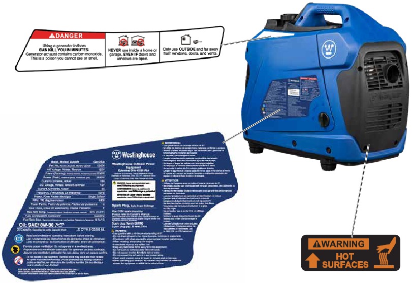
SAFETY LABELS AND DECALS IGEN2300 AND IGEN2600
UNPACKING
Always have assistance when lifting the inverter. The inverter is heavy; lifting it could cause bodily harm.
Avoid cutting on or near staples to prevent personal injury.
Tools required – box cutter or similar device.
- After opening box, Remove socket wrench, oil and funnel and save for later.
- Carefully cut two sides of the carton to remove the inverter.
WHAT COMES IN THE BOX
Spark Plug Socket Wrench (1)
Owners Manual (1)
Quick Start Guide (1)
Warranty Information (1)
Funnel (1)
.37 QT/.35 L Bottle of 10W-30 Oil (1)
FEATURES
INVERTER FEATURES IGEN2300 & IGEN2600

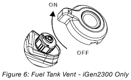
- Fuel Cap and Vent (vent: iGen2300 only): Open the vent to run the engine and close the vent when the engine is off.
- Control Panel: Contains the reset breaker, outlets and warning lights.
- LED Data Center: Indicates low oil, overload and output ready. Displays fuel level, power output, remaining run time, voltage and lifetime hours.
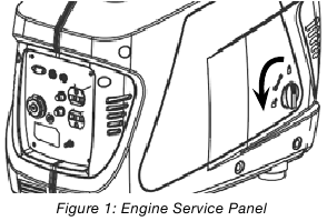
- Engine Service Panel: Turn knob to unlock and remove cover to service the oil, spark plug, and air filter.
- Recoil Handle: Pull to start the engine.
- Engine Control Switch: Sets the choke, turns the fuel on and off.
- Muffler and Spark Arrestor: Avoid contact until the engine is cooled down. The spark arrestor prevents sparks from exiting the muffler. It must be removed for servicing.
- Engine Cooling Vents: Helps move airflow in unit to regulate engine temperatures.
- Recoil Handle Protective Cover: Prevents pull cord wire from damaging inverter body.
- Oil Access Cover: Remove to service oil.
CONTROL PANEL FEATURES IGEN2300 AND IGEN2600

- 120-Volt, 20-Amp Duplex Outlet (NEMA 5-20R): The outlet is capable of carrying a maximum of 20 amps.
- USB Duplex: 5V DC that come in 1 amps and 2.1 amps.
- Reset Breaker: If the inverter is overloaded, the reset breaker will trip. The engine will continue to run, but there will be no output from the inverter. Unplug the devices and reduce the load. Push in the reset breaker to reset it.
- Efficiency Mode Switch: When turned to the ON position, the engine will sense the load needed and run at a slower RPM to save fuel.
- Ground Terminal: The ground terminal is used to externally ground the inverter.
- 12V DC Outlet: Provides 12-volt DC power up to 8 amps.
- LED Data Center: Indicates low oil, overload and output ready. Displays fuel level, power output, remaining run time, voltage, and lifetime hours.
- DC Breaker: Limits output of 12V DC outlet to 8A.
- Parallel Operation Outlets: These outlets are used for connecting an additional inverter generator (with same outlets) to achieve 30A output. A Westinghouse approved parallel operation cable kit (sold separate) is required for parallel operation.
LED Data Display

- LOW OIL INDICATOR
Description: Lights up red when unit is low or out of oil. Engine will not run when indicator is lit.
Recommended Action: When this light appears confirm engine is off, let the unit cool down, then add oil. Make sure to periodically check oil levels while filling to prevent overfilling. - OVERLOAD INDICATOR
Description: Red light flashes when the unit is close to overloading. If any more load is added when the light is flashing the electrical power will be cut to the receptacles and light will become a constant red.
Recommended Action: While the engine is running, disconnect all appliances and hit the RESET breaker on the panel. Reduce the amount of appliances before plugging back in. - OUTPUT READY INDICATOR
Description: The output ready indicator shows a green light when the generator is operating normally and producing electrical power to the receptacles. - FUEL LEVEL INDICATOR
Description: Displays estimated fuel level percentage. Four green lights indicate a full tank. One green light indicates the unit is almost out of fuel. For accurate fuel levels refer to "L" number in display. - ELECTRICAL POWER OUTPUT TO RECEPTACLES
Description: Displays percentage of power output to the receptacles. A red light will display next to the "100%" if the unit is close to being overloaded. For accurate power output refer to the "P" number in display. - AUTOMATIC ROTATING DATA NUMBER DISPLAY
![]()
Remaining Run Time (F): Displays time remaining with current fuel level and power output.
![]()
Power Output (P): Displays electrical power output to receptacles in kilowatts.
![]()
Fuel level (L): Displays current fuel level in liters.
![]()
Voltage (V): Displays current voltage output of generator.
![]()
Lifetime Hours: Displays the total run time of the generator.


OPERATION
BEFORE STARTING THE INVERTER
BEFORE STARTING THE INVERTER, REVIEW SAFETY SECTION.
Location Selection – Before starting the inverter, avoid exhaust and location hazards by verifying:
- You have selected a location to operate the inverter that is outdoors and well ventilated.
- You have selected a location with a level and solid surface on which to place the inverter.
- You have selected a location that is at least 15 feet (4.5 m) away from any building, other equipment or combustible material.
- If the inverter is located close to a building, make sure it is not located near any windows, doors and/or vents.
Using a generator indoors CAN KILL YOU IN MINUTES.
Generator exhaust contains carbon monoxide.
This is a poison you cannot see or smell.

NEVER use inside a home or garage, EVEN IF doors and windows are open.

Only use OUTSIDE and far away from windows, doors, and vents.
Avoid other generator hazards.
READ MANUAL BEFORE USE
Always operate the inverter on a level surface. Placing the inverter on non level surfaces can cause the inverter to tip over, causing fuel and oil to spill. Spilled fuel can ignite if it comes in contact with an ignition source such as a very hot surface.
NOTICE
Only operate the inverter on a solid, level surface. Operating the inverter on a surface with loose material such as sand or grass clippings can cause debris to be ingested by the inverter that could:
- Block cooling vents
- Block air intake system
Weather – Never operate your inverter outdoors during rain, snow or any combination of weather conditions that could lead to moisture collecting on, in or around the generator.
Dry Surface – Always operate the inverter on a dry surface free of any moisture.
No Connected Loads – Make sure the inverter has no connected loads before starting it. To ensure there are no connected loads, unplug any electrical extension cords that are plugged into the control panel receptacles.
NOTICE
Starting the inverter with loads already applied to it could result in damage to any appliance being powered off the inverter during the brief start-up period.
Grounding the iGen Inverters
Consult with your local municipalities for your grounding codes.
Be sure the inverter is properly connected to earth ground before operating.
High Altitude Operation
Engine power is reduced the higher you operate above sea level. Output will be reduced approximately 3.5% for every 1000ft of increased altitude from sea level. This is a natural occurrence and cannot be adjusted by engine. Increased exhaust emissions can also result due to increased fuel mixture. Other issues include hard starting, increased fuel consumption and spark plug fouling.
iGen2300 High Altitude Carburetor Kit Part Number: 140540
iGen2600 High Altitude Carburetor Kit Part Number: 140542
POWER CORDS
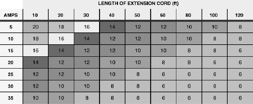
Using Extension Cords
Westinghouse Outdoor Power Equipment assumes no responsibility for the content within this table. The use of this table is the responsibility of the user only. This table is intended for reference only. The results produced by using this table are not guaranteed to be correct or applicable in all situations as the type and construction of cords are highly variable. Always check with local regulations and a licensed electrician prior to installing or connecting an electrical appliance.
Extension Cord Wire Gauge Size
INVERTER PARALLELING OPERATION
Never connect or remove the paralleling kit to the inverters with the inverters running. Make sure the parallel kit cables are in good working order. A faulty appliance or power cord can create a potential for electrical shock.
Use only approved Westinghouse parallel kit cables. Do not use the paralleling cord for any application other than inverter paralleling. For single generator operation, the parallel operation cable must be removed.
Note: Most motorized appliances require more than their electrical rating for startup. When an electric motor is started, the overload indicator (red) may come ON. This is normal if the overload indicator (red) goes off within 4 seconds. If the overload indicator (red) stays ON, consult Westinghouse service team.
- Connect the parallel operation kit cables between both inverters (kit and additional inverter sold separate). The leads on the parallel kit can go in either of the parallel operation outlets.
- Start each inverter and make sure the output indicator (green) on each inverter comes ON.
- Plug appliance into the parallel operation kit outlet.
To shut down: Turn off both inverters, then remove parallel operation cables.
POWER OUTPUT AND DEMAND
120 Volt AC devices have two different electric power demands that must be taken into consideration, namely the running power and the starting/peak power. Both are measured in Watts (typically abbreviated as "W").
The steady state continuous load is the running power demand and this is often marked on the device near its model number or serial number. Sometimes the device might only be marked with its voltage (i.e. 120 V) and current draw (e.g. 6 Amp or 6 A), in which case the running power demand in Watts can be obtained by multiplying the voltage times the current, e.g. 120 V × 6 A = 720 W.
Simple resistive 120-Volt AC devices such as incandescent bulbs, toasters, heaters, etc. have no extra power demand when starting, and so their starting power demands are the same as their running power demands.
More complex 120-Volt AC devices containing inductive or capacitive elements such as electric motors have a momentary extra power demand when starting, which can be up to seven times the running power demand or more. Manufacturers of such devices rarely publish this starting power demand and so it's often necessary to estimate it. A rule of thumb for devices fitted with an electric motor is to apply a starting power multiplier of 1.2 for small hand-held or portable devices and a value of 3.5 for larger stationary devices. For example, a 900 W angle grinder can be assumed to have a starting power demand of at least 1.2 × 900 W, which equals 1,080 W. Similarly, a 1,650 W air compressor can be assumed to have a starting power demand of at least 3.5 × 1,650 W, which equals 5,775 W.
To prevent overloading of the generator's 120-Volt AC system:
- Add up the running power demand of all the 120-Volt AC devices that will be connected to the generator at one time. This total must not be greater than the generator's specified running power output.
- Add up the running power demand again, but for the largest motor-driven device use the value of its starting power demand instead of its running power demand. This total must not be greater than the generator's specified starting power output.
- The total running power demand of all the devices that will be connected to any one of the generator's outlets must not exceed the generator's specified running power output.
INITIAL OIL FILL
BEFORE ADDING ENGINE OIL, REVIEW SAFETY SECTION.
NOTICE
Engine oil must be added when the inverter is on a flat, level surface, or an inaccurate reading may result. Do not overfill. If the engine is overfilled with oil, it can cause serious engine damage.
- Turn the locking knob on the engine access panel and set aside.
![]()
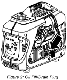
- Pull out oil access insert at the bottom of the case and clean the area around the oil fill/drain plug. Unscrew and remove plug.
![]()
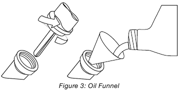
- Using the supplied funnel and oil, slowly pour oil into the engine. Stop frequently to make sure you do not overfill.
![]()
- Do not overfill, if oil level is too high, oil will drain out through the fill plug. See correct oil level in Figure 4.


ADDING/CHECKING ENGINE FLUIDS AND FUEL
BEFORE ADDING/CHECKING ENGINE FLUIDS AND FUEL, REVIEW SAFETY SECTION.
Filling the fuel tank with gasoline while the inverter is running can cause gasoline to leak and come in contact with hot surfaces that can ignite the gasoline.
Before starting the inverter, always check the level of:
- Engine oil
- Gasoline in the fuel tank
Once the inverter is started and the engine gets warm, it is not safe to add gasoline to the fuel tank or engine oil to the engine while the engine is running or the engine and muffler are hot.
CHECKING AND / OR ADDING ENGINE OIL
Internal pressure can build in the engine crankcase while the engine is running. Removing the oil fill plug/ dipstick while the engine is hot can cause extremely hot oil to spray out of the crankcase and can severely burn skin. Allow engine oil to cool for several minutes before removing the oil fill plug/dipstick.
The unit as shipped does not contain oil in the engine. You must add engine oil before starting the inverter for the first time. See Initial Oil Fill for instructions on checking engine oil level and the procedure for adding engine oil.
NOTICE
The engine does not contain engine oil as shipped. Attempting to start the engine without adding engine oil will permanently damage internal engine components.
The engine is equipped with a low oil shutdown switch. If the oil level becomes low, the engine may shut down and not start until the oil is filled to the proper level.
The owner of the inverter is responsible to ensure the proper oil level is maintained during the operation of the generator. Failure to maintain the proper oil level can result in engine damage.
ADDING GASOLINE TO THE FUEL TANK
Never refuel the inverter while the engine is running.
Always turn the engine off and allow the inverter to cool before refueling.
Avoid prolonged skin contact with gasoline. Avoid prolonged breathing of gasoline vapors.
Required Gasoline – Only use gasoline that meets the following requirements:
- Unleaded gasoline only
- Gasoline with maximum 10% ethanol added
- Gasoline with an 87 octane rating or higher
Filling the Fuel Tank – Follow the steps below to fill the fuel tank:
- Shut off the inverter.
- Allow the inverter to cool down so all surface areas of the muffler and engine are cool to the touch.
- Move the inverter to a flat surface.
- Clean area around the fuel cap.
- Remove the fuel cap by rotating counterclockwise.
NOTICE
Do not overfill the fuel tank. Spilled fuel will damage some plastic parts. - Slowly add gasoline into the fuel tank. Be very careful not to overfill the tank. The gasoline level should NOT be higher than the red ring.

- Install the fuel cap by rotating clockwise.

STARTING THE INVERTER
BEFORE STARTING THE INVERTER, REVIEW SAFETY SECTION.
For proper starting and operation of the inverter, make sure you review the inverter features and their descriptions.
Before attempting to start the inverter, verify the following:
- The engine is filled with engine oil (see Figure 4: Engine Oil Correct Level).
- The inverter is situated in a proper location (see Location Selection).
- The inverter is on a dry surface (see Weather and Dry Surface).
- All loads are disconnected from the inverter (see No Connected Loads).
- The inverter is properly grounded (see Grounding the Inverter).
Never use the inverter in a location that is wet or damp. Never expose the inverter to rain, snow, water spray or standing water while in use. Protect the inverter from all hazardous weather conditions. Moisture or ice can cause a short circuit or other malfunction in the electrical circuit.
Never operate the inverter in an enclosed area. Engine exhaust contains carbon monoxide. Only operate the inverter outside and away from windows, doors and vents.
Starting iGen2300 & iGen2600
- Check oil and fuel levels. If it is the first time starting make sure to add oil (see Initial Oil Fill).
- Turn the fuel tank vent to the ON position (iGen2300 only).
![]()
- Make sure the circuit breakers are properly set.
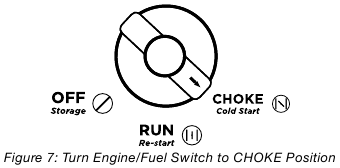
- For cold starting, turn the engine/fuel control switch to the CHOKE position (see Figure 7). NOTE: If you are re-starting turn knob to RUN.
![]()
- Firmly grasp and pull the recoil handle slowly until you feel increased resistance. At this point, apply a rapid pull while pulling out from the inverter.

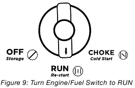
- As the engine starts and stabilizes, turn the choke switch back in to the RUN position.
![]()
- Plug in electronic devices.

STOPPING THE INVERTER
Normal Operation
During normal operation, use the following steps to stop your inverter:
- Remove any connected loads from the control panel receptacles.
- Allow the inverter to run at "no load" to reduce and stabilize engine and alternator temperatures.
- Move the engine control switch to the OFF position.
![]()
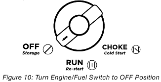
During an Emergency
If there is an emergency and the inverter must be stopped quickly, move the engine control switch to the OFF position immediately (see Figure 10).
USING EFFICIENCY MODE
The inverter is equipped with an efficiency mode switch to minimize fuel consumption. In efficiency mode, the inverter will sense the load and adjust the engine RPM to the current load requirements. Efficiency mode should be used only after the inverter has been warmed up to operating temperature.
- To turn on the efficiency mode, press the switch to the ON position).
- If no load is present, the inverter RPM will drop down to an idle speed.
- As a load is applied, the inverter will sense the load and engine RPM will increase according to the load applied.
- To run the inverter at maximum power and RPM, press the efficiency mode switch to the OFF position.
RESETTING THE RESET BREAKER
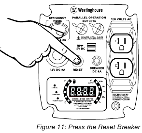
The inverter will trip the breaker and automatically disconnect from the load when the controls sense a predetermined overload condition. The engine will continue to run, but there will not be any electrical output.
- Turn off all devices and unplug them from the inverter.
- Determine the wattage required from the devices being powered by the inverter. Make sure the wattage required does not exceed the maximum output of the inverter.
- Press in the reset breaker to reset it.
![]()
- Plug the devices in to the inverter.
- Turn on the devices as needed.
MAINTENANCE
BEFORE PERFORMING MAINTENANCE ON THE INVERTER, REVIEW THE SAFETY SECTION, AS WELL AS THE FOLLOWING SAFETY MESSAGES.
Avoid accidentally starting the inverter during maintenance by removing the spark plug boot from the spark plug. For electric start inverters, also disconnect the battery cables from the battery (disconnect the black negative (-) cable first) and place the cables away from the battery posts to avoid arcing.
Allow hot components to cool to the touch prior to performing any maintenance procedure.
Internal pressure can build in the engine crankcase while the engine is running. Removing the oil fill plug/ dipstick while the engine is hot can cause extremely hot oil to spray out of the crankcase and can severely burn skin. Allow engine oil to cool for several minutes before removing the oil fill plug/dipstick.
Always perform maintenance in a well ventilated area. Gasoline fuel and fuel vapors are extremely flammable and can ignite under certain conditions.
 Avoid skin contact with engine oil or gasoline. Prolonged skin contact with engine oil or gasoline can be harmful. Frequent and prolonged contact with engine oil may cause skin cancer. Take protective measures and wear protective clothing and equipment. Wash all exposed skin with soap and water.
Failure to perform periodic maintenance or not following maintenance procedures can cause the inverter to malfunction and could result in death or serious injury.
NOTICE
Periodic maintenance intervals vary depending on inverter operating conditions. Operating the inverter under severe conditions, such as sustained highload, high-temperature, or unusually wet or dusty environments, will require more frequent periodic maintenance. The intervals listed in the maintenance schedule should be treated only as a general guideline.
Following the maintenance schedule is important to keep the inverter in good operating condition. The following is a summary of maintenance items by periodic maintenance intervals.
TABLE 1: MAINTENANCE SCHEDULE - OWNER PERFORMED
| Maintenance Item | Before Every Use | After First 20 Hours or First Month of Use | After 50 Hours of Use or Every 6 Months | After 100 Hour of Use or Every 6 Months | After 300 Hours of Use or Every Year |
| Engine Oil | Check Level | Change | Change | - | - |
| Cooling Features | Check/Clean | - | - | - | - |
| Air Filter | Check | - | Clean* | - | Replace |
| Spark Plug | - | - | - | Check/Clean | Replace |
| Spark Arrestor | - | - | - | Check/Clean | - |
*Service more frequently if operating in dry and dusty conditions
ENGINE OIL MAINTENANCE
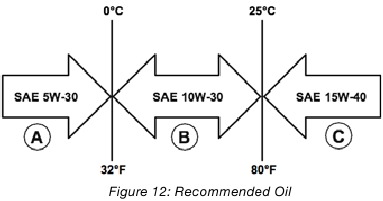
Engine Oil Specification
- Only use the engine oil specified in Figure 12.
![]()
- Only use 4-stroke/cycle engine oil. NEVER USE 2-STROKE/CYCLE OIL. Synthetic oil is an acceptable substitute for conventional oil.
CHECKING ENGINE OIL
NOTICE
Always maintain proper engine oil level. Failure to maintain proper engine oil level could result in severe damage to the engine and/or shorten the life of the engine.
Always use the specified engine oil. Failure to use the specified engine oil can cause accelerated wear and/ or shorten the life of the engine.
Engine oil level should be checked before every use.
- Always operate or maintain the inverter on a flat surface.
- Stop engine if running.
- Let engine sit and cool for several minutes (allow crankcase pressure to equalize).
- Remove the engine service panel to access the oil fill/ drain plug.
- With a damp rag, clean around the oil fill/drain plug.
- Remove the oil fill/drain plug.
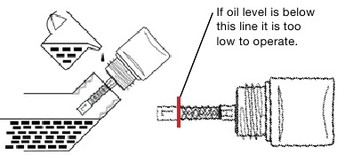
- Check oil level: When checking the engine oil, remove the oil fill/ drain plug.
- The oil level is acceptable if oil is visible at the bottom of the threads of the oil fill plug.
- If oil level is low, add to the correct level using the supplied oil fill bottle. Do not overfill the oil crankcase.
![]()
NOTICE
Engine oil must always be checked and added when the inverter is on a flat, level surface, or an inaccurate reading may result, causing serious engine damage.
ADDING ENGINE OIL
- Always operate or maintain the inverter on a flat surface.
- Stop engine if running.
- Let engine sit and cool for several minutes (allow crankcase pressure to equalize).
- Remove the engine service panel to gain access to the oil fill/drain plug.
- Thoroughly clean around the oil fill/drain plug.
- Remove the oil fill/drain plug.
- Select the proper engine oil as specified in Figure 12.
- Using the supplied oil funnel, slowly add engine oil to the engine. Stop frequently to check the oil level and avoid overfilling.
- Continue to add oil until the oil is at the correct level.
CHANGING ENGINE OIL
- Stop the engine.
- Let engine sit and cool for several minutes (allow crankcase pressure to equalize).
- Remove the engine service panel to gain access to the oil fill/drain plug.
- Remove oil access insert.
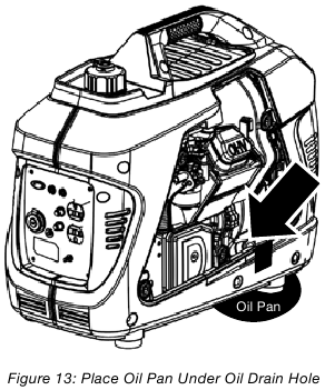
- Place oil pan (or suitable container) under the oil drain hole.
![]()
- With a damp rag, thoroughly clean around the oil fill/ drain plug.
- Tilt the inverter so the oil drains down through the hole in the bottom of the inverter into the container.
- Allow oil to completely drain.
- Fill crankcase with oil following the steps outlined in Adding Engine Oil.
- Dispose of used engine oil properly.
NOTICE
Never dispose of used engine oil by dumping the oil into a sewer, on the ground, or into groundwater or waterways. Always be environmentally responsible. Follow the guidelines of the EPA or other governmental agencies for proper disposal of hazardous materials. Consult local authorities or reclamation facility.
AIR FILTER MAINTENANCE
Never use gasoline or other flammable solvents to clean the air filter. Use only household detergent soap to clean the air filter.
Cleaning the Air Filter
The air filter must be cleaned after every 50 hours of use or 3 months (frequency should be increased if inverter is operated in a dusty environment).
- Turn off the inverter and let it cool for several minutes if running.
- Remove the engine service panel to gain access to the air filter.
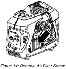
- Unscrew the air cleaner cover and tip the cover down.
![]()
- Remove the foam element from the air cleaner housing.
- Wash the foam air filter element by submerging the element in a solution of household detergent soap and warm water. Slowly squeeze the foam to thoroughly clean.
NOTICE
NEVER twist or tear the foam air filter element during cleaning or drying. Only apply slow but firm squeezing action. - Rinse in clean water by submerging the air filter element in fresh water and applying a slow squeezing action.
![]()
- Wash the foam air filter element by submerging the element in a solution of household detergent soap and warm water. Slowly squeeze the foam to thoroughly clean.
NOTICE
NEVER twist or tear the foam air filter element during cleaning or drying. Only apply slow but firm squeezing action. - Rinse in clean water by submerging the air filter element in fresh water and applying a slow squeezing action.
NOTICE
Never dispose of soap cleaning solution used to clean the air filter by dumping the solution into a sewer, on the ground, or into ground water or waterways. Always be environmentally responsible. Follow the guidelines of the EPA or other governmental agencies for proper disposal of hazardous materials. Consult local authorities or reclamation facility. - Dispose of used soap cleaning solution properly.
- Dry the air filter element by again applying a slow firm squeezing action.
- Place a small amount of oil in the center of the filter. Wring the filter to distribute the oil.
- Return the air filter element to its position in the air cleaner housing.
- Install the air cleaner cover, making sure the tabs lock into place.
- Install the engine service panel.

DRAINING THE FLOAT BOWL
- Remove the engine service panel to access the carburetor.
- Locate the clear plastic hose from the float that is exiting out the bottom of the inverter, and place a suitable container under it to catch the drained fuel.

- Loosen the float bowl drain screw (see Figure 16) until fuel is seen draining from the float bowl.
- Allow fuel to drain into the container, and then tighten the float bowl drain screw.
NOTICE
Never dispose of fuel by dumping fuel into a sewer, on the ground, or into groundwater or waterways. Always be environmentally responsible. Follow the guidelines of the EPA or other governmental agencies for proper disposal of hazardous materials. Consult local authorities or reclamation facility. - Install the engine service panel.

SPARK PLUG MAINTENANCE
The spark plug must be checked and cleaned after every 100 hours of use or 6 months and must be replaced after 300 hours of use or every year.
- Stop the inverter and let it cool for several minutes if running.
- Move the inverter to a flat, level surface.
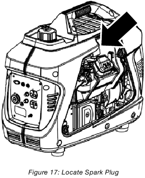
- Remove the engine service panel by unlocking knob and locate spark plug boot at top of engine.
![]()
- Remove the spark plug boot by firmly pulling the plastic spark plug boot handle directly away from the engine.
NOTICE
Never apply any side load or move the spark plug laterally when removing the spark plug. Applying a side load or moving the spark plug laterally may crack and damage the spark plug boot. - Clean area around the spark plug.
- Using the spark plug socket wrench provided, remove the spark plug from the cylinder head.

- Place a clean rag over the opening created by the removal of the spark plug to make sure no dirt can get into the combustion chamber.
- Inspect the spark plug for:
- Cracked or chipped insulator
- Excessive wear
- Spark plug gap of 0.032 in. (0.80 mm).
![]()

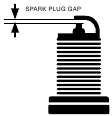
If the spark plug fails any one of the conditions listed above, replace the plug.
NOTICE
Only use the recommended spark plug. See chart below. Using a non- recommended spark plug could result in damage to the engine.
- Install the spark plug by carefully following the steps outlined below:
- Carefully insert the spark plug back into the cylinder head. Hand-thread the spark plug until it bottoms out.
- Using the spark plug socket wrench provided, turn the spark plug to ensure it is fully seated.
- Replace the spark plug boot, making sure the boot fully engages the spark plug's tip.
- Install the spark plug access cover.
Recommended Spark Plug Replacement:
| Westinghouse | Torch Spark plug | NGK | Bosch | AC Delco |
| 180532 | E6RTC | BPR6HS | WR7BC | R43FS |
CLEANING THE SPARK ARRESTOR
Check and clean the spark arrestor after every 100 hours of use or 6 months.
- Stop the inverter and let it cool for several minutes if running.
- Move the inverter to a flat, level surface.
- Remove the screws holding the muffler cover in place.

- Loosen the clamp holding the spark arrestor onto the muffler.
- Slide the spark arrestor band clamp off the spark arrestor screen.
- Pull the spark arrestor screen off the muffler exhaust pipe.
- Using a wire brush, remove any dirt and debris that may have collected on the spark arrestor screen.
- If the spark arrestor screen shows signs of wear (rips, tears or large openings in the screen), replace the spark arrestor screen.
- Install the spark arrestor components in the following order:
- Place spark arrestor screen over the muffler exhaust pipe. Push on the screen until it fully bottoms out.
- Place the spark arrestor band clamp over the screen and tighten with a flathead screwdriver
- Replace the discharge gate.

CHECKING AND ADJUSTING VALVE LASH
Checking and adjusting valve lash must be done when the engine is cold.
- Remove the rocker arm cover and carefully remove the gasket. If the gasket is torn or damaged, it must be replaced.
- Remove the spark plug so the engine can be rotated more easily.
- Rotate the engine to top dead center (TDC) of the compression stroke. Looking through the spark plug hole, the piston should be at the top.
- Both the rocker arms should be loose at TDC on the compression stroke. If they are not, rotate the engine 360°.
- Insert a feeler gauge between the rocker arm and the valve stem and check for clearance (see Figure 20). See Table 2 for valve lash specifications
![]()
- Valve Stem,
- Feeler Gauge Area
- Rocker Arm,
- Jam Nut,
- Adjusting Nut,
- Push Rod

Table 2: Standard Valve Lash
| Intake Valve | Exhaust Valve | |
| Valve Lash | .0023-.0039in (.06-.10mm) | .0031-.0048in (.08-.12mm) |
| Bolt Torque | 8-12N.m | 8-12N.m |
- If an adjustment is required, hold the adjusting nut and loosen the jam nut.
- Turn the adjusting nut to obtain the correct valve lash. When the valve lash is correct, hold the adjusting nut and tighten the jam nut to 106 in-lb (12 N•m).
- Recheck the valve lash after tightening the jam nut.
- Perform this procedure for both the intake and exhaust valves.
- Install the rocker arm cover, gasket and spark plug.
CLEANING THE INVERTER
It is important to inspect and clean the inverter before every use.
Clean All Engine Air Inlet and Outlet Ports – Make sure all engine air inlet and outlet ports are clean of any dirt and debris to ensure the engine does not run hot.
STORAGE
When preparing the generator for storage, allow the unit to cool for 30 minutes then follow the guidelines below. Always store the generator standing on its feet. Never store the unit on its side or in a vertical position.
Never store an inverter with fuel in the tank indoors or in a poorly ventilated area where the fumes can come in contact with an ignition source such as a:
- pilot light of a stove, water heater, clothes dryer or any other gas appliance; or
- spark from an electric appliance.
NOTICE
Gasoline stored for as little as 3 weeks can go bad in small engine carburetors, causing gum, varnish and corrosive buildup in fuel lines, fuel passages, and the engine. This corrosive buildup restricts the flow of fuel, preventing an engine from starting after a prolonged storage period. Fuel stabilizers also offer limited relief for the longevity of gasoline. As an additive, it is not reliable for long term storage of your generator and may still lead to engine corrosion.
USING FUEL STABILIZER
Fuel gets old, oxidizes, and breaks down over time. Adding a fuel stabilizer (not included) extends the usable life of fuel and helps prevent deposits from forming that can clog the fuel system. Follow fuel stabilizer manufacturer's directions for correct ratio of stabilizer to fuel.
- Mix fuel stabilizer and gasoline prior to filling the tank by using a gas can or other approved fuel container and shaking gently to combine.
NOTE: To control the amount of fuel stabilizer being added to the engine, always mix fuel stabilizer with gasoline before fueling the tank rather than adding fuel stabilizer directly into the generator's fuel tank. - Replace and secure the fuel tank cap.
- Start and run the engine for at least 5 minutes to allow stabilizer to treat the entire fuel system.
| Storage Time | Prior to Storing |
| Less than 2 months |
|
| 2 months to 1 year |
|
| 1 year or more |
|
| NOTE: If storing gasoline in suitable container for later use, make sure gasoline has been treated with fuel stabilizer according to stabilizer manufacturer's instructions. | |
TROUBLESHOOTING
Before attempting to service or troubleshoot the inverter, the owner or service technician must first read the owner's manual and understand and follow all safety instructions. Failure to follow all instructions may result in conditions that can lead to voiding of the EPA certification or product warranty, serious personal injury, property damage or even death.
| PROBLEM | POTENTIAL CAUSE | SOLUTION |
| Engine is running, but no electrical output. |
|
|
| Engine will not start or remain running while trying to start. |
|
|
| Inverter suddenly stops running. |
|
|
| Engine runs erratic; does not hold a steady RPM. |
|
|
iGen2300 EXPLODED VIEW

| NO. | PART. | DESCRIPTION |
| 1 | 300686 | ENGINE |
| 2 | 300687 | MUFFLER BAFFLE |
| 3 | 300688 | RIGHT FRAME |
| 4 | 301000 | FLOOR |
| 5 | 300689 | LEFT FRAME |
| 6 | 300690 | RIGHT SIDE PANEL |
| 7 | 300691 | AFTER THE PANEL COVER |
| 8 | 110189 | CROSS SLOTTED HEAD SCREW M6X16 |
| 9 | 301001 | DC VOLTAGE STABILIZER |
| 10 | 120505 | BOLT M6X12 |
| 11 | 100548 | NUT M6 |
| 12 | 150532 | CROSS RECESSED PAN HEAD SCREW M5×12 |
| 13 | 300692 | KNOB SCREW M4X16 |
| 14 | NA | PULL PLATE SCREW |
| 15 | 300636 | LOCKING M6 |
| 16 | 160028 | SQUARE NUT M6 |
| 17 | 100507 | SIDE PANEL BOTTOM SCREWS |
| 18 | NA | SCREW ST4.2X13 |
| 19 | NA | STEEL BALL M6 |
| 20 | 190888 | BEARING HOLDER M5 |
| 21 | 300693 | WIND HOOD |
| 22 | NA | CABLE GUIDE |
| 23 | 300694 | HANDLE DECORATIVE PIECE |
| 24 | 300634 | VIBRATION ISOLATION PAD FUEL TANK |
| 25 | 300695 | DAMPER |
| 26 | 300696 | RUBBER FOOT |
| 27 | 300635 | VIBRATION ISOLATION PAD FUEL TANK |
| 28 | 300697 | VIBRATION ISOLATION PAD FRAME |
| 29 | 301002 | RUBBER SPLASH GUARD |
| 30 | 300689 | PANEL ASSEMBLY |
| 31 | NA | USB DUST COVER |
| 32 | 120553 | GROUNDING WIRE |
| 33 | NA | EARTH WIRE |
| 34 | 300699 | CHOKE RUN OFF KNOB |
| 35 | 300700 | CABLE TRAY |
| 36 | 300701 | FUEL SWITCH BRACKET |
| 37 | 170507 | STARTER GRIP |
| 38 | 150513 | FUEL CAP |
| 39 | 150514 | FUEL LEVEL SCREEN |
| 40 | 300702 | FUEL TANK |
| 41 | NA | FUEL PIPE |
| 42 | 300722 | SPRING |
| 43 | 300703 | FUEL SWITCH |
| 44 | NA | CHOKE LINE |
| 45 | 150508 | FUEL PIPE CLAMP M9X.08 |
| 46 | NA | FUEL PIPE CLAMP M11X.08 |
| 47 | 180577 | FLAT WASHER 3.2 |
| 48 | 100621 | TOOTH TYPE GASKET |
| 49 | NA | OPEN RING |
| 50 | 120506 | INVERTER |
| 51 | 301011 | MAIN WIRE HARNESS |
| 52 | 170515 | RECOIL ANCHOR |
| 53 | 100593 | FUEL FILTER |
| 54 | 130536 | ROTOR BOLT M6×16 |
| 55 | 300704 | MOTOR INLET COVER |
| 56 | 191885 | DUST COVER |
| 57 | NA | FLAT MAT |
| 58 | NA | SEAL RING |
| 59 | 180689 | RUBBER |
| 60 | 300705 | FIXED DISK |
| 61 | NA | FUEL TANK SEALING RING |
| 62 | 300706 | PROTECTIVE PLASTIC TOP |
| 63 | 300707 | LEFT PANEL |
| 64 | 301009 | LEFT PANEL SCREW M4X10 |
| 65 | NA | FUEL TANK BRACE |
| 66 | NA | INVERTER HOOD |
| 67 | 300708 | RIGHT PANEL KNOB |
| 68 | 300709 | WASHER 37X22X3 |
| 69 | 300710 | U-CLIP |
| 70 | 120518 | BOLT M5×16 |
| 71 | 180625 | FUEL PIPE CLAMP Ф12 |
| 72 | 100060 | NUT M6 |
| 73 | 300262 | SEALING WASHER |
| 74 | NA | FUEL SENSOR CLAMP |
| 75 | 300711 | WIND COVER RING |
| 76 | 150532 | CROSS RECESSED PAN HEAD SCREW M5×12 |
| 77 | NA | STATOR ASSEMBLY |
| 78 | NA | ROTOR ASSEMBLY |
| 79 | NA | THE MOTOR FAN |
| 80 | NA | MUFFLER HOUSING |
| 81 | NA | SEALING RING WITH MUFFLER |
| 82 | NA | MOTOR ENCLOSURE |
| 83 | 100636 | BOLT M6X30 |
| 84 | NA | FUEL PIPE |
| 85 | NA | PLUG |
| 86 | 301003 | GASOLINE SENSOR |
| 87 | 130139 | 120V AC DUPLEX OUTLETS |
| 88 | 300795 | PARALLEL 2 PORT OUTLETS |
| 89 | 190656 | USB SOCKET |
| 90 | 190602 | EFFICIENCY MODE SWITCH |
| 91 | 301005 | 8A THERMAL PROTECTOR |
| 92 | 301012 | 12V DC POWER SOCKET |
| 93 | 191600 | WATERPROOF CAP FOR 8A BREAKER |
| 94 | NA | GROUNDING BOLT |
| 95 | 190657 | INVERTER RESET BUTTON |
| 96 | 301004 | DATA CENTER BLACK CONNECTIONS |
| NA | NA | CIGARETTE LIGHTER DUST COVER |
| NA | NA | CONTROL PANEL FACE |
Westinghouse Generator Accessories (call to order)
| 210050 | GENERATOR COVER |
| 30114A | GENERATOR PLUG ADAPTER: 30A 120V L14-30P TO TT-30R |
| 304PC | 30A INVERTER GENERATOR PARALLEL CORD |
| 507PC | 50A INVERTER GENERATOR PARALLEL CORD |
iGen2300 ENGINE VIEW

iGen2300 ENGINE PART NO.
| NO. | PART. | DESCRIPTION |
| 1 | NA | CRANKCASE |
| 2 | 260098 | SWITCH ASSEMBLY, OIL LEVEL |
| 3 | 120505 | BOLT M6X12 |
| 4 | NA | CLAMPER CORD |
| 5 | NA | OIL SEAL |
| 6 | NA | BALL BEARING |
| 7 | NA | CRANKSHAFT |
| 8 | 301007 | PISTON |
| 9 | 191750 | SCRAPER RING SET |
| 10 | 260090 | PIN, PISTON |
| 11 | NA | CLIP, PISTON |
| 12 | 301008 | ROD ASSEMBLY CONNECTING |
| 13 | 260088 | LIFTER, VALVE |
| 14 | 260087 | CAMSHAFT ASSEMBLY |
| 15 | 180703 | CRANKCASE PIN DOWEL |
| 16 | NA | CRANKCASE GASKET |
| 17 | NA | CRANKCASE ASSEMBLY |
| 18 | 180558 | DIPSTICK |
| 19 | 260084 | CYLINDER HEAD GASKET |
| 20 | 260083 | CYLINDER HEAD |
| 21 | 180532 | SPARK PLUG |
| 23 | 260091 | EXHAUST VALVE ROCKER ASSEMBLY |
| 24 | 260090 | ROCKSHAFT |
| 25 | 260094 | INLET VALVE SPRING SEAT |
| 26 | 260097 | INTAKE VALVE LG CIRCLE |
| 27 | 260096 | VALVE EXHAUST |
| 28 | 260095 | SPRING, VALVE |
| 29 | 260093 | SEAT, VALVE SPRING, IN |
| 30 | 260092 | VALVE LOCK CLAMP |
| 31 | 300188 | BOLT, STUD M6X92 |
| 32 | NA | BOLT, STUD M6X32 |
| 33 | 260089 | ROD, PUSH |
| 34 | 100702 | BOLT M6X50 |
| 35 | 190611 | CYLINDER HEAD GASKET |
| 36 | 191003 | CYLINDER HEAD CAP |
| 37 | NA | CYLINDER HEAD SHROUD |
| 38 | 190525 | MAGNETO IGNITION |
| 39 | NA | STRIPPER RUBBER |
| 40 | 180567 | BOLT M6X20 |
| 41 | NA | FLYWHEEL |
| 42 | 100006 | NUT, FLYWHEEL M12 |
| 43 | 260020 | RECOIL STARTER ASSEMBLY |
| 44 | 180786 | STEP MOTOR SCREWS M3X8 |
| 45 | 130536 | BOLT M6X16 |
| 46 | 191004 | CONNECTION BLOCK GASKET |
| 47 | 140521 | CARBURETOR THERMAL INSULATION |
| 48 | 140520 | CARBURETOR GASKET |
| 49 | 140524A | CARBURETOR ASSEMBLY |
| 50 | 180577 | FLAT WASHER Ф3.2 |
| 51 | 180782 | SPRING WASHER Ф3.2 |
| 52 | NA | STEPPER MOTOR PROTECTIVE COVER |
| 53 | 140523 | AIR CLEANER GASKET |
| 54 | 190310 | AIR CLEANER ASSEMBLY |
| 54.1 | 160503 | AIR CLEANER ELEMENT |
| 55 | 100548 | NUT M6 |
| 56 | 140522 | STEPPER MOTOR |
| 57 | NA | TUBE, BREATHER |
| 58 | NA | MUFFLER COVER |
| 59 | NA | CLIP, MUFFLER COVER |
| 60 | 110507 | MUFFLER ASSEMBLY |
| 61 | 301006 | IGNITION COIL |
| 62 | 110506 | EXHAUST GASKET (INTAKE) |
| 63 | 150518 | CLIP, BREATHER TUBE Ф10.5 |
| 64 | NA | CYLINDER HEAD COVER BREATHING BOARD |
| 65 | NA | GASKET |
| NA | 191006 | SPARK PLUG TOOL WRENCH (LONG) |
| NA | 210071 | .35L OIL BOTTLE |
| NA | M02000 | MAINTENANCE KIT (SOLD SEPARATE) |
| NA | 140540 | HIGH ALTITUDE CARBURETOR ASSEMBLY (SOLD SEPARATE) |
| NA | 300502 | SPARK ARRESTOR |
iGen2600 EXPLODED VIEW

iGen2600 EXPLODED VIEW PART NO.
| NO. | PART. | DESCRIPTION |
| 1 | 300713 | ENGINE |
| 2 | 300687 | MUFFLER BAFFLE |
| 3 | 300688 | THE RIGHT FRAME |
| 4 | 301000 | FLOOR |
| 5 | 300716 | THE LEFT FRAME |
| 6 | 300317 | THE RIGHT PANEL |
| 7 | 300691 | PANEL BACK COVER |
| 8 | 110189 | CROSS SLOTTED HEAD SCREW M6X16 |
| 9 | 301001 | DC VOLTAGE STABILIZER |
| 10 | 120505/120539 | BOLT M6X12 |
| 11 | 100219 | NUT M6 |
| 12 | 150532 | CROSS SLOTTED HEAD SCREW M5X12 |
| 13 | 300692 | SCREW M4X16 |
| 14 | NA | SCREW Φ3X15MM |
| 15 | 100514 | J CLIP |
| 16 | NA | NUT 16X16X5_M6 |
| 17 | 100507 | SCREW M6X16 |
| 18 | NA | SCREW ST4.2X13 |
| 19 | NA | STEEL BALL Φ6 |
| 20 | NA | BEARING HOLDER Φ5 |
| 21 | 300693 | WIND HOOD |
| 22 | NA | CABLE PLATE |
| 23 | 300694 | HANDLE DECORATIVE PIECE |
| 24 | 300634 | VIBRATION ISOLATION PAD |
| 25 | 300695 | DAMPER |
| 26 | 300696 | RUBBER FOOT |
| 27 | 300635 | VIBRATION ISOLATION PAD |
| 28 | 300697 | VIBRATION ISOLATION PAD FRAME |
| 29 | 301002 | RUBBER SPLASH GUARD |
| 30 | 301010 | CONTROL PANEL ASSEMBLY |
| 31 | NA | USB DUST COVER |
| 32 | 120553 | SHORT WIRES |
| 33 | NA | GROUND WIRE |
| 34 | 300699 | KNOB |
| 35 | 300700 | CABLE TRAY |
| 36 | 300701 | OIL SWITCH BRACKET |
| 37 | 170507 | STARTER GRIP |
| 38 | 150503 | THE CAP |
| 39 | 150509 | SCREEN |
| 40 | 150511 | THE FUEL TANK |
| 41 | NA | FUEL PIPE |
| 42 | 300722 | SPRING |
| 43 | 300703 | OIL SWITCH |
| 44 | NA | LASSO |
| 45 | NA | FUEL PIPE CLAMP M9×0.8 |
| 46 | 100620 | FUEL PIPE CLAMP M11×0.8 |
| 47 | 180577 | FLAT MAT M3.2 |
| 48 | 100621 | TOOTH WASHER M6 |
| 49 | NA | OPEN RING M9 |
| 50 | 120500 | INVERTER |
| 51 | 301011 | DEPUTY WIRING HARNESS |
| 52 | 170515 | RECOIL ANCHOR |
| 53 | 300067 | FILTER |
| 54 | 130536 | BOLT M6X16 |
| 55 | 300704 | MOTOR INLET COVER |
| 56 | 191885 | DUST COVER |
| 57 | NA | FLAT MAT M4 |
| 58 | 150544 | SEAL RING |
| 59 | NA | TUBING PROTECTIVE SLEEVE |
| 60 | 300705 | FIXED DISK |
| 61 | NA | SEALING RING |
| 62 | 300706 | PROTECTIVE PLASTIC TOP |
| 63 | 300707 | THE LEFT PANEL |
| 64 | 301009 | LEFT PANEL SCREW M4X10 (BLACK) |
| 65 | NA | STENTS |
| 66 | NA | INVERTER HOOD |
| 67 | 300708 | A KNOB |
| 68 | 300709 | FLAT MAT 37X22X3 |
| 69 | 300710 | U-CLIP |
| 70 | NA | BOLT M5X16 |
| 71 | 180625 | FUEL PIPE CLAMP Ф12 |
| 72 | 100060 | NUT M6 |
| 73 | 300262 | SEALING WASHER |
| 74 | 150542 | CLAMP |
| 75 | 300711 | WIND COVER |
| 76 | 150532 | PAN HEAD SCREW M5X12 |
| 77 | NA | MOTOR STATOR ASSEMBLY |
| 78 | NA | MOTOR ROTOR ASSEMBLY |
| 79 | NA | THE MOTOR FAN |
| 80 | NA | MUFFLER HOUSING |
| 81 | 100511 | RUBBER MUFFLER BOOT |
| 82 | NA | MOTOR ENCLOSURE |
| 83 | 300173 | BOLT M6X30 |
| 84 | 190317 | CARBON TANK |
| 85 | NA | CARBON TANK BREATHER TUBE |
| 86 | NA | CARBON TANK BREATHER TUBE |
| 87 | NA | CARBON TANK BRACKET |
| 88 | 190316 | GASOLINE SENSOR |
| 89 | 150533 | PLUG |
| 90 | 190602 | EFFICIENCY MODE SWITCH |
| 91 | 300795 | PARALLEL PORTS |
| 92 | 301013 | USB SOCKET |
| 93 | 130139 | 120V AC DUPLEX |
| 94 | 301005 | 8A THERMAL PROTECTOR |
| 95 | 191600 | WATERPROOF CAP |
| 96 | NA | GROUNDING BOLT |
| 97 | 190657 | VOLTAGE RESET SWITCH |
| 98 | 301014 | DATA CENTER BLACK CONNECTIONS |
| 99 | 301012 | 12V DC POWER SOCKET |
| NA | NA | CIGARETTE LIGHTER DUST COVER |
Westinghouse Generator Accessories (call to order)
| 210050 | GENERATOR COVER |
| 30114A | GENERATOR PLUG ADAPTER: 30A 120V L14-30P TO TT-30R |
| 304PC | 30A INVERTER GENERATOR PARALLEL CORD |
| 507PC | 50A INVERTER GENERATOR PARALLEL CORD |
iGen2600 ENGINE VIEW

iGen2600 ENGINE PART NO.
| NO. | PART. | DESCRIPTION |
| 1 | NA | CRANKCASE |
| 2 | 260098 | SWITCH ASSEMBLY, OIL LEVEL |
| 3 | 120505 | BOLT M6X12 |
| 4 | NA | CLAMPER CORD |
| 5 | NA | OIL SEAL |
| 6 | NA | BALL BEARING |
| 7 | NA | CRANKSHAFT |
| 8 | NA | PISTON |
| 9 | NA | SCRAPER RING SET, PISTON |
| 10 | NA | PIN, PISTON |
| 11 | NA | CLIP, PISTON |
| 12 | 301008 | ROD ASSEMBLY., CONNECTING |
| 13 | 260088 | LIFTER, VALVE |
| 14 | 260087 | CAMSHAFT ASSEMBLY |
| 15 | 180703 | CRANKCASE PIN DOWEL |
| 16 | NA | GASKET, MOLD ASSEMBLING |
| 17 | NA | COVER ASSEMBLY, CRANKCASE |
| 18 | 180558 | DIPSTICK |
| 19 | 260084 | GASKET, CYLINDER HEAD |
| 20 | 191001 | CYLINDER HEAD |
| 21 | 180532 | SPARK PLUG |
| 22 | NA | INLET VALVE ROCKER ASSEMBLY |
| 23 | 260091 | EXHAUST VALVE ROCKER ASSEMBLY |
| 24 | 260090 | ROCKSHAFT |
| 25 | 260094 | INLET VALVE SPRING SEAT |
| 26 | 190998 | VALVE, IN |
| 27 | 260096 | VALVE EXHAUST |
| 28 | 260095 | SPRING, VALVE |
| 29 | 260093 | SEAT, VALVE SPRING, IN |
| 30 | 260092 | VALVE LOCK CLAMP |
| 31 | 300188 | BOLT, STUD M6X92 |
| 32 | NA | BOLT, STUD M6X32 |
| 33 | 260089 | ROD, PUSH |
| 34 | 100702 | BOLT M6X50 |
| 35 | 190611 | PACKING, HEADCOVER |
| 36 | 191003 | COVER COMP, CYLINDER HEAD |
| 37 | NA | CYLINDER HEAD SHROUD |
| 38 | 190525 | MAGNETO IGNITION |
| 39 | NA | RUBBER SEAL |
| 40 | 180567 | BOLT M6X20 |
| 41 | NA | FLYWHEEL |
| 42 | NA | NUT, FLYWHEEL M12 |
| 43 | 260020 | RECOIL STARTER ASSEMBLY |
| 44 | 180786 | CROSS RECESSED PAN HEAD BOLTS M3X8 |
| 45 | 130536 | BOLT M6X16 |
| 46 | 191004 | CONNECTION BLOCK GASKET |
| 47 | 140521 | CARBURETOR THERMAL INSULATION, |
| 48 | 140520 | CARBURETOR GASKET |
| 49 | 140511 | CARBURETOR ASSEMBLY |
| 50 | 180577 | FLAT WASHER Ф3.2 |
| 51 | 180782 | SPRING WASHER Ф3.2 |
| 52 | NA | VENT |
| 53 | 140523 | AIR CLEANER GASKET |
| 54 | 191002 | AIR CLEANER ASSEMBLY |
| 54.1 | 160503 | AIR CLEANER ELEMENT |
| 55 | 100548 | NUT M6 |
| 56 | 140522 | STEPPER MOTOR |
| 57 | NA | TUBE,BREATHER |
| 58 | NA | MUFFLER COVER |
| 59 | NA | MUFFLER COVER CLIP |
| 60 | 110505 | MUFFLER ASSEMBLY |
| 61 | 180525 | IGNITION COIL |
| 62 | 110506 | EXHAUST GASKET (INTAKE) |
| 63 | 150518 | CLIP, BREATHER TUBE Ф10.5 |
| 64 | NA | CYLINDER HEAD COVER BREATHING BOARD. |
| 65 | NA | GASKET GASKET. |
| 66 | 300712 | SECONDARY AIR SUPPLY VALVE |
| 67 | 300728 | AIR SUPPLY GASKET |
| 68 | 120537 | BOLT M5X12 |
| NA | 140542 | HIGH ALTITUDE CARBURETOR ASSEMBLY (SOLD SEPARATE) |
| NA | NA | STEPPER MOTOR PROTECTIVE COVER |
| NA | 191006 | SPARK PLUG TOOL WRENCH (LONG) |
| NA | M02000 | MAINTENANCE KIT (SOLD SEPARATE) |
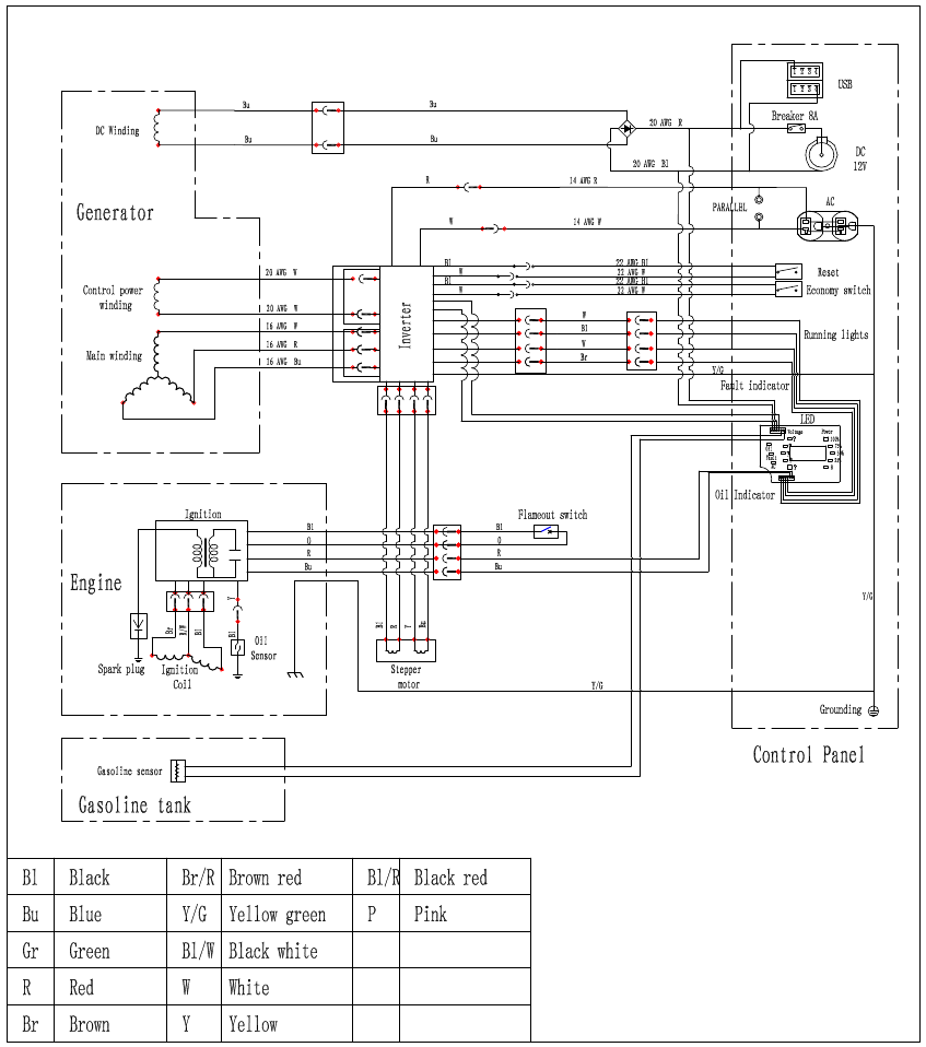
iGen2300 & iGen2600 SCHEMATIC
iGen2300 SPECIFICATIONS
| Gasoline Peak Watts | 2300 |
| Gasoline Running Watts | 1800 |
| Peak Amps at 120V | 19.1 amps |
| Running Amps at 120V | 15 amps |
| AC Voltage | 120 Volts |
| DC Voltage | 5 Volts |
| AC Frequency | 60 Hz |
| Parallel Capable with Westinghouse 30A or 50A cords (sold separate) | Yes |
| Engine Horse Power (HP) | 3 HP |
| Total Harmonic Distortion (THD) | <3% |
| Automatic Voltage Regulator (AVR) | Yes |
| Starting System | Recoil |
| Battery | No |
| Engine Displacement | 79cc |
| Engine Brand | Westinghouse |
| Engine Type | OHV 4 Stroke |
| Engine Speed | Variable |
| Engine RPM | Max 5400 |
| Operational Volume | as low as 52 dBA |
| Spark Plug (included) | Torch E6RTC |
| Carburetor Kit Required to Operate at Altitude | Yes |
| Altitude Carburetor Kit Number (sold separate) | 140540 |
| Economy Mode Switch | Yes |
| Built-in Inverter | Yes |
| Engine Lubrication | Splash |
| Recommended Oil | SAE 10W30 |
| Oil Bottle Size (included) | .37 qt. (11.8 oz.) |
| Oil Capacity (Quarts/Ounces) | .37 qt. (11.8 oz.) |
| Low Oil Shutdown | Automatic |
| Fuel Type | Unleaded Gasoline, 10% Ethanol or less |
| Fuel Shut Off | Manual |
| Fuel Tank Material | Plastic |
| Fuel Tank Capacity (Gallons/Liters) | 1.4 gal. (5.3 L) |
| *Run Time at %25 Load (hrs.) | 12 hrs. |
| *Run Time at %50 Load (hrs.) | 10 hrs. |
| Gasoline Fuel Gauge | Yes |
| Choke type | Manual |
| AC Outlets | (1) Duplex 120V 20A (5-20R) |
| DC Outlets | (1) 12V DC 8A (2) USB 5V |
| Ground | Floating Neutral |
| Covered Outlets | Yes |
| Transfer Switch Ready | No |
| Westinghouse Portable Transfer Switch Ready (ST Switch) | No |
| Voltmeter | Yes |
| GFCI Outlets | No |
| LED Data Center | Yes |
| RV Ready Outlet | No |
| Overload Protection (circuit breaker) | Yes |
| Handle Style | Single, molded in case |
| Wheel Kit | No |
| Emissions | EPA, CARB |
| Canada CSA Compliant | No |
| Muffler | Pulse-Flo™ |
| Spark Arrestor | Yes |
| Residential Warranty | 3 Years |
| Commercial Warranty | 1 Year |
| Assembled Length in. (mm) | 19.8 in. (503 mm) |
| Assembled Width in. (mm) | 11.4 in. (290 mm) |
| Assembled Height in. (mm) | 17.9 in. (455 mm) |
| Carton Length in. (mm) | 21.5 in. (546 mm) |
| Carton Width in. (mm) | 12.75 in. (324 mm) |
| Carton Height in. (mm) | 18.5 in. (470 mm) |
| Dry Unit Weight lb. (kg) | 46 lb. (21 kg) |
| Shipping Weight Ib. (kg) | 53 lb. (24 kg) |
| UPC | 853544008243 |
| GTIN | 00853544008243 |
05302018KD
Specifications are subject to change without notice
*Run time is estimated and will vary with different applications.
iGen2600 SPECIFICATIONS
| Gasoline Peak Watts | 2600 |
| Gasoline Running Watts | 2200 |
| Peak Amps at 120V | 21.6 amps |
| Running Amps at 120V | 18.3 amps |
| AC Voltage | 120 Volts |
| DC Voltage | 5 Volts |
| AC Frequency | 60 Hz |
| Parallel Capable with WHPC cord (sold separate) | Yes |
| Engine Horse Power (HP) | 3.4 HP |
| Total Harmonic Distortion (THD) | <3% |
| Automatic Voltage Regulator (AVR) | Yes |
| Starting System | Recoil |
| Battery | No |
| Engine Displacement | 98cc |
| Engine Brand | Westinghouse |
| Engine Type | OHV 4 Stroke |
| Engine Speed | Variable |
| Engine RPM | Max 4800 |
| Available in True Timber Camo | Yes |
| Operational Volume | as low as 52 dBA |
| Spark Plug (included) | Torch E6RTC |
| Carburetor Kit Required to Operate at Altitude | Yes |
| Altitude Carburetor Kit Number (sold separate) | 140542 |
| Economy Mode Switch | Yes |
| Built-in Inverter | Yes |
| Engine Lubrication | Splash |
| Recommended Oil | SAE 10W30 |
| Oil Bottle Size (included) | .37 qt. (11.8 oz.) |
| Oil Capacity (Quarts/Ounces) | .37 qt. (11.8 oz.) |
| Low Oil Shutdown | Automatic |
| Fuel Type | Unleaded Gasoline, 10% Ethanol or less |
| Fuel Shut Off | Manual |
| Fuel Tank Material | Steel |
| Fuel Tank Capacity (Gallons/Liters) | 1 gal. (3.8 L) |
| *Run Time at %25 Load (hrs.) | 10 hrs. |
| *Run Time at %50 Load (hrs.) | 8 hrs. |
| Gasoline Fuel Gauge | Yes |
| Choke type | Manual |
| Choke Location | Control Panel |
| AC Outlets | (1) Duplex 120V 20A (5-20R) |
| DC Outlets | (1) 12V DC 8A (2) USB 5V |
| Ground | Floating Neutral |
| Covered Outlets | Yes |
| Transfer Switch Ready | No |
| Westinghouse Portable Transfer Switch Ready (ST Switch) | No |
| Volt Meter | Yes |
| GFCI Outlets | No |
| LED Data Center | Yes |
| RV Ready Outlet | No |
| Overload Protection (circuit breaker) | Yes |
| Handle Style | Single, molded in case |
| Wheel Kit | No |
| Emissions | EPA, CARB |
| Canada CSA Compliant | No |
| Muffler | Pulse-Flo™ |
| Spark Arrestor | Yes |
| Residential Warranty | 3 Years |
| Commercial Warranty | 1 Year |
| Assembled Length in. (mm) | 19.8 in. (503 mm) |
| Assembled Width in. (mm) | 11.4 in. (290 mm) |
| Assembled Height in. (mm) | 17.9 in. (455 mm) |
| Carton Length in. (mm) | 21.5 in. (546 mm) |
| Carton Width in. (mm) | 12.75 in. (324 mm) |
| Carton Height in. (mm) | 18.5 in. (470 mm) |
| Dry Unit Weight lb. (kg) | 48 lb. (21 kg) |
| Shipping Weight Ib. (kg) | 56 lb. (24 kg) |
| UPC | 853544008250 |
| GTIN | 00853544008250 |
05302018KD
Specifications are subject to change without notice
*Run time is estimated and will vary with different applications.
Service Hotline: (855) 944-3571
777 Manor Park Drive
Columbus, OH 43228
Documents / Resources
References

Download manual
Here you can download full pdf version of manual, it may contain additional safety instructions, warranty information, FCC rules, etc.
Download Westinghouse iGen2300, iGen2600 - Inverter Generator Manual
Advertisement


Need help?
Do you have a question about the iGen2300 and is the answer not in the manual?
Questions and answers