Table of Contents
Advertisement
Quick Links
Advertisement
Table of Contents

Related Manuals for Prostat ESD check ESI-870


Summary of Contents for Prostat ESD check ESI-870
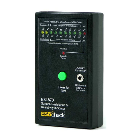
- Page 1 Surface Resistance/Resistivity Indicator ESI-870 Operations Manual...
- Page 2 Copyright 2001-2020 by ESD Check. All rights reserved. Printed in the United States of America. No part of this manual may be used or reproduced in any manner whatsoever without written permission. For information contact Prostat Corporation. ESD Check is the registered trademark of PROSTAT Corporation...
-
Page 3: Table Of Contents
ESI-870 Resistance/Resistivity Indicator TABLE OF CONTENTS ® ESD Check ESI-870 RESISTANCE/RESISTIVITY INDICATOR Title Page # Before using the Instrument ................... 3 Safety ..........................3 III. Description ........................3 Accuracy ......................... 4 Battery Installation & General Maintenance ..............5 Reading the ESI-870 Scale ..................... 7 VII. -
Page 4: Before Using The Instrument
ESI-870 Resistance/Resistivity Indicator Before using this, or any other electronic piece of equipment, carefully read the instruction manual completely. Before Using the Instrument Examine the instrument for damage, contamination (excessive dirt, grease, etc.) and defects. If any abnormal conditions exist, do not attempt to make any measurements. Safety The following safety information must be observed to insure maximum personal safety during the operation of this meter. -
Page 5: Accuracy
ESI-870 Resistance/Resistivity Indicator Controls & Electrodes The ESI-870 has one active control, a green "Press to Test" button on the front panel of the instrument. This button performs two functions: It turns the instrument ON, activating the test circuit and LED's. It applies test voltage to the electrode(s) and auxiliary connections. -
Page 6: Battery Installation & General Maintenance
ESI-870 Resistance/Resistivity Indicator For Surface Resistance/Resistivity measurements, the material under test should be placed on an "insulated" surface for best accuracy. The instrument must be fully positioned on the material being measured and the electrode switch must be switched “ON”. The instrument should be steadied by your fingers so that the full length of each electrode is making even contact with the material under test. - Page 7 ESI-870 Resistance/Resistivity Indicator Connect a fresh battery to the instrument battery power connector and insert the new battery into the case. Take care to position the battery connector wires to allow the battery cover to close easily. Replace the battery cover on the back of the meter by positioning it in the guide grooves and sliding it forward carefully.
-
Page 8: Reading The Esi-870 Scale
ESI-870 Resistance/Resistivity Indicator Place the instrument, with electrodes down, on a clean plastic insulating surface such as the white BOTTOM surface of the PTB-915 Test Bed. Measure the resistance of the plastic sheet using the "ESI-870 Operation Procedures" described below, i.e., Push the "Press to Test"... - Page 9 ESI-870 Resistance/Resistivity Indicator using the front panel Auxiliary Connection, and Resistance Point to Point (Rtt) when using the two Resistance Reference Auxiliary Connections located on the top end of the instrument. When the ESI-870 is used to measure Surface Resistivity of a Packaging Material in Ohms/Square per ASTM D-257, the bottom two brass electrodes are firmly placed against the material, and ESI-870 actuated.
- Page 10 ESI-870 Resistance/Resistivity Indicator The phono plug of the six foot lead is inserted in the front panel "Auxiliary Connection". The opposite end of the lead is connected to an ESD Ground reference, and the ESI-870 is then actuated. The resistance in Ohms between one electrode on the test material's surface and the ground point is displayed on the UPPER scale, above the LED's.
- Page 11 ESI-870 Resistance/Resistivity Indicator The resistance in Ohms between the two lead connection points is displayed on the UPPER scale, above the LED's. Note: The UPPER Scale unit of measure in this Rtt measurement mode is Ohms, not Ohms/square. The color indication and scale notes may, or may not describe the material's Static Control Classification, depending on the material or equipment being measured and the standard reference being used.
-
Page 12: Esi-870 Operation Procedures
ESI-870 Resistance/Resistivity Indicator The Red LED lights indicate the material is "Insulative", or greater than 1.0x10 Ohms, and possibly greater than the range of the ESI- 870. Note that when the instrument is used for Packaging Material Surface in Ohms as described above, the equivalent Surface Resistivity in accordance with ASTM D-257 in Ohms/Square is described on the UPPER Scale. - Page 13 ESI-870 Resistance/Resistivity Indicator Do not apply excessive pressure Positioning your fingers in this manner will allow you to steady the instrument and insure that the electrodes make full contact with the material. A measurement error of up to one order of magnitude may occur if full contact is not made between the brass electrodes and the material under test.
- Page 14 ESI-870 Resistance/Resistivity Indicator The Red LED located at right end of the scale should light briefly, then the Red center panel "Insulative -- Exceeds ESI-870 Range" LED should light. This indicates a very high resistance "Insulative" material measurement. This completes the "Initial Operational Check" If the highest decade LED "Insulative -- Exceeds ESI-870 Range"...
- Page 15 ESI-870 Resistance/Resistivity Indicator Read the LED indication in Ohms from the UPPER scale. Resistance Point to Point (Rtt) Measurement Procedure When the ESI-870 is used to measure Resistance between two points, i.e., Resistance Point to Point (Rtt) in Ohms, the two "Resistance Reference Inputs & Auxiliary Connections"...
-
Page 16: Functionally Testing The Esi-870
“ELECTRODES OFF” position. Insert the opposite ends of the leads into a Resistance ® Reference such as the PROSTAT PAR-809C Variable Resistance Reference The range of the resistance reference required is from >1.0x10... - Page 17 ESI-870 Resistance/Resistivity Indicator Gradually increase the resistance of the resistance reference while pressing the test button Record the resistance when the next LED lights and holds in a stable manner. This is the changeover resistance. Example: The first LED (10 ) is illuminated.
-
Page 18: General Specifications
ESI-870 Resistance/Resistivity Indicator ESI-870 Resistance/Resistivity Indicator Test Voltage & Current: Nominal 9 volts and 0.006 µA to 1.0 mA. Power: One (1) standard 9-volt battery, PROCELL, Eveready #216 (NEDA 1604, JIS 006P, IEC 6F22) Electrodes: 2 each Machined Brass, One (1) Square Resistivity configuration Overall Accuracy: + _ 10% Changeover Point:... - Page 19 ESI-870 Resistance/Resistivity Indicator...
- Page 20 Copyright 2001-2020, ESD Check Printed in U.S.A. www.esdcheck.com...
Need help?
Do you have a question about the ESD check ESI-870 and is the answer not in the manual?
Questions and answers