Advertisement
・ご使用前に必ず本書をお読みいただき、ご使用される方がいつでも見ることができる場所に必ず保管してください。
・本商品は、弊社の厳密なる品質および精度検査に合格した事を証明致します。
・Please read these instructions before use and keep them where the operator may refer to them whenever necessary.
・We certify this product has passed our rigorous inspections of quality and accuracy.
φ42
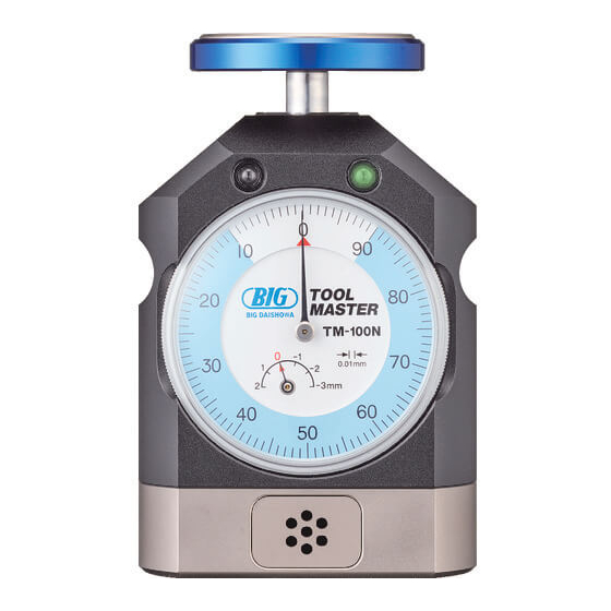
測定子
SENSOR
φ39
PLATE
L E D (緑)
LED (green)
L E D (赤)
LED (red)
ブザ−
BUZZER
φ63
マグネ ッ ト
MAGNET
●位置設定の前に
BEFORE SETTING
保護ク ッ シ ョ ン
測定子
PROTECTIVE
SENSOR
PLATE
CUSHION
基準面
REFERENCE
PLANE
●基準高さ設定
REFERENCE HEIGHT SETTING
付属のセッティングゲ−ジ
①
の両面の油分 ・ 埃等を取
り除いてください。
Remove oil and dirt on
both sides of the setting
gauge provided.
セ ッ ティ ングゲ−ジ
両面
Setting gauge
(clean both sides)
ツールマスター
取扱説明書
寸法及び主な仕様 DIMENSIONS AND MAJOR SPECIFICATIONS
バッ テ リ −
BATTERY
バッ テ リ −キ ャ ッ プ
BATTERY CAP
基準高さ位置設定 REFERENCE HIGHT POSITION SETTING
バッ テ リ ーキ ャ ッ プ
BATTERY CAP
電池 SR44×2
BATTERY 2×SR44
約2mm圧縮
Press down the
probe by about
2mm.
セ ッ ティ ング
ゲ−ジ
SETTING
GAUGE
TOOL MASTER
OPERATION MANUAL
項目
Items
高
さ
Height accuracy
ス
ト
Stroke
ス ト ロ − ク 範 囲
Stroke range
測
Measuring pressure
お 知 ら せ
信 号
Signaling
バ
ッ
Battery
質
Weight
最 小 測 定 工 具
Min. measurable tool diameter
54.8
付
Included items
ダイヤルゲ−ジ
精度
JIS B7503:1997
に準ずる
Dial gauge accuracy
in accordance with
JIS B 7503:1997
①測定子とス トッパー間の保護クッションを取り外してください。
Remove protective cushion between the probe and the stopper.
②電池のセッ ト方法
Setting of batteries
底面のバッテリ−キャ ップをコイン等で取り外し、 付属のバッテリ−(SR44)2個を左図
のように入れバッテリ−キャ ップを締め込んでください。 方向を逆に入れるとLED
が点灯しません。
Turn and remove the battery cap using a coin or similar and load the 2 batteries (SR44)
as illustrated left and then tighten the cap. If set reversely, the LED does not turn on.
③測定子の裏面と基準面の油分 ・ 埃等を取り除いてください。
Remove oil and dirt on bottom side of the sensor plate and top side of the reference plane.
ご注意 CAUTION
電池の方向を逆に入れるとブザーやLEDが反応しません。
Buzzer and LED do not react if the batteries are set in reverse direction.
測定子裏面と基準面の間にセッティン
②
グゲ−ジを装着後、 測定子の中心を指
でゆっくりと押し、 測定子裏面とセッテ
ィングゲージ表面を密着させてくださ
い。 密着させた状態で、 でダイヤルを
回し目盛板のゼロを長針に合わせます。
+0.02
密着時の高さが 1 0 0 mm です。
0
Place the setting gauge between the
sensor plate and the reference plane.
Slowly press down the center of the
probe until it contacts closely with
the setting gauge.
While holding the sensor plate,
adjust "0" of the dial to the long
hand. The height is 100
+0.02
mm when
0
the probe is in close contact with the
setting gauge.
OPERATION MANUAL DOWNLOAD SITE
http://big-daishowa.com/manual_index.php
型式
Model
TM-100N
精
度
1 0 0 mm
ロ
−
ク
9 2 〜10 2mm
定
圧
3 N (1 0 0mm時)
LED
点灯(緑) Lighting(green)
100.5mm 付近
ブザ−
ピ ッ
(Around 100.5mm)
BUZZER
LED
点滅(赤・緑)
99.5mm 付近
(Around 99.5mm)
ブザ−
ピッピッピッ
BUZZER
テ
リ
−
S R 4 4 × 2 P
量
セ ッ ティ ングゲ−ジ(Seetting gauge)× 1 P
属
品
S R 4 4 × 2 P
最
小
目
盛
0. 0 1mm
Graduations
指
示
誤
差
± 1 5 μm
Indication tolerance
繰 返 し 精 密 度
Repeatability
戻
り
誤
差
Return tolerance
③
セッティングゲ−ジをつけたまま使用すると工具の破損に繋
がります。 必ず取り外してご使用ください。 高さ1 0 0mm位
置は、 長針 0 短針 0 (約2mm圧縮時) の位置です。
Be sure to remove the setting gauge before use. Otherwise
tool will be damaged. The height is 100mm when the long
hand is on "0" and the short hand is on "0" (the probe is
pressed down by about 2mm).
ご注意 CAUTION
100mm位置は約2mm圧縮時な
ので、 高さ設定が終わった後、 指を
離して測定子が原点に戻った時、 必
ずしも長針は 0 には戻りません。
The height is 100 mm when the
probe is pressed down by about
2 mm. The long hand does not
always return, therefore, to "0"
when the probe has returned to
the initial point after the probe
was released.
■本 社
東 大 阪 市 西 石 切 町 3 丁 目 3 - 3 9 〒579-8013
TEL.072 ( 982) 2312 ( 代) FAX.072 ( 980) 2231
TM-100N
+0.02
0
1 0mm
Blipping
Flashing(red ・ green)
Blipping
1.0kg
φ 1mm
5 μm
5 μm
0
Advertisement
Table of Contents

Related Manuals for Big Daishowa TOOL MASTER


Summary of Contents for Big Daishowa TOOL MASTER
- Page 1 ツールマスター TOOL MASTER TM-100N 取扱説明書 OPERATION MANUAL ・ご使用前に必ず本書をお読みいただき、ご使用される方がいつでも見ることができる場所に必ず保管してください。 ・本商品は、弊社の厳密なる品質および精度検査に合格した事を証明致します。 OPERATION MANUAL DOWNLOAD SITE ・Please read these instructions before use and keep them where the operator may refer to them whenever necessary. http://big-daishowa.com/manual_index.php ・We certify this product has passed our rigorous inspections of quality and accuracy. 寸法及び主な仕様 DIMENSIONS AND MAJOR SPECIFICATIONS 型式 Model φ42 TM-100N 項目 Items 測定子 高 さ 精 度 SENSOR +0.02 1 0 0 mm φ39 0...
- Page 2 Green and red ・ When using Tool Master in cold climates or after a long idle period, move the probe several LED lights ash around strokes by nger in advance. Lubricant in precision slide and sealing on the inside may 99.5mm on the setting...
Need help?
Do you have a question about the TOOL MASTER and is the answer not in the manual?
Questions and answers