Riello BAG3 MIX BASIC Instructions For The Installaer And For Technical Assistance
Hide thumbs
Also See for BAG3 MIX BASIC:
Chapters
Table of Contents

Related Manuals for Riello BAG3 MIX BASIC


Summary of Contents for Riello BAG3 MIX BASIC
- Page 1 2 MIX BASIC MIX BASIC MIX BASIC ISTRUZIONI PER L’INSTALLATORE E PER IL SERVIZIO TECNICO DI ASSISTENZA EN INSTRUCTIONS FOR THE INSTALLER AND FOR TECHNICAL ASSISTANCE...
-
Page 2: Table Of Contents
ACCESSORI originali. Questo libretto di istruzione contiene importanti informazioni e Per gli accessori dedicati vedere il Listocatalogo Riello e la suggerimenti che devono essere osservati per una più semplice scheda prodotto. installazione ed il miglior uso possibile del BAG... -
Page 3: Generalità
GENERALITÀ GENERALITÀ 1.1 Avvertenze generali 1.2 Regole fondamentali di sicurezza Ricordiamo che l’utilizzo di prodotti che impiegano combustibili, Al ricevimento del prodotto assicurarsi dell’integrità e della energia elettrica ed acqua comporta l’osservanza di alcune re- completezza della fornitura ed in caso di non rispondenza a gole fondamentali di sicurezza quali: quanto ordinato, rivolgersi all’Agenzia r che ha venduto l’apparecchio. -
Page 4: Struttura
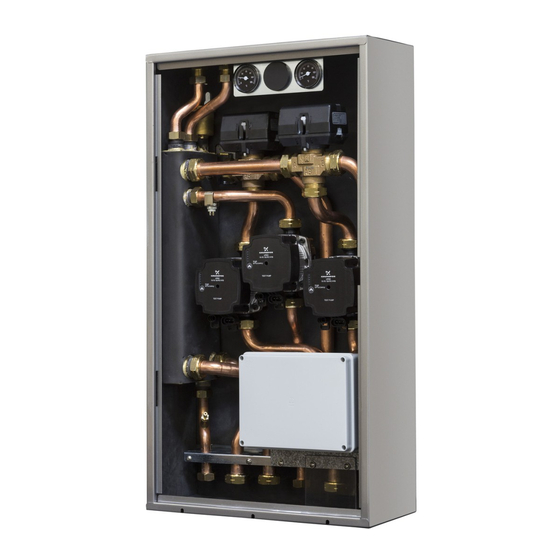
GENERALITÀ 1.4 Struttura MIX BASIC 2 MIX BASIC Rubinetto di scarico 10 Valvola miscelatrice impianto bassa Bottiglia di miscela temperatura 2 Circolatore impianto bassa temperatura 1 Circolatore impianto bassa temperatura 2 Circolatore impianto alta temperatura 12 Scatola connessioni elettriche Valvola di non ritorno (interna alla tubazione) 13 Termostato limite riarmo automatico Valvola miscelatrice impianto bassa impianto bassa temperatura 1... -
Page 5: Dati Tecnici
GENERALITÀ 1.6 Dati tecnici DESCRIZIONE MIX BASIC 2 MIX BASIC Alimentazione elettrica V~Hz 230(±10%)~50 Potenza massima assorbita Potenza assorbita dal singolo circolatore - min / max 6 / 52 Assorbimento elettrico del singolo circolatore - min / max 0,07 / 0,49 Campo di temperatura valvola miscelatrice °C 20 ÷... -
Page 6: Circolatori
GENERALITÀ 1.8 Circolatori è equipaggiato di circolatori ad alta efficienza e controllo elettronico le cui prestazioni, da utilizzare per il dimensionamento degli impianti, sono riportate nel grafico. Prevalenza utile del circolatore Potenza assorbita dal circolatore Portata (m Portata (m Prevalenza residua disponibile all’impianto Prevalenza residua disponibile all’impianto ALTA TEMPERATURA BASSA TEMPERATURA... -
Page 7: Schemi Elettrici
GENERALITÀ 1.9 Schemi elettrici 1.9.1 Schema elettrico BAG 2 MIX BASIC INGRESSO RICHIESTA CALORE CALDAIA o GENERATORE 5-24 4-14 4-14 5-24 4-14 5-24 marrone marrone marrone marrone marrone marrone nero 3/14 nero nero 4/11 nero 3-11 6-21 3-11 6-21 3-11 6-21 marrone marrone... -
Page 8: Schema Elettrico Bag
GENERALITÀ 1.9.2 Schema elettrico BAG MIX BASIC INGRESSO RICHIESTA CALORE CALDAIA o GENERATORE 4-14 5-24 4-14 5-24 marrone marrone marrone marrone nero 3/14 nero nero 4/11 nero 3-11 6-21 6-21 3-11 marrone marrone marrone marrone A2 blu marrone marrone marrone Fusibile 3.15A F TA3 grigio TA1 rosso... -
Page 9: Installazione
INSTALLAZIONE 2 INSTALLAZIONE 2.2 Dimensioni e pesi 2.1 Ricevimento del prodotto Il BAG (1) viene fornito in collo unico protetto da un imballo in cartone (2) all’interno del quale si trova una busta di plastica che contiene: − Rampe collegamenti idraulici (3) verso il generatore di ca- lore −... - Page 10 INSTALLAZIONE Per l’installazione del BAG all’interno del box, effettuare le se- − Fissare, utilizzando le apposite clip, i bulbi dei termo- guenti operazioni: metri con questa sequenza (partendo dal lato sinistro): − Inserire il lato destro del BAG all’interno del box e ruota- termometro (T1) alla rampa (C1) posta sotto il circolatore re il lato sinistro fino a far entrare completamente il BAG impianto BT1 e termometro (T2) alla rampa (C2) posta sotto...
-
Page 11: Zone Minime Di Rispetto
INSTALLAZIONE 2.4 Zone minime di rispetto 2.5 Schema di principio installazione tipica La figura mostra un esempio tipico di installazione del BAG NOTA: Per l’installazione di eventuali rubinetti (non forniti) oc- corre predisporre la nicchia di dimensione tale da poterli instal- lare sotto il BAG stesso. -
Page 12: Collegamenti Elettrici
INSTALLAZIONE 2.6 Collegamenti elettrici MIX BASIC Il BAG è predisposto con dei passacavi in gomma (1) posti nella parte superiore del box per il passaggio dei cablaggi elettrici. TA1 rosso TA3 grigio Cavo ingresso di rete 230V Di seguito verrà spiegato come collegare opportunamente il ai vari dispositivi e alla caldaia. -
Page 13: Messa In Servizio
MESSA IN SERVIZIO È vietato l’uso dei tubi del gas e dell’acqua per la messa a terra Indicazione dello stato di allarme dell’apparecchio. Se il circolatore ha rilevato uno o più allarmi il LED bicolore (B) è rosso. I quattro LED gialli (C) indicano la tipologia di allarme Il costruttore non è... - Page 14 MESSA IN SERVIZIO Prevalenza proporzionale visualizzazione Il circolatore lavora in funzione della domanda di calore dell’im- stato di pianto. Il punto di lavoro del circolatore e la curva di prevalenza > 2 s impostazione funzionamento proporzionale selezionata si sposteranno in funzione della do- manda di calore del sistema.
-
Page 15: Impostazione Impianto Bassa Temperatura
MANUTENZIONE 3.3 Impostazione impianto bassa temperatura 4.2 Svuotamento del BAG Fissare la temperatura di mandata dell’impianto bassa tempe- Prima di iniziare le operazioni di svuotamento posizionare l’in- ratura regolando manualmente la valvola miscelatrice riferen- terruttore generale su “spento”. dosi alla tabella seguente. Per svuotare il BAG −... - Page 16 ACCESSORIES quired. This instruction manual contains important information and Please refer to the Riello price list and the product information suggestions which must be observed in order for installation sheet for the specific accessories. to be as simple as possible and for the best possible use to be...
-
Page 17: General
GENERAL GENERAL 1.1 General instructions 1.2 Basic safety rules Remember that the use of products which use fuel, electricity On receiving the product, ensure that it is complete and in- and water requires the observance of some basic safety rules tegral and if it does not comply with the order made, con- such as: tact the r Agency who sold the appliance. -
Page 18: Structure
GENERAL 1.4 Structure MIX BASIC 2 MIX BASIC Drain cock 10 Mixing valve low temperature system 2 Mixing bottle Circulation unit low temperature system 2 Circulation unit low temperature system 1 12 Electrical connection box Circulation unit high temperature system 13 Automatic rearming limit thermostat Non-return valve (inside the pipe) low temperature system 1... -
Page 19: Technical Data
GENERAL 1.6 Technical data DESCRIPTION MIX BASIC 2 MIX BASIC Electrical power supply V~Hz 230(±10%)~50 Maximum absorbed power Power absorbed by each individual circulation unit - min/max 6 / 52 Electrical power of each individual circulation unit - min/max 0.07 / 0.49 Mixing valve temperature range °C 20 - 60... -
Page 20: Circulation Units
GENERAL 1.8 Circulation units is equipped with high efficiency electronically controlled circulation units. The performance data of these units to be used to size the system is shown in the graph. Available head of the circulation unit Power absorbed by the circulation unit Flow rate (m3/h) Flow rate (m3/h) Residual head available to the system... -
Page 21: Wiring Diagram
GENERAL 1.9 Wiring diagram 1.9.1 BAG 2 MIX BASIC wiring diagram INGRESSO RICHIESTA CALORE CALDAIA o GENERATORE 5-24 4-14 4-14 5-24 4-14 5-24 marrone marrone marrone marrone marrone marrone nero 3/14 nero nero 4/11 nero 6-21 3-11 3-11 6-21 3-11 6-21 marrone marrone... -
Page 22: Bag Mix Clima Wiring Diagram
GENERAL 1.9.2 BAG MIX CLIMA wiring diagram GI/VE GI/VE Fusibile 3.15A F GI/VE If the wiring or the board are replaced, observe and respect all the connections of the cables according to the numbered sequence shown in the figure. -
Page 23: Installation
INSTALLATION 2 INSTALLATION 2.2 Dimensions and weights 2.1 Receiving the product The BAG (1) is supplied in one package, protected by cardboard packaging (2) inside of which there is a plastic envelope con- taining: − Plumbing connection ramps (3) towards the heat gen- erator −... - Page 24 INSTALLATION To install BAG inside the box, proceed as follows: − Using the designated clips, secure the thermometer bulbs − Insert the right side of the BAG inside the box and ro- following the sequence (from left to right): thermometer tate the left side until the BAG enters completely making (T1) to the ramp (C1) located below the BT1 system circula-...
-
Page 25: Minimum Distances
INSTALLATION 2.4 Minimum distances 2.5 Typical installation layout The figure shows an example of a typical installation of the BAG N.B.: For the installation of any cocks, (not supplied), a niche must be formed of a sufficient size to allow them to be fitted below the BAG itself. -
Page 26: Electrical Connections
INSTALLATION 2.6 Electrical connections MIX BASIC The BAG is prearranged with rubber cable feed-throughs (1) located in the top section of the box allowing wiring to be passed through. TA1 rosso TA3 grigio Cavo ingresso di rete 230V Below is an explanation of how to correctly connect the BAG the boiler and on devices. -
Page 27: Commissioning
COMMISSIONING er’s electrical power rating. Please refer to the technical Consumption CIRCULATION UNIT data to check LED status in % of status − the electrical power rating for the model installed P1 MAX (*) − to connect the appliance to an efficient earthing system Green LED on + Operation at minimum 0-25... - Page 28 COMMISSIONING Changing the operating mode Proportional head In normal operating conditions, the circulation unit operates The circulation unit works on the basis of the heat request made with the factory settings or the last settings made. by the system. The working point of the circulation unit and the selected proportional head curve move on the basis of the heat To change the configuration: request...
-
Page 29: Setting The Low Temperature System
MAINTENANCE 3.3 Setting the low temperature system 4.2 Draining the BAG Set the low temperature system delivery temperature by man- Before starting draining operations, set the main switch to "off". ually adjusting the mixing valve and referring to the following table. - Page 32 RIELLO S.p.A. 37045 Legnago (VR) Tel. 0442630111 - Fax 044222378 - www.riello.it RIELLO S.p.A. 37045 Legnago (VR) Poiché l’Azienda è costantemente impegnata nel continuo perfezionamento di tutta la sua produzione, le caratteristiche estetiche e di- Tel. 0442630111 - Fax 044222378 - www.riello.it mensionali, i dati tecnici, gli equipaggiamenti e gli accessori, possono essere soggetti a variazione.
Need help?
Do you have a question about the BAG3 MIX BASIC and is the answer not in the manual?
Questions and answers