Table of Contents
Advertisement
Advertisement
Table of Contents

Related Manuals for Husqvarna DM 650


Summary of Contents for Husqvarna DM 650
- Page 1 Workshop manual DM 650 HUSQVARNA CONSTRUCTION PRODUCTS...
-
Page 2: Table Of Contents
CONTENTS Page HUSQVARNA DOCUMENTATION 2. COMPONENTS, WORK TIPS DM 650 DISMANTLING IN BASIC MODULES 4. GEAR HOUSING – PRIMARY SHAFT 5. GEAR HOUSING – SLIP CLUTCH 6. GEAR HOUSING – SECONDARY SHAFT 7. GEAR HOUSING – SPINDLE SHAFT 8. GEAR HOUSING – BEARING REPLACEMENT 9. - Page 3 Spare parts DM 650 GEAR BOX The folder includes all spare parts for Husqvarna DM650. The folder contains complete exploded drawings for the whole machine where the location, spare parts number and appearance of each component is easy to identify.
-
Page 4: Components, Work Tips
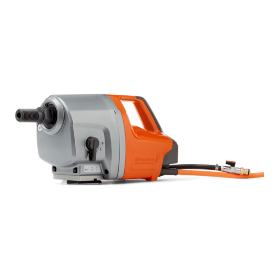
COMPONENTS, WORK TIPS 7. Water hose 14. Speed display (digital indication 1–6) Components 1. Drill spindle 8. Electric cable 15. Speed control 2. Gear housing 9. ID plate 16. Full/half speed breaker 3. Gear box cover 10. Stand mount 17. Circuit breaker 4. - Page 5 DISMANTLING BASIC MODULES Dividing basic modules For repair work only involving the gear housing, such as changing the spindle shaft, the machine is divided as shown in the top image and as described below. The division is made between the gear housing and the gear box cover on the gear housing.
- Page 6 DISMANTLING BASIC MODULES Division – gear housing/motor housing 1. The panel is secured with five screws. Remove these. Lift off the panel. 5 x MT 5x14, 3–4 Nm 2. Remove the three screws to the circuit board. 3 x MT 5x20, 2–4 Nm 3.
-
Page 7: Gear Housing - Primary Shaft
GEAR HOUSING – PRIMARY SHAFT Gear housing The gear housing contains a transmission that reduces the high speed of the electric motor to a lower speed on the spindle shaft. The transmission is based on three shafts: A. The primary shaft where the upper gear wheel is driven by the gear wheel on the motor's output shaft. -
Page 8: Gear Housing - Slip Clutch
GEAR HOUSING – SLIP CLUTCH Function The electric motor powers the top gear wheel on the primary shaft. This gear wheel has a slip clutch to protect the operator and the gear box in the event of jamming. The cup springs provide the clamping force for the slip torque. Place flat friction washers on both sides of the gear wheel. - Page 9 GEAR HOUSING – SLIP CLUTCH Tools – adjusting the slip torque Special tools produced by Husqvarna are needed to adjust the slip torque. A torque gauge with continuous reading is also needed. 581 92 82-01 581 92 82-01 Turning pliers with 17 mm jaw width.
- Page 10 GEAR HOUSING – SECONDARY SHAFT Dismantling Starting position Lift off the spacer ring and brass washer at the top of the secondary shaft if this has not already been done. Remove the spindle shaft gear wheel, see Page 12. Remove the complete primary shaft, see Page 7. Remove the gear knob 1.
-
Page 11: Gear Housing - Secondary Shaft
GEAR HOUSING – SECONDARY SHAFT Remove the secondary shaft Remove the secondary shaft using a standard puller. Place two wooden strips on the gear housing and place a heavy metal object such as a chisel as a bridge between the wooden strips. Fasten the puller claw under the gear wheel. -
Page 12: Gear Housing - Spindle Shaft
GEAR HOUSING – SPINDLE SHAFT Remove the spindle shaft Start by lifting off the slip clutch on the primary shaft. Remove the retaining ring on the spindle shaft: Expand the retaining ring using special pliers and lift up the Pliers: ring gradually all around with a screwdriver. - Page 13 GEAR HOUSING – SPINDLE SHAFT Bearing replacement Remove the bearing Remove the bearing's inner circlip. Remove the bearing from the shaft using the bearing puller 531 00 48-67 or with a hydraulic press. Replace the radial seal Always replace the radial shaft seal if the spindle shaft is removed or replaced.
-
Page 14: Gear Housing - Bearing Replacement
GEAR HOUSING – BEARING REPLACEMENT Tools Dismantling The following tools are required for removing the gear housing's bearing: 1. Internal bearing extractor to grip behind the bearings. 2. Use a counter stay device where there is a counterhold. 3. A slide hammer is an alternative to the counter stay device if there is no counterhold available. - Page 15 GEAR HOUSING – BEARING REPLACEMENT The spindle shaft bearing in the gear box cover Dismantling The bearing is easily removed with a counter stay device as shown in the adjacent image. Place a few pieces of wood under the legs of the counter stay device to distri- bute the pressure.
-
Page 16: Motor
The rotor has permanent magnets and therefore has no carbon brushes. A typical feature is the high power to weight ratio. The motor has been designed by Husqvarna. A unique feature is the advanced cooling system. This and the motor function are described on the next page. - Page 17 MOTOR Function Working method The way in which the high frequency motor works differs significantly from a traditional motor with rotor windings and collector/carbon brushes. The rotor in the high frequency motor consists of permanent magnets with a high magnetic force, known as neodymium mag- nets.
-
Page 18: Electrical Components
ELECTRICAL COMPONENTS Wiring diagram Electrical connection for HF unit Connection for HF unit Circuit board Connections to motor and circuit board Switch Motor Motor Circuit board with display and switch... - Page 19 Hose clips Oetiker system The machine is originally fitted mainly with a single-use Oetiker ear clip. This type of clip has the advantage of being able to give small- dimension hoses even clamping force all round with a minimal risk of leakage.
- Page 20 Water valve The water valve has a connection for the Gardena coup- ling. To cool the motor, the machine must always be run with water. The only exception is short test running in the workshop without any load. Filter The hose coupling on the inlet side is fitted with a filter that should be checked when servicing and cleaned, or replaced if it is damaged.
- Page 21 A multimeter is needed for most of the tests in order to measure resistance (ohm) and inductance (H = Henry). The multimeter's connection test with a buzzer is used to check switches, cables, contacts, etc. (The Husqvarna range of tools includes an efficient multimeter; see page 25.) Insulation and continuity tester The motor works with a voltage of just over 500 V AC.
-
Page 22: Troubleshooting
TROUBLESHOOTING Motor Disassemble the machine to ensure that the motor connectors are accessible, as shown in the previous image. In order to test the motor magnets, the motor must be removed from the machine. Short-circuit testing Check first to make sure that the motor does not have shorted windings to earth (motor material). - Page 23 TROUBLESHOOTING Thermistor The thermistor is the motor's temperature monitor. It breaks the current to the motor if the temperature is too high. A defective thermistor may prevent the motor from starting. The thermistor is connected to the display unit on the cutting machine, which issues a warning if the motor temperature is too high.
- Page 24 TROUBLESHOOTING Signal cables, connection testing and insulation testing This test is used to check whether any cable is broken and whether there is any damaged insulation which is causing the wires to come into contact with one another. This test is carried out with a multimeter set for connection testing with a buzzer signal.
-
Page 25: Tools
TOOLS ● = Service stage The tools below can be acquired from Husqvarna. 531 12 31-22 581 54 15-01 Clamping ring Multimeter Make: Amprobe 37XR-A. Adjustment of the gear box's ● One of few universal instru- slip clutch. ments that can also measure Used together with adapter 522 91 inductance (H, Henry). - Page 26 www.husqvarnacp.com 115 66 63-26 English 2013-11...
Need help?
Do you have a question about the DM 650 and is the answer not in the manual?
Questions and answers