Table of Contents
Advertisement
Quick Links
Advertisement
Table of Contents

Related Manuals for ECD Brake Board


Summary of Contents for ECD Brake Board
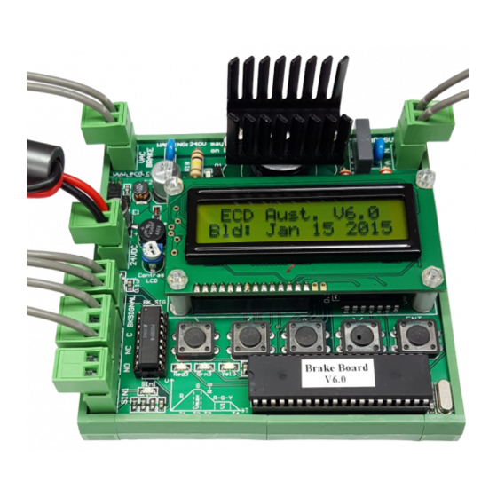
- Page 1 Brake Board Manual Revision Date: Jan 19, 2018 ECD System Manual...
- Page 2 E L E C T R O N I C C I R C U I T D E S I G N S P T Y . L T D . Operation Guide This manual covers all versions of Brake Board hardware and software, although some features...
-
Page 3: Table Of Contents
1.2.4 Safety during normal operation................... 5 1.2.5 Hazards caused by electric power................5 2.1 Product Overview ....................6 2.2 Contents of the Brake Board Kit................6 2.3 Connection of ECD Brake Board ................6 2.3.1 24VDC ..........................6 2.3.2 BKSIGNAL ........................ -
Page 4: Section 1.1 Safety Regulations
Section 1.1 Safety Regulations Installation of this equipment shall be done in accordance with all applicable local codes Elevator controllers and other electrical components can cause serious harm or death if installation guides are not met. It is the responsibility of the installer of our equipment to ensure that once installed, the equipment does not pose any threat, danger or hazard. -
Page 5: Safety During Normal Operation
1.2.4 Safety during normal operation. Only operate the machine when all protective equipment is fully operational. Prior to switching on the machine, ensure that the startup can cause no harm to personnel. Regularly maintain and check machine for externally identifiable damage and check that all the safety devices are operational. -
Page 6: Product Overview
2.1 Product Overview The brake board is specifically designed to control elevator machine brakes across a wide range of voltages and loads. It may also be used to control door lock cams to ensure smooth and quiet cam operation. The following user adjustable parameters ensures smooth and quiet brake operation and reduction of back EMF surges;... -
Page 7: Bksignal
The NO NC C relay contacts are used to signal to the lift controller that a fault has occurred with the brake board, inhibiting any further lift operation. See example Section 4, Fig. 6 & 7, where the relay C & NO contacts are used for the controller PRV (prove) input. -
Page 8: Sin 1
This fault is a fatal error and requires a 24VDC reset. Note: If a triac fault is detected while the brake board is operating, the brake board will finish the run and set the Triac damaged fault when BK SIGNAL turns off. -
Page 9: Brake Coil And Rectifier Connections
2.3.7 Brake Coil and Rectifier Connections The wiring current rating from the VAC BRAKE output to the rectifier and brake should be sized according to the load of the brake coil. The supplied power diode shall to be connected reverse biased at the brake coil for back EMF suppression. -
Page 10: Setup Of Brake Board
E.g.2. Set to 100% if AC SUPPLY is 240VAC and you require 240VAC at VAC BRAKE. The Brake Board is shipped with Vmax set at a default value of 35%. The minimum allowed setting is 10% and the maximum setting is 100%. - Page 11 2.4.3 T1 This setting is used to control how fast the brake coil will get to full voltage (v max). It is adjustable in steps of 50 ms. The minimum allowed setting is 100ms and the maximum allowed setting is 5000 ms. Default setting is 500ms.
-
Page 12: Led Sequence Of Operation
2.5 LED Sequence of Operation Fitted to the Brake Board are 3 LED’s which can be used to follow the sequence of operation of the board. The LED’s are red, green and yellow. During standby state both the red and yellow LED’s are illuminated. -
Page 13: Specifications
3. Specifications 3.1. AC SUPPLY input voltage range 80VAC – 240VAC @50Hz For AC SUPPLY input voltage less than 80VAC contact ECD for resistor upgrade. 3.2.1 VAC BRAKE output current capable ratings. Output current ratings reduce as V Max reduces. -
Page 14: Example Connection
4. Connection Example: The diagrams below show an example of how the Brake Board may be connected Figure 7... - Page 15 Figure 8...
- Page 16 E L E C T R O N I C C I R C U I T D E S I G N S P T Y . L T D . Operation Guide Electronic Circuit Designs Pty. Ltd. Factory 11/30 Perry Street • Matraville • NSW • Australia • 2036 Phone 61 2 9316 6909 • Fax 61 2 9316 6797 Email sales@ecd.com.au www.ecd.com.au...
Need help?
Do you have a question about the Brake Board and is the answer not in the manual?
Questions and answers