Table of Contents
Advertisement
Advertisement
Table of Contents

Related Manuals for ECD OvenRIDER NL2+


Summary of Contents for ECD OvenRIDER NL2+
- Page 1 Quick RefeRence Guide...
-
Page 2: Table Of Contents
cOnTenTS WELCOME .......................... 2 EQUIPMENT ........................3 FEATURES/FUNCTIONS....................3 SETUP ..........................4 CHARGING THE POWER PACK ..................4 SOFTWARE INSTALLATION .................... 6 SOFTWARE REGISTRATION ................... 8 COMMUNICATIONSv9 ZONE BOUNDARY MAGNET INSTALLATION ..............11 OPERATION ........................13 INTRODUCTION ......................13 STEP 1: SETUP INSTRUMENT ..................14 STEP 2: DATA COLLECTION .................. -
Page 3: Welcome
This Quick Reference Guide is designed to help the user to familiarize themselves with the equip- ment, perform basic hardware setup/communications and operation. For detailed information on both Hardware & Software components, please refer to the Help system accessible in the M.O.L.E.®... -
Page 4: Equipment
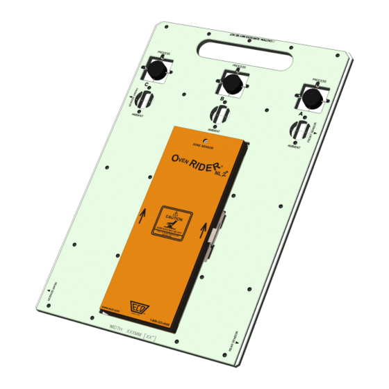
eQuiPMenT feATuReS/funcTiOnS Process and Ambient Sensors: Zone Sensor Battery A combination of 3 thermal and This is the power source for the 3 position sensors that measure zone sensor light. oven performance. Zone Sensor Light: This light illuminates when the detects zone boundary magnets. -
Page 5: Setup
1. Insert the USB cable male series “A“ plug into a computer USB Port. 2. Insert the USB cable male series “B” mini plug into the Data/Charging Port. A completely discharged Power Pack takes about 8 hours to be fully ①... - Page 6 SeTuP cHARGinG THe POWeR PAck 1. Remove the Power Pack. 2. Plug the transformer end of the charger- into a (120 or 230VAC) wall outlet and ① the connector end into the Power Pack. A completely discharged Power Pack takes about 14 hours to be fully charged.
-
Page 7: Software Installation
1. Insert the Flash Drive in a USB Port and the AutoPlay menu appears. 2. Select Open folder to view files but- ton on the AutoPlay menu to launch Windows® Explorer. Closely follow the instructions for your operating system. For detailed information view the Instal- lation Help file on the Flash Drive. - Page 8 SeTuP SOfTWARe inSTALLATiOn The user must have administrator permissions for the computer to in- stall and register the software. To install as administrator, locate the setup.exe on the installation drive. Right-click the file to display the shortcut menu and select Run as ad- ministrator.
-
Page 9: Software Registration
An Unlock Key can be obtained via an online registration form or using the contact infor- mation supplied on the dialog box, contact ② ECD. 1. On the Help menu, click Register and the dialog box appears. 2. Select Online Registration and enter the required information on the M.O.L.E.®... - Page 10 SeTuP cOMMunicATiOnS 1. Plug the computer interface cable into a computer COM Port and the other end into the M.O.L.E.® Profiler Data Port. When using a SuperM.O.L.E. Gold 2, the AutoPlay panel appears in the USB/RS-232 lower right corner of the desktop. Adaptor This panel displays the four most common MAP commands.
- Page 11 3. Select the desired instrument from the dialog box. If there are none displayed, ③ click the Scan for Instruments command button to detect all available instru- ments. 4. Click the OK command button to accept. Once a M.O.L.E.® Profiler has been se- ④...
-
Page 12: Zone Boundary Magnet Installation
SeTuP ZOne MAGneT inSTALLATiOn 1. The zone boundary magnet kit is supplied with two dif- ferent types of magnet clips designed to mount the mag- nets to the reflow oven rail. Reflow ovens may have differ- ent conveyor rails than the one used in these instructions, so determine which type will best mount the magnets in your oven. - Page 13 • When the RIDER front and rear zone sensors pass the magnet, the Zone sensor light stay illuminat- ed while each sensor has moved past it for .75” +/- .25” (1.9cm +/- .6cm). • When the RIDER passes the magnet, the Zone sensor light must not double flash.
-
Page 14: Operation
OPeRATiOn inTROducTiOn This operation procedure guides you through a typical process on how to set a M.O.L.E.® Ther- mal Profiler up for performing a OvenRIDER® NL 2+ data run. For additional detail, consult the Help System in the software. The M.O.L.E.® Thermal Profiler depends on the MAP (Machine-Assembly-Process) software to control how it collects and interprets data. -
Page 15: Step 1: Setup Instrument
STeP 1: SeTuP inSTRuMenT Open the M.O.L.E.® MAP software. Connect the M.O.L.E.® Thermal Profiler to the computer. ④ Make sure the M.O.L.E.® Power Pack battery is fully charged. When a M.O.L.E.® Thermal Profiler is se- lected, the software status bar displays the current battery voltage. - Page 16 OPeRATiOn SeTuP inSTRuMenT When navigating through the wizard, ⑥ the step list on the left of the dialog box uses a color key to inform the user of the progression through the wizard. Current Completed Remaining On the M.O.L.E.® menu, select Setup Instrument and the workflow wizard appears.
- Page 17 For settings such as Start Parame- ters and Stop Parameters, select the More>> command button. Select the Sensor Platform button. ⑦ Select the OvenRIDER® NL 2+ then the OK com- mand button to proceed. Confirm the settings and then, select the Next command button to send the data listed in the dialog box to the instrument.
- Page 18 OPeRATiOn SeTuP inSTRuMenT Confirm the assembly information. ⑩ Click the Next command button. ⑪...
- Page 19 Verify the instrument status. This dialog box ⑫ displays the health of the M.O.L.E.® Profiler such as battery charge, internal temperature, thermocou- ple temperatures. If everything is OK, the dialog box dis- plays a GREEN sign. If there are any items that may prevent the user from collecting good data, they are high- lighted and a...
-
Page 20: Step 2: Data Collection
OPeRATiOn dATA cOLLecTiOn STeP 2: dATA cOLLecTiOn Never permit the M.O.L.E.® Thermal Pro- ③ filer to exceed the absolute maximum warranteed internal temperature, as per- ③ manent damage may result. The warranty will not cover damage caused by exceed- ing the maximum specified internal tem- perature. - Page 21 Close the Thermal Barrier cover and latch ⑤ securely. ⑥ Place the RIDER on the reflow oven conveyor. Make sure the RIDER is fed into the machine in the proper direction. There are two arrows on the RIDER barrier that indicates the prop- er direction.
- Page 22 OPeRATiOn dATA cOLLecTiOn It is important to open the Thermal Barrier to prevent the internal temperature of the M.O.L.E.® Profiler to rise above operating tem- perature specification. ⑧ ⑧ Open the Thermal Barrier and if the Record button is still flashing this means the M.O.L.E.® Profiler is still logging and it should be stopped.
-
Page 23: Step 3: Download Data
STeP 3: dOWnLOAd dATA Connect the M.O.L.E.® Thermal Profiler to a the AutoPlay panel appears computer and in the lower right corner of the desktop. Select the Read Instrument command and the workflow wizard appears. ② OPeRATiOn dOWnLOAd dATA... - Page 24 OPeRATiOn dOWnLOAd dATA Select the desired data run from the M.O.L.E.® memory list and then click the Finish com- mand button to complete the wizard and read the data run from the M.O.L.E.® Profiler. ③ If a data run (*.XMG) is saved in a dif- ferent Environment Folder other than the currently selected, the software automatically activates the new Envi-...
- Page 25 When the data run has been downloaded, the software will prompt the user to name and save the data run file (*.XMG). To prevent data loss, it is recom- mended that data run files (*.XMG) are not saved in the M.O.L.E. MAP Sample Environments.
Need help?
Do you have a question about the OvenRIDER NL2+ and is the answer not in the manual?
Questions and answers