Table of Contents

Subscribe to Our Youtube Channel
Summary of Contents for Dometic SeaWays
- Page 1 POWER & CONTROL SEAWAYS SEAWAYS AND SEAWAYS GO Integrated Autopilot System Installation and User’s Manual — Book 67 WARNING Cancer and Reproductive Harm [REVISION C] Form No. 682208 | ©2020 Dometic Corporation www.P65Warnings.ca.gov...
- Page 2 ©2020 Dometic All Rights Reserved. This document, subject matter and all information herein is the sole, exclusive and confidential property of Dometic and shall not be disclosed, copied, reproduced or used in whole or in part for any purpose other than as specifically authorized in writing by Dometic.
-
Page 3: Table Of Contents
3 User ..................3-1 3.1 Overview ..............3-1 3.2 SeaWays operation ............3-1 3.2.1 SeaWays modes ............. 3-1 3.2.2 How to engage and disengage SeaWays ....3-3 3.2.3 Override mode ............ 3-4 3.2.4 Heading bump ............. 3-4 3.2.5 Route Mode Considerations ........3-5 3.3 3rd party autopilots ............ -
Page 4: Abbreviations
3.5.2 Qualified marine mechanic ........3-7 3.5.3 Replacement parts ..........3-7 3.6 Mounting templates ............3-9 3.6.1 SeaWays low profile mount ........3-9 3.6.2 SeaWays high profile mount ........3-11 3.6.3 SeaWays GO direct mount ........3-13 3.6.3 SeaWays GO bracket mount ......... 3-13 4 Warranty ................ -
Page 5: Important Safety Information
1 Important Safety Information Safe operation of the SeaWays and SeaWays GO integrated autopilot depends on proper installation and maintenance of the system, as well as the operator’s safe judgment, boating knowledge, and expertise. The installer and operator must read and understand the safety requirements in this section before installing or using the steering system. -
Page 6: Safe Operation
• Know and obey all applicable federal, state, and municipal laws and regulations that govern boating in your area. Dometic recommends all boat operators take a boating safety course. • Never operate a boat while under the influence of drugs or alcohol. -
Page 7: Safety Considerations For Installers
– refer also to those instructions. • Do not substitute any component of the system. Dometic parts are rigorously engineered and tested to ensure system integrity. Substitution of components may compromise safety, performance, and reliability. - Page 8 This page left intentionally blank.
-
Page 9: Installation
The system uses position and heading data to steer the vessel automatically. The SeaWays GPS sensor allows Heading, Track, and Route modes whereas the SeaWays GO compass allows Heading mode. For more information on the three modes of operation, please refer to section 3. -
Page 10: Installing The Seaways Gps Sensor
2.3 Installing the SeaWays GPS sensor Mounting location 2.3.1 This section provides information on determining the best location for the sensor. NOTICE! The sensor should be mounted as low as possible while still maintaining good sky visibility. This will reduce false movement due to the boat rocking back and forth. -
Page 11: Mounting Alignment
Figure 2-1. Sensor mounting distance from nearby VHF antennas and other equipment. Mounting alignment 2.3.2 The SeaWays sensor should be mounted parallel to, and along the centerline of, the axis of the boat. The bottom of the sensor has an arrow – the arrow must point forward. -
Page 12: Mounting Options
This section provides information on determining the best location for the SeaWays sensor. The SeaWays kit that is purchased determines the mounting style; either surface mount or pole mount. The sensor allows for both pole or surface mounting. Follow directions below for detailed mounting directions. -
Page 13: Surface Mount Dimensions
Surface mount dimensions 2.4.3 6.23" 13.71" 3.00" 4.39" 5.60" 2.90" 2.90" 4X Ø 0.25" Figure 2-3. Sensor with low profile mount accessory dimensions. 6.23" 13.71" 4.22" 3.54" 4.77" 2.50" 4X Ø 0.35" 3.70" Figure 2-4. Sensor with high profile mount accessory dimensions. -
Page 14: Pole Mount Dimensions
Pole mount dimensions 2.4.4 6.23" 13.71" 6.61" 1.0"–14 1.00" Figure 2-5 : Sensor with pole mount accessory dimensions. Cable considerations 2.4.5 Before mounting the sensor, consider the following regarding cable routing: • Avoid running the cable in areas of excessive heat •... -
Page 15: Surface Mount
Surface mount 2.4.6 Two options exist for surface mounting the SeaWays antenna, low profile and high profile mount (figure 2-6). A flat surface is required and the flat surface may be something you fabricate per your installation, an off-the-shelf item (such as a radar mounting plate), or an existing surface on your vessel. - Page 16 3. Secure the mount to the installation surface. Tighten to a maximum torque of 10 lbs-ft. 4. Secure the surface mount adapter to the SeaWays sensor using the supplied hardware. Tighten to a torque of 8–10 lbs-ft with no more than 0.5 in thread depth engagement.
-
Page 17: Pole Mount
4. Thread the communication cable through the hollow pole or through the opening in the pole mount and connect to the SeaWays sensor. 5. Secure the pole mount to the SeaWays sensor using the supplied mounting hardware. Tighten to a torque of 8–10 lbs-ft. The maximum thread depth must be no more than .5 in. -
Page 18: Installing The Seaways Go Sensor
Optimus EPS systems. The sensor must be purchased from Dometic in order to be licensed as such. The SeaWays GO compass sensor can be mounted on a flat surface or bulkhead, athwart ship or along ship. Select a location that provides a solid mounting place free from vibration (as much as possible), and as close to the vessel’s centre of roll and pitch as possible, i.e. - Page 19 1. When the compass is in fitted in place, the mounting screws should only be tightened loosely (half way) at first. 2. Mechanically adjust compass orientation to be parallel to boat’s center line as shown in figure 2-12 and figure 2-13. Figure 2-12.
-
Page 20: Calibrating The Seaways Go Sensor
Use the supplied mounting kit, including the mounting template, and drill holes. NOTICE! Never mount the compass upside down! Level the sensor as close to horizontal as possible. Sensor Dimensions Figure 2-14 illustrates the physical dimensions of the SeaWays GO sensor. 3.54" Ø1/4" MOUNTING HOLE 2 PLACES 4.69"... -
Page 21: Electrical Connection
GPS or compasses. For the SeaWays sensor: The installation kit for SeaWays comes with a 20 foot network cable, a 1 foot network cable and a tee connector. If the 6-way hub in the Optimus 360 installation is full, remove the terminator and connect the 1 foot network cable in its place. - Page 22 Figure 2-15. 2. Enter the license code (captured on back cover of this booklet). 3. Make sure the new license code is correct and press OK to confirm. Figure 2-16. 4. Check that the Sensor Status has changed to Licensed. If it has not, retry entering the license code.
-
Page 23: Commissioning
Engine speed at • Idle • Planing • WOT AP sensitivity • Low Speed • High Speed NOTE SeaWays and SeaWays GO has to be enabled and commissioned before use. NOTE Some of the Autopilot parameters do not need to be tuned for the SeaWays GO system. - Page 24 If SeaWays is not used it can be disabled. Default is disabled. Figure 2-19. 2. For the SeaWays GO compass, the Compass Offset menu will not be available. The heading sensor output can be deviating slightly from the boat’s center line and not impact the performance of the system.
- Page 25 3. Define idle, planning and maximum engine RPM’s. Figure 2-21. 4. Drive boat at 5–6 knots, engage heading mode, jog target heading by 10°. Reduce sensitivity if boat turns too aggressively or overshoots. Increase sensitivity if autopilot is too lazy. Figure 2-22.
-
Page 26: Settings
Settings 2.8.2 General user settings can be accessed using the CANtrak display. To access these settings press the MENU button and then SETTINGS. Figure 2-24. User level sensitivity adjustments can be made from this menu as well as waypoint alarm options. Figure 2-25. - Page 27 1. Global sensitivity adjustment. Figure 2-26. Commissioning Sub Parameter Settable Default Procedure/Description Parameter Range Value Sensitivity Low Speed -40 to 40% 0% Autopilot gain adjustment at low speed: Decrease if Adjustment boat turns too aggressively when jogging heading Increase if response is too lazy Low Speed Counter -40 to 40% 0% Autopilot reaction adjustment at low speed: Decrease if heading is unstable at low speed...
- Page 28 10 to 300 m Yes If cross-track error is greater than this parameter, then Warn fault 0x7F1A1 is triggered (Significant cross-track error detected) Table 2-3. NOTE Only Heading Error to Warn parameter is applicable for the SeaWays GO system. 2-20...
-
Page 29: Sea Trial
3. An option also exist to reset SeaWays user options to default. Figure 2-29. Commissioning Sub Parameter Settable Default Procedure/Description Parameter Range Value Options Enable Override Yes/No When set to “No”, turning the helm in heading or Mode track modes causes the autopilot to disengage. -
Page 30: Troubleshooting Guide
2.9 Troubleshooting guide Optimus SeaWays will provide years of safe reliable performance with a minimum of service if properly commissioned. Most faults occur when the installation instructions are not followed and usually show up immediately. Listed below are the most common faults encountered and their likely cause and solution. -
Page 31: User
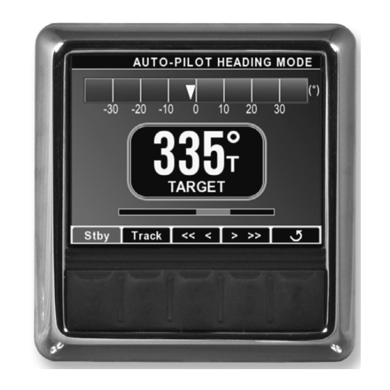
3 User 3.1 Before each use SeaWays and SeaWays GO are feature rich autopilots that is integrated into Optimus 360 systems. An autopilot is a useful navigational aid, but DOES NOT under any circumstances replace a human navigator. When using an autopilot: •... - Page 32 NOTE Track and route mode are not available using SeaWays GO. 2. Track mode • Autopilot holds a desired course over ground. • Boat heading may be changed by the autopilot to hold the desired course. Figure 3-2. 3. Route mode •...
-
Page 33: How To Engage And Disengage Seaways
When using SeaWays all persons on the vessel should be secured. The operator should never leave the helm station. NOTE SeaWays requires a GPS fix. In some conditions, this may require a few minutes after power on. A single button press is all that’s required to engage SeaWays: •... -
Page 34: Override Mode
It will have to be re-engaged by pressing the Route button. 3.2.4 Heading bump While SeaWays is engaged, changes to your heading can be made by: 1. Using the jog buttons on CANtrak display. Momentarily press for 1° change. -
Page 35: Route Mode Considerations
3.2.5 Route mode considerations Depending on the chartplotter used in conjunction with SeaWays; not all behave the same when initiating a turn while reaching a waypoint. In addition, the waypoint arrival alarm may behave differently or even be turned off in the chartplotter. -
Page 36: 3Rd Party Autopilots
3.3 3rd party autopilots When a 3rd party autopilot is engaged, the SeaWays buttons on the CANtrak are disabled, so you cannot engage SeaWays. If SeaWays is engaged and you engage a 3rd party autopilot, SeaWays will dis-engage and give priority to the 3rd party autopilot. -
Page 37: Gps-Compass Faults
EPSK1700 – Heading Sensor Kit EPSK1630 – GPS Compass Kit Surface Mount EPSK1625 – GPS Compass Kit Pole Mount A new SeaWays Go license key will be provided with the kit — the system must be updated with this new license. See section 2.7. - Page 38 This page left intentionally blank.
-
Page 39: Mounting Templates
3.6 Mounting templates 3.6.1 SeaWays low profile mount NOTICE! If this template has been downloaded electronically or copied from another document, please verify all template dimensions prior to cutting. Print/copy reproductions may be scaled differently. 2.9" 2.9" 4X Ø .25" MAX... - Page 40 This page left intentionally blank. 3-10...
-
Page 41: Seaways High Profile Mount
3.6.2 SeaWays high profile mount NOTICE! If this template has been downloaded electronically or copied from another document, please verify all template dimensions prior to cutting. Print/copy reproductions may be scaled differently. 3.7" 2.5" 4X Ø .35" MAX MOUNT BASE PERIMETER Figure 3-6. - Page 42 This page left intentionally blank. 3-12...
-
Page 43: Seaways Go Direct Mount
Print/copy reproductions may be scaled differently. .27" 2X Ø .0984" Ø .98" REMOVE SHADED AREA 1.77" .73" 3.54" 4.68" MOUNT BASE PERIMETER .71" Figure 3-7. SeaWays GO direct mount template. 3-13... -
Page 44: Seaways Go Bracket Mount
If this template has been downloaded electronically or copied from another document, please verify all template dimensions prior to cutting. Print/copy reproductions may be scaled differently. 2.56" 2.2" 2.95" BRACKET PERIMETER 2X Ø .0984" Figure 3-8. SeaWays GO bracket mount template. 3-14... -
Page 45: Warranty
Solutions products warranty statement. A complete warranty policy is available in our SeaStar Solutions products catalogue. For more information please visit our website: www.seastarsolutions.com/support-2/warranty-2/seastar-solutions-warranty Return goods procedure Contact our warranty department at Marine.Warranty@dometic.com for instructions. Technical support Phone: 604.248.3858 email: seastar@dometic.com Hours: Monday to Friday 05:00 –... - Page 46 _______________________________________________ Notes _______________________________________________ _______________________________________________ _______________________________________________ _______________________________________________ _______________________________________________ _______________________________________________ _______________________________________________ _______________________________________________ _______________________________________________ _______________________________________________ _______________________________________________ _______________________________________________ _______________________________________________ _______________________________________________ _______________________________________________ _______________________________________________ _______________________________________________ _______________________________________________ _______________________________________________ _______________________________________________ _______________________________________________ _______________________________________________...
- Page 48 Mobile living made easy. IMPORTANT: License key to activate SeaWays. DO NOT LOSE. DOMETIC VANCOUVER 3831 NO.6 ROAD RICHMOND, B.C. CANADA V6V 1P6 www.dometic.com © 2020 DOMETIC PRINTED IN CANADA 02/21 ISO 10592 Please scan FORM NO. 682208 REV. C...
Need help?
Do you have a question about the SeaWays and is the answer not in the manual?
Questions and answers