Table of Contents
Advertisement
Quick Links
HOFFRICHTER GmbH
Mettenheimer Straße 12 / 14
19061 Schwerin
Germany
Telephone: +49 385 39925 - 0
Fax:
+49 385 39925 - 25
Email:
info@hoffrichter.de
www.hoffrichter.de
CARAT II pro Klinik ENG_2019-11-22_12.0
5
0
0
0
0
6
2
5
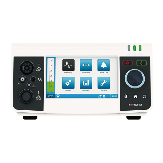
Device type 9LV203
CARAT II pro
Ventilator
User's manual
for physicians and medical professionals
as of device software 3.300
Advertisement
Table of Contents

Related Manuals for Hoffrichter CARAT II pro


Summary of Contents for Hoffrichter CARAT II pro
- Page 1 Mettenheimer Straße 12 / 14 19061 Schwerin Germany Telephone: +49 385 39925 - 0 Fax: +49 385 39925 - 25 CARAT II pro Email: info@hoffrichter.de www.hoffrichter.de Ventilator User’s manual for physicians and medical professionals as of device software 3.300 CARAT II pro Klinik ENG_2019-11-22_12.0...
- Page 3 The respiratory device may only be operated and maintained by trained personnel. The following documents are available for CARAT II pro in addition to this user's manual: • User's manual for CARAT II pro for patients •...
- Page 4 Keep the instructions in close proximity to the device for immediate re- ference if necessary. Every HOFFRICHTER GmbH device is supplied with a serial number for tracea- bility purposes. Please enter your device’s serial number here. You will find the serial number on the rating plate on the bottom of the device.
-
Page 5: Table Of Contents
TABLE OF CONTENTS CHAPTER 1 ................11 INTRODUCTION ...................11 Scope of delivery ...................12 Symbols ......................14 Intended purpose ...................19 User qualifications ..................21 CHAPTER 2 ................23 SAFETY INFORMATION ................23 General safety instructions ................24 Electrical safety ....................26 Installation requirements and transport ............27 Instructions before commissioning ..............29 Using of oxygen .....................29 Integration into IT networks ................30... - Page 6 Using oxygen ....................65 Determining oxygen concentration ..............71 Using the functional bag .................73 Switching the device on .................74 Switching the device off .................74 CHAPTER 5 ................75 VENTILATION MODES .................75 PCV mode ....................76 APCV mode ....................78 PSV mode .....................80 PSV-S mode ....................82 P-SIMV mode ....................84 VCV mode .....................86 AVCV mode ....................88...
- Page 7 CHAPTER 7 ................149 ALARMS AND MESSAGES ................149 General information ..................150 Alarm sound test ..................150 Audible alarm output (audio alarms) ..............151 Visible alarm output ..................152 Alarm log .....................154 Forwarding alarms ..................154 Alarm overview ....................155 Messages ....................160 CHAPTER 8 ................161 CLEANING AND DISINFECTION ..............161 Overview ......................162 Cleaning the device ..................164...
- Page 8 LIST OF FIGURES Figure 1: Rating plate ..................15 Figure 2: Connections at the front side of the device ........32 Figure 3: Connections at the rear side of the device ........33 Figure 4: Control elements ................35 Figure 5: LED displays ................37 Figure 6: Left device side ................39 Figure 7:...
- Page 9 Figure 37: PSV-S mode diagram ..............83 Figure 38: P-SIMV mode diagram ..............85 Figure 39: VCV mode diagram ..............87 Figure 40: AVCV mode diagram ..............89 Figure 41: V-SIMV mode diagram ..............91 Figure 42: CPAP mode diagram ..............92 Figure 43: Flow trigger (setting a percentage value) ........99 Figure 44: Inspiration trigger without SMART Function ........100 Figure 45: Inspiration trigger using SMART Function ........101 Figure 46: User profile in the toolbar ............107...
- Page 10 LIST OF TABLES Table 1: Operating time with battery power and factory default settings ..45 Table 2: Alarms for detecting a disconnection ..........55 Table 3: Overview of the ventilation and alarm parameter (adjustable) ....93 Table 4: Pressure increase times of the ramp ..........97 Table 5: Thresholds inspiratory trigger............98 Table 6: System Settings- Overview ............133 Table 7: Adjustable alarms ................155...
-
Page 11: Chapter 1
CHAPTER 1 INTRODUCTION This chapter contains general information on the use and operation of the ventilator. Chapter 1: Introduction... -
Page 12: Scope Of Delivery
SCOPE OF DELIVERY Illustration Name CARAT II pro Ventilator Switched-mode power supply Mains cable Disposable double line patient circuit for adults with pressure measuring tube (L = 180 cm, ∅ 22 mm) Adapter for bacterial filter SD card Straight FiO... - Page 13 Illustration Name Spare filter cassette, complete (open) with filters Spare coarse filter, 1 pack (2 ea) Spare fine filter, 1 pack (5 ea) User's manual for the patient Brief instructions Final inspection certificate Chapter 1: Introduction...
-
Page 14: Symbols
SYMBOLS PACKAGING SYMBOLS Symbol Meaning European Article Number Article number Serial number CE mark and number of the notified body. The medical device com- plies with the relevant requirements of the EU Directive 93/42/EEC for medical devices. Transport and store package with arrows pointing up at all times Fragile contents Protect from moisture! Humidity range during storage and transport... -
Page 15: Figure 1: Rating Plate
SYMBOLS ON THE RATING PLATE The rating plate is on the back of the device Ventilator Type: 9LV203 Quality makes the Difference CARAT II pro Li-Ion ICR 18650 14.8V; 4400mAh; 65.12Wh DC-INPUT -INPUT EAG1300001 max. 5A max. 15l/min max. 10A... - Page 16 SYMBOLS ON THE DEVICE Symbol Meaning General Follow the user's manual. Connecting points Inspiration tube connection Expiration tube connection Control tube connection Pressure measuring tube connection sensor connection DC connection sensor connection Com-interface Remote alarm/nurse call connection USB interface connection Chapter 1: Introduction...
- Page 17 Symbol Meaning output SD card slot Operation Alarm key ON/OFF key Safe key Home key Escape key LEDs Alarm LED Mains LED Battery LED Chapter 1: Introduction...
- Page 18 SYMBOLS USED IN THIS USER’S MANUAL Important information is denoted by symbols in this user’s manual. Please ensure that you follow these instructions in order to avoid accidents, personal injury and material damage. In addition, the local accident prevention regulations and general safety regula- tions in force in the area of use must be observed.
-
Page 19: Intended Purpose
2 minutes. If the CARAT II pro is operated with an internal battery, it can continue to be operated without any interruption in the event of a power failure. - Page 20 INDICATION The CARAT II pro can be used for the following indications: • Obstructive ventilation disorders (e.g., COPD) • Restrictive ventilation disorders (e.g., scoliosis, thorax deformities) • Neurological, muscular and neuromuscular disorders (e.g., diaphragmatic paralysis) • Central respiratory regulation disorders Irrespective of the indications listed here, the device must always be used in accordance with the physician's individual diagnosis.
-
Page 21: User Qualifications
SIDE EFFECTS The following undesired side effects may occur in connection with artificial respiration: Invasive ventilation: • Complications due to tube / tracheal cannula Mask ventilation: • Pressure points and skin defects in the face • Eye irritation due to leaks •... - Page 22 Chapter 1: Introduction...
-
Page 23: Chapter 2
CHAPTER 2 SAFETY INFORMATION This chapter contains safety instructions on the following topics: • General safety instructions • Electrical safety • Installation and transport • Commissioning • Use of oxygen • Safety-related test Chapter 2: Safety warnings... -
Page 24: General Safety Instructions
GENERAL SAFETY INSTRUCTIONS In the event that the acoustic alarm fails during ventilation, the patient should be continuously monitored by qualified and trained healthcare professionals. The monitoring person must be able to take appropriate measures in the event of an alarm or in the event of device malfunction. - Page 25 • We recommend the use of the tube systems tested and approved for use by the manufacturer. Using other tube systems may lead to aberrant results. • Manufacturer tested and approved accessories are recom- mended for the device. If other accessories are used, this may lead to insufficient ventilation or the use of hazardous materials may lead to further, secondary complications.
-
Page 26: Electrical Safety
• Please ensure that the total resistance of the ventilation system does not exceed 6 hPa with a flow of 60 l/min for adults and 30 l/min for children. • Any modification to the device poses a threat to its reliability and is accordingly not permitted. -
Page 27: Installation Requirements And Transport
30 cm to any part of the CARAT pro, including cables specified by Hoffrichter GmbH. A non-observance may result in a reduction in the performance of the device. - Page 28 • The system must never be stored or transported at ambient temperatures under - 20 °C and over + 60 °C. • The device must not be exposed to direct sunlight. • Use of this device next to other equipment or with other equipment in a stacked form should be avoided, as this could result in an abnormal operation.
-
Page 29: Instructions Before Commissioning
• If the patient is supplied with oxygen via the device, the should be measured. • CARAT II pro offers a FiO measurement via the optional sensor. We recommend using this particular sensor exclusively. -
Page 30: Integration Into It Networks
• The oxygen supply should be stopped before the ventilation is interrupted. We further recommend that, after stopping the ventilation, the device is allowed to run for several respira- tory cycles without an oxygen supply. • In the event of an oxygen leak, the oxygen supply should be closed off immediately. -
Page 31: Chapter 3
CHAPTER 3 DESCRIPTION OF DEVICE This chapter describes the connections, operation and display elements of the device. Chapter 3: Description of device... -
Page 32: Front Side Connecting Points
FRONT SIDE CONNECTING POINTS Connections at the front side of the device Figure 2: Connection of tube circuit - inspiration The single line patient circuit or the inspiration section of a double line patient circuit is connected here. Refer to page 50 and page 51. Connection of FiO sensor cable Connect the FiO... -
Page 33: Rear Side Connecting Points
REAR SIDE CONNECTING POINTS Figure 3: Connections at the rear side of the device DC connection The power supply plug is connected here. Refer to page 42. Connection of SpO sensor A SpO sensor can be connected here. page 60. SD card slot An SD card an be inserted here. - Page 34 output Oxygen monitoring: This is the exit for excess oxygen from the oxygen valve of the unit when ven- tilation has been turned off. Pressure monitoring: Excess oxygen pressure is exhausted to the outside from this exit during oxy- gen therapy. This is the case, when the pressure is higher than 1 hPa above the set ventilation pressure setting.
-
Page 35: Control Elements
CONTROL ELEMENTS Figure 4: Control elements Alarm key The alarm key has several functions: Function Condition Action Confirm all current alarms Active alarms Press briefly Confirm no longer active alarms Stored alarms Press briefly Mute the audible alarm for 2 min Active alarms Press briefly (audio alarm pause) - Page 36 16 Multifunctional knob MFK Function Action Select another parameter Turn Set parameters Turn Press briefly Confirm parameter selection Confirm modified parameter value Press briefly Open adjustment window for graphs and loops in the Press briefly monitoring screen The MFK is backlit (only when "MFK brightness" > 0 %). The color of the light depends on the operating status or the alarm priority of the currently displayed alarm.
-
Page 37: Led Displays
LED DISPLAYS Figure 5: LED displays Alarm LED The alarm LED lights/flashes in the event of an alarm. It also provides infor- mation on the alarm priority. Color Status (light) Priority/Status Flashes HIGH Yellow Flashes MEDIUM Turquoise Glows steadily White Glows steadily Device boots Power LED... - Page 38 Battery LED The battery LED provides information on the state of the internal battery charge. Color Status (light) Battery charge state ≥ 60 % Green Glows steadily ≥ 20 % ... < 60 % Yellow Glows steadily Glows steadily ≥ 0 % ... < 20 % White Glows steadily Device boots...
-
Page 39: Movable And Removable Housing Parts
MOVABLE AND REMOVABLE HOUSING PARTS Figure 6: Left device side Figure 7: Right device side 24 Handle (pull-out) The handle may be pulled out for device transport. 25 Bottom flap Valve membrane (expiration) is located under the bottom flap, which must be replaced before every change of patient or maintenance work. - Page 40 Chapter 3: Description of device...
-
Page 41: Chapter 4
• Never operate the device without the air filter. • Only use Original HOFFRICHTER filters. If the device was previously in an environment where the air temperature was not the same as in the new operating location, allow approximately 1 hour until the temperatures have evened out before commissioning. -
Page 42: Setting Up The Device
SETTING UP THE DEVICE Place the device on a flat and stable surface. Make sure that the device is placed securely and that the air inlet at the rear of the device is not blocked. Make sure that the display and the LEDs are positioned in the user's field of vision during ventilation. -
Page 43: Figure 9: Mains Connection Via Power Supply Unit
2. Connect the mains cable to the power supply. 3. Insert the mains cable plug into the power socket (100 - 240 V, 50/60 Hz). A Power socket B Mains cable C Power supply D Power supply plug E DC connector socket Figure 9: Mains connection via power supply unit 4. -
Page 44: Figure 10: Start Screen
SW-Version 2.003 Quality makes the Difference 0x12 Primary Alarm Not Working A Software version B Error message Figure 10: Start screen If no errors were detected during the hardware test or the errors have been confirmed, the display will switch to the standby screen. The current level of battery charge will be displayed on the standby screen. -
Page 45: Table 1: Operating Time With Battery Power And Factory Default Settings
OPERATION WITH INTERNAL BATTERY The internal battery is exclusively used for power failures bridging and power supply when changing the power source. It must not be used as primary power source for ventilation. To prevent the internal battery from discharging, the device should stay con- nected to the mains power during standby times. - Page 46 POWER FAILURE During a power failure, the battery capacity display must be monitored and an alternative power source kept ready. For further details on the battery state display, please refer to page 38. If the power supply is interrupted by a power failure, the device is supplied with power via the internal battery.
-
Page 47: Figure 12: Akkupack Uni Base (Right) / Akkupack Uni Plus (Left)
If the battery pack is connected to the ventilator, the power LED glows green. At full capacity and factory settings, the AKKUPACK uni BASE enables CARAT II pro to operate for up to 8 hours. Using AKKUPACK uni BASE together with AKKU- PACK uni PLUS doubles operation time to up to 16 hours. -
Page 48: Figure 13: Connecting Akkupack Uni Base
CONNECTING EXTERNAL BATTERY "AKKUPACK uni BASE" Connect the AKKUPACK uni BASE to the device according to Figure 13. A DC port B DC cable for ventilation C DC out (device connection ) D AKKUPACK uni BASE Figure 13: Connecting AKKUPACK uni BASE Chapter 4: Commissioning... -
Page 49: Connecting The Tube Circuit
CONNECTING THE TUBE CIRCUIT The following decsribes it is described how to connect the tube circuit to the device. We recommend the use of bacterial filters, in particular for clinic operations, when using the device for more than one patient. Tubes and cables must always be positioned so that they cannot wrap around the neck or limbs of the patient, thus avoiding the risk of strangulation. -
Page 50: Figure 14: Connecting A Single Line Patient Circuit With Pressure Measur
CONNECTING A SINGLE LINE PATIENT CIRCUIT If the CARAT II pro ventilator is operated with a single line patient circuit, it must not be used as a life-supporting device. Connect the tube circuit to the device according to Figure 14 or Figure 15. -
Page 51: Figure 16: Connecting A Double Line Patient Circuit With Pressure Measur
CONNECTING A DOUBLE LINE PATIENT CIRCUIT Connect the tube circuit to the device according to Figure 16 or Figure 17. A Patient side connection B Pressure measuring tube C Expiration tube D Inspiration tube E + H Bacterial filters F + G Adapters for bacterial filters Figure 16: Connecting a double line patient circuit with pressure measuring tube Should you be using a tube circuit without pressure measuring tube (Figure 17), the circuit in use must be calibrated (see page 55). -
Page 52: Figure 18: Connecting The Humidifier - Single Line Patient Circuit
CONNECTING A HUMIDIFIER A humidifier is used to humidify and warm the breathing air. If you use a humidi- fier, be sure to follow the manufacturer's user's manual. The humidifier is integrated into the inspiration section. It should be positioned below the patient and the device, so that no water can accumulate in the patient's lung or in the device. -
Page 53: Figure 19: Connecting The Humidifier - Double Line Patient Circuit
Double line patient circuit During active humidification and if medication is administered via a nebu- lizer, a hydrophobic filter (e.g. Air-Guard Clear) must be used in the expira- tion branch to keep the expiration connector dry and avoid damage to the flow sensor. -
Page 54: Figure 20: Using Hme Filter - Double Line Patient Circuit With Pressure Measur
USING HME FILTERS If no humidifier is in operation during non invasive ventilation, we recommend to apply HME filter to moisten the respiratory gas. A "combination filter" of HME filter and bacterial filter is recommended (e.g. Medisize Hygrovent HMEF). When using HME filter, please observe the manufacturer instruction and follow the respective and recommended replacement intervals. -
Page 55: Setting An Alarm To Detect Disconnection Of The Tube System
SETTING AN ALARM TO DETECT DISCONNECTION OF THE TUBE SYSTEM When filters or other components are used in the tube system, an increased resis- tance is created which often prevents a disconnection from being detected. Con- sequently, the device does not give an alarm. This represents a life-threatening risk for patients who are dependent on ventilation. -
Page 56: Calibrating The Tube Circuit
CALIBRATING THE TUBE CIRCUIT The tube calibration must be performed only by using a tube system with- out measuring tube. A tube calibration should be performed after an interruption in the power supply (on/off switching when running on battery power) and if changes have been made to the circuit system. - Page 57 5. Press the MFK. Tube calibration begins. Calibrate Tube Run... Calibrate O Sensor -Monitoring Internal Alarm Volume Night Screen Meaurements Timer Screen Change Brightness Display Brightness LEDs 6. If the calibration was successful, "OK" will appear after a few seconds. If the calibration Brightness MFK was not successful, "Error"...
-
Page 58: Figure 21: "Measurement Without Pressure Tube" Message Box
USING THE DEVICE WITHOUT TUBE CALIBRATION If no calibration is performed, the last stored calibration data are used. During the initial commissioning, the standard calibration data are used. If you start the ventilation, following message box will be displayed. Attention! Tubeless Pressure Measurement! Stored Calibration Data are used. -
Page 59: Connecting The Alarm Box Or The Nurse Call
CONNECTING THE ALARM BOX OR THE NURSE CALL Connect the alarm box to the device as shown in Figure 22. A Alarm box B Remote alarm/nurse call connection C Alarm box cable Figure 22: Connecting alarm box Alarm boxes are available as an accessory (see page 197). An on-site nurse call can also be connected to the remote alarm/nurse call con- nection point as well. -
Page 60: Spo 2 Sensor Connection
SENSOR CONNECTION Connect the SpO sensor to the device as shown in Figure 23. The toolbar will then show the icon. If the sensor is connected to the patient, the oxygen saturation and heart rate are displayed in the monitoring screen; if ventilation is in progress, it will also show in the parameter screen. -
Page 61: Inserting The Sd Card
INSERTING THE SD CARD Insert the SD card into the SD card slot until it clicks into place as shown in Fig- ure 24. The toolbar will then show the icon. Figure 24: Inserting SD card SD and SDHC cards up to 32 GB may be used. More information on SD cards is available on page 179. -
Page 62: Removing The Sd Card Safely
REMOVING THE SD CARD SAFELY To remove the SD card: 1. Touch the SD card symbol in the toolbar. Set 1 Set 2 Set 3 Mode IPAP Remove SD-Card 20,0 PEEP Frequency Secured SD-Card Removal? Time Inspiration Ramp ... -
Page 63: Figure 26: Removing Sd Card
5. When this message box appears, you must remove the SD card. Information SD-Card can now be removed. Gently press the card into the SD card slot and remove the card. Figure 26: Removing SD card If you would like to remove the SD card after powering off the device, please note the following: Remove the SD card only when the device is turned off and is disconnected from the main power supply to ensure that the data storage of the SD-card... -
Page 64: Connecting A Pc
CONNECTING A PC By using the “easySET” PC software, service technicians can easily access the device and perform routine maintenance. The detailed procedure is described in the CARAT pro service manual. Connect the PC according to Figure 27 to the device. You will need a USB cable with a type B plug (see page 197). -
Page 65: Using Oxygen
USING OXYGEN Before using oxygen, the safety instructions must be read as of page 29. Oxygen may only be supplied during active ventilation. The supply of oxygen is possible in all ventilation modes. Please note that any changes to the ventilation parameters, as e.g. pressure, I:E, frequency, will lead to a change of the FiO concentration. - Page 66 MEASURING OXYGEN CONCENTRATION The oxygen concentration may be inconsistent when feeding in a fixed value oxy- gen flow (FlowO ). The inspirational oxygen concentration (FiO ) can vary depend- ing on pressure, ventilation pattern of the patient, mask or leakage. The oxygen concentration should therefore always be measured with a FiO sensor when oxy- gen is being supplied (see accessories on page 196).
- Page 67 4. Press the MFK. Calibrate Tube Calibrate Tube Calibrate O Calibrate O Sensor Sensor -Monitoring -Monitoring Internal Internal Alarm Volume Alarm Volume Night Screen Night Screen Meaurements Meaurements Timer Screen Change Timer Screen Change Brightness Display Brightness Display ...
- Page 68 STARTING THE SUPPLY OF OXYGEN Use only certified and clean oxygen sources. 1. Switch the device on. 2. Start ventilation and wait for several respiratory cycles. 3. Start supplying the oxygen. STOPPING THE SUPPLY OF OXYGEN Stop the supply of oxygen at the oxygen source. Continue ventilation for a number of respiratory cycles.
-
Page 69: Figure 29: Connecting The Fio 2 Sensor (Single Line Patient Circuit Example)
CALIBRATING THE FiO SENSOR Calibration is done in relation to the ambient air with an assumption of an oxygen content of 21 %. Automatic calibration when the device is switched on (recommended) When the device is switched on and you connect the FiO sensor to the device, the FiO sensor will be calibrated automatically. - Page 70 3. Navigate to the system screen using the MFK . Press the MFK. 4. Navigate to "Calibrate FiO Sensor" by turning the MFK. Calibrate Tube Calibrate O Sensor -Monitoring Internal Alarm Volume Night Screen Meaurements Timer Screen Change Brightness Display ...
-
Page 71: Determining Oxygen Concentration
DETERMINING OXYGEN CONCENTRATION The oxygen concentration (FiO ) in the patient's respiratory system depends on the flow rate (Flow O ) of the oxygen supply and the breathing minute ventilation (MV) of the patient. The following diagrams provide values for determining oxygen concentration at the frequencies of 15 bpm, 20 bpm and 25 bpm. - Page 72 f = 25 bpm Flow O [l/min] MV = 2.5 l/min MV = 5.0 l/min MV = 7.5 l/min MV = 10.0 l/min Example f = 25 bpm 11 l/min Flow O [l/min] MV = 2.5 l/min MV = 5.0 l/min MV = 7.5 l/min MV = 10.0 l/min At an oxygen flow rate of 11 l/min and a minute ventilation of approximately...
-
Page 73: Using The Functional Bag
If important device functions are not visible or are inaccessible, proper operation cannot be ensured. Ö Only use the original HOFFRICHTER functional bag. The functional bag protects the ventilator from mechanical damage or weathering during mobile use (eg on a wheelchair or walker). The functional bag is available as an accessory (see page 195). -
Page 74: Switching The Device On
SWITCHING THE DEVICE ON The tube circuit may be connected when the device is started up, but it may not yet be connected to the patient yet. If you are using oxygen therapy during ventilation, please note the section "Using oxygen" from page 65. To switch on the device: 1. -
Page 75: Chapter 5
CHAPTER 5 VENTILATION MODES The device has three types of ventilation modes: • Mandatory ventilation modes, where the device performs the respiratory work for the patient completely. • Augmented ventilation modes, where the device performs part of the respiratory work, alternating or over- lapping with the patient's breathing rate. -
Page 76: Pcv Mode
PCV MODE Pressure Controlled Ventilation Main features • Pressure controlled • Device triggered • Time controlled • Fixed frequency • No spontaneous breathing possible In this ventilation mode, the ventilation is exclusively controlled by the device. Spontaneous breathing on the patient’s part is not possible. The ventilation period is based on the set frequency and a defined I:E ratio. -
Page 77: Figure 34: Pcv Mode Diagram
IPAP PEEP t (s) Ⓜ Ⓜ Ⓜ Ⓜ t (s) IPAP = 20 hPa PEEP = 8 hPa I:E = 1:2 (2 s : 4 s) f = 10 bpm Ⓜ Mandatory ventilation Figure 34: PCV mode diagram Chapter 5: Ventilation modes... -
Page 78: Apcv Mode
APCV MODE Assisted Pressure Controlled Ventilation Main features • Pressure controlled • Device or patient triggered • Time controlled • Backup frequency • Spontaneous breathing possible In its ventilation parameters, the pressure controlled assisted ventilation is equal to the exclusively controlled ventilation. By setting an inspiration trigger, however, the patient can stop expiration by inspi- ration efforts once he reaches the trigger threshold and initiate the next inspira- tion phase. -
Page 79: Figure 35: Apcv Mode Diagram
IPAP PEEP t (s) Ⓜ Ⓐ Ⓜ Ⓜ Ⓐ t (s) IPAP = 20 hPa PEEP = 8 hPa I:E = 1:2 (2 s : 4 s) f = 10 bpm Spontaneous breathing Ⓜ Mandatory ventilation Ⓐ Pressure controlled, assisted ventilation Figure 35: APCV mode diagram Chapter 5: Ventilation modes... -
Page 80: Psv Mode
PSV MODE Pressure Supported Ventilation Main features • Pressure supported • Device or patient triggered • Flow controlled • Backup frequency • Spontaneous breathing possible Pressure supported ventilation is intended to support spontaneous breathing and to initiate mechanical ventilation whenever spontaneous breathing is absent. The inspiration pressure (IPAP) and the positive end-expiratory pressure (PEEP) define the range of pressure for ventilating the patient. -
Page 81: Figure 36: Psv Mode Diagram
Important settings Tips • Alarm limit • Adjustable "Minimum Volume" "High Inspiration Volume" • Adjustable "Additional Pressure" to • Alarm limit reach the minimum volume "Low Inspiration Volume" • Adjustable "Trigger Lock" of the • Alarm limit inspiration trigger "High Expiration Volume" •... -
Page 82: Psv-S Mode
PSV-S MODE Pressure Supported Ventilation-Spontaneous Using PSV-S the device responds only to spontaneous breathing of the patient. Main features • Pressure supported • Patient triggered • Flow controlled • Device will responds only to spontaneous breathing • Apnoea alarm In its ventilation parameters, the PVS-S mode is equal to the PSV mode. The PSV-S mode ventilation parameters adjustment options are the same as those of the PSV mode. -
Page 83: Figure 37: Psv-S Mode Diagram
➊ PEEP t (s) Ⓐ Ⓐ Ⓐ Ⓐ t (s) PS = 20 hPa PEEP = 8 hPa Spontaneous breathing ➊ t > Apnoea time Apnoea alarm Ⓐ Pressure controlled assisted ventilation Figure 37: PSV-S mode diagram Chapter 5: Ventilation modes... -
Page 84: P-Simv Mode
P-SIMV MODE Pressure Controlled Synchronized Intermittent Mandatory Ventilation Main features • Pressure controlled • Device or patient triggered • Time controlled • Fixed frequency • Spontaneous breathing possible The SIMV mode provides a combination of pressure controlled ventilation and pressure assisted spontaneous breathing. Pressure controlled ventilation is based on a defined respiratory rate and a defined inspiration time. -
Page 85: Figure 38: P-Simv Mode Diagram
Important settings Tips • Alarm limit • Adjustable "Trigger Lock" of the "High Inspiration Volume" inspiration trigger • Alarm limit • Minimum (Ti Min) and maximum "Low Inspiration Volume" (Ti Max) inspiration times are adjust- able • Alarm limit "High Expiration Volume" •... -
Page 86: Vcv Mode
VCV MODE Volume Controlled Ventilation Main features • Volume controlled • Device triggered • Time controlled • Fixed frequency • No spontaneous breathing possible In this ventilation mode, ventilation is controlled exclusively by the device. Spontaneous breathing on the patient’s part is not possible. The ventilatory period is based on the set frequency and requires a defined I:E ratio. -
Page 87: Figure 39: Vcv Mode Diagram
PEEP t (s) Ⓜ Ⓜ Ⓜ Ⓜ t (s) PEEP = 8 hPa V = 1 l I:E = 1:2 (2 s : 4 s) f = 10 bpm Ⓜ Mandatory ventilation Figure 39: VCV mode diagram Chapter 5: Ventilation modes... -
Page 88: Avcv Mode
AVCV MODE Assisted Volume Controlled Ventilation Main features • Volume controlled • Device or patient triggered • Time controlled • Backup frequency • Spontaneous breathing possible In its ventilation parameters, the volume controlled assisted ventilation is equal to the volume controlled ventilation (VCV). By setting an inspiration trigger, however, the patient can stop expiration by inspi- ration efforts once he reaches the trigger threshold and initiate the additional breathes. -
Page 89: Figure 40: Avcv Mode Diagram
PEEP t (s) Ⓜ Ⓐ Ⓜ Ⓜ Ⓐ t (s) PEEP = 8 hPa V = 1 l I:E = 1:2 (2 s : 4 s) f = 10 bpm Ⓜ Mandatory ventilation Ⓐ Volume controlled assisted ventilation Figure 40: AVCV mode diagram Chapter 5: Ventilation modes... -
Page 90: V-Simv Mode
V-SIMV MODE Volume Controlled Synchronized Intermittent Mandatory Ventilation Main features • Volume controlled • Device or patient triggered • Time controlled • Backup frequency • Spontaneous breathing possible V-SIMV is a combination of volume controlled ventilation (VCV) with possible pres- sure supported ventilations (PSV) during the expiration phases. -
Page 91: Figure 41: V-Simv Mode Diagram
10 s 10 s ∆t ∆t + t PEEP t (s) Ⓜ Ⓟ Ⓐ Ⓟ Ⓟ Ⓜ t (s) PS = 12 hPa PEEP = 8 hPa Frequency = 6 bpm Spontaneous breathing Expected time window = 5 s Ⓜ... -
Page 92: Cpap Mode
CPAP MODE Continous Positive Airway Pressure Main features • Pressure controlled • Independent respiration In the CPAP mode, the device provides continuous positive pressure. The patient must be able to breathe spontaneously. Druck Pressure = 8 hPa Figure 42: CPAP mode diagram Chapter 5: Ventilation modes... -
Page 93: Overview Of Ventilation Modes
OVERVIEW OF VENTILATION MODES The following table shows which ventilation and alarm parameters can be set in the ventilation modes. Table 3: Overview of the ventilation and alarm parameter (adjustable) Parameter • • • Tidal Volume • Pressure • • •... - Page 94 Table 3: Overview of the ventilation and alarm parameter (adjustable) Parameter • • • • • • • High Frequency • • • Low Frequency • • • • • • High Inspiration Volume • • • • • • Low Inspiration Volume •...
-
Page 95: Ventilation Parameters Pescription
VENTILATION PARAMETERS PESCRIPTION TIDAL VOLUME AVCV V-SIMV The tidal volume is the adjustable inspiration volume, which is applied to the pati- ent on each inspiration. The "Tidal Volume" setting is directly related to the "Max. Pressure" venti- lation parameters. When "Max. Pressure" has been set up too low, the set tidal volume may not be reached. - Page 96 PEEP APCV PSV-S AVCV P-SIMV V-SIMV The PEEP (= Positive End Expiratory Pressure) is the positive pressure which is available to the patient during expiration before starting the new inspiration. It can be spontaneous as well as mechanically controlled. FREQUENCY APCV AVCV P-SIMV...
-
Page 97: Table 4: Pressure Increase Times Of The Ramp
Ti Max PSV-S P-SIMV V-SIMV The "Ti Max" setting limits inspiration time so that a late switchover to the expi- ration phase is prevented and a better syncronization of patient and device can be achieved. Ti Min PSV-S P-SIMV V-SIMV Setting up the "Ti Min"... -
Page 98: Table 5: Thresholds Inspiratory Trigger
FLOW RAMP V-SIMV AVCV The flow ramp can be set in the volume controlled modes as a constant inspi- ration flow (level 1 ), as decelerating inspiration flow (level 2 , level 3 level 4 ) or as an accelerating/decelerating inspiration flow (level 5 ). -
Page 99: Figure 43: Flow Trigger (Setting A Percentage Value)
EXPIRATION TRIGGER PSV-S P-SIMV V-SIMV The expiration trigger is a flow trigger both in the case of using of a single line patient circuit and a double line patient circuit. The peak flow of the inspiration is measured with each breath. The setting of the expiration trigger defines the per- centage of the peak flow at which the ventilator switches over to expiration. -
Page 100: Figure 44: Inspiration Trigger Without Smart Function
SMART FUNCTION APCV PSV-S AVCV P-SIMV V-SIMV The "SMART Function" can be set to avoid auto triggering, which are cause by artefacts of the single line patient circuit expiration valve. These artifacts lead to a breath triggering in the absence of effort by the patient during expiration. Without SMART Function The inspiration trigger is initiated by artefacts. -
Page 101: Figure 45: Inspiration Trigger Using Smart Function
Using SMART Function The inspiration trigger is not initiated by artefacts. V (ml) Volume curve ΔT Trigger threshold t (s) V (ml) Triggering Trigger activity Suppression Δt false triggering Trigger threshold t (s) Artefacts Spontaneous breathing Trigger by patient (spontaneous breathing) Figure 45: Inspiration trigger using SMART Function If the "SMART Function"... - Page 102 MINIMUM VOLUME APCV PSV-S The minimum volume is the minimum tidal volume, which is considered as a vol- ume guarantee during a pressure controlled ventilation. ADDITIONAL PRESSURE APCV PSV-S The additional pressure is graduately added by 2 hPa to the IPAP or PS pressure until the set additional pressure is reached, if the minimum volume has not been reached in order to guarantee the set minimum volume.
-
Page 103: Description Of Alarm Parameters
DESCRIPTION OF ALARM PARAMETERS APNOEA ALARM PSV-S CPAP The "Apnoea Alarm" setting establishes the time when the "Apnoea" alarm will be triggered in case of an apnoea event. HIGH FREQUENCY APCV PSV-S AVCV P-SIMV V-SIMV CPAP If the measured frequency is higher than the "High Frequency" setting, the "High Frequency"... - Page 104 LOW EXSPIRATION VOLUMEN APCV PSV-S P-SIMV CPAP If the measured expiration volume is lower than the "Low Expiration Volume" set- ting, the "Low Expiration Volume" alarm will be triggered. HIGH MINUTE VENTILATION APCV PSV-S P-SIMV V-SIMV CPAP AVCV If the measured minute volume be higher than the "High Minute Ventilation" set- ting, the "High Minute Ventilation"...
- Page 105 HIGH SpO APCV PSV-S AVCV P-SIMV V-SIMV CPAP If the measured oxygen saturation is greater than the "High SpO " setting, then the "High SpO " alarm will be triggered. LOW SpO APCV PSV-S AVCV P-SIMV V-SIMV CPAP If the measured oxygen saturation is lower than the "Low SpO "...
- Page 106 Chapter 5: Ventilation modes...
-
Page 107: Chapter 6
CHAPTER 6 DEVICE OPERATION This chapter decribes the device operation in more detail. KEY LOCK The key lock function is designed to protect against the accidental changing of device settings. It deactivates all control functions, except: • ON/OFF key to start ventilation •... - Page 108 SETTING THE USER PROFILE To set the user profile: 1. Navigate to "System" in the home screen by turning the MFK : 2. Press the MFK. 3. Navigate to "User Profile" by turning the MFK. Date and Time 13.02.16 10:36 Number Ventilation Sets User Profile Clinic...
-
Page 109: Menu Structure
MENU STRUCTURE • Home screen Monitoring screen Measurements (p, V , MV, f, I:E, FiO , SpO , HF) Graphs (p, V, V, FiO Loops (V-Flow-Loop, p-V-Loop) Parameter screen Set 1 Set 2 Set 3 Alarm log screen System screen Statistics screen Service screen BASIC OPERATION... - Page 110 TOUCH SCREEN OPERATION The touch operation is a comfort feature for quick and intuitive menu con- trol. If the touch operation is not possible, the device can still be operated using the multifunction knob and the keys. The following operations can be initiated with the touch screen: Set 1 Set 2 Set 3...
- Page 111 Set 1 Set 2 Set 3 19,8 1:1,5 6,840 Mode IPAP 20,0 [hPa] [bpm] PEEP 0,570 0,570 Frequency Time Inspiration Leck. [l/min] Ramp Minimum Volume [bpm] [bpm] Sigh Function ...
-
Page 112: Basic Screen Layout
BASIC SCREEN LAYOUT Monitoring Parameter Alarm Log System Statistics Service 1:45 Low Frequency 22:33 A Pressure bar (during running ventilation) B Screen content C Toolbar D Active ventilation mode Figure 47: Basic screen layout Chapter 6: Device operation... -
Page 113: Explanation Of Toolbar Icons
EXPLANATION OF TOOLBAR ICONS Icon Meaning Clinic mode active Home mode active Alarm active Red icon → High priority alarm → Yellow icon Medium priority alarm Turquoise icon → Low priority alarm Audio alarm paused The audible alarm has been paused for 2 min. The audible alarm of even a new alarm event will also be paused for 2 min. - Page 114 Icon Meaning Trigger lock "On" Trigger lock momentarily active Switching on night screen (touch symbol) Switching off night screen (touch symbol) SD card is inserted into the device No SD card inserted into the device sensor connected PC is connected via the USB port Error detected Selecting this icon results in a list of all current errors (see "Error messages"...
-
Page 115: Enabling A Screen
ENABLING A SCREEN The following screens are accessible from the home screen: • Monitoring screen Monitoring measurements (numerical and graphs) • Parameter screen Ventilation and alarm parameters of the active ventilation mode • Alarm log screen Display of alarms with time stamp and measurements •... - Page 116 To enable a screen: 1. Navigate to the desired screen by turning the MFK. The selected screen icon → Black Icon not selected → Blue 2. Press the MFK to activate the selected screen. CHANGING THE TIMER SCREEN The factory default setting of "Time Screen Change" is 120 seconds. The device switches 120 seconds after the last operation to the following screens: •...
-
Page 117: Monitoring
MONITORING In the monitoring screen the ventilation parameters are shown in real-time. The monitoring screen is divided into three sections: • Measurements • Graphs • Loops MEASUREMENTS DISPLAY The "Measurements" section displays the following ventilation parameters when ventilation is running: •... -
Page 118: Figure 49: Monitoring Screen (Data), Factory Setting
How to call up to the data: 1. Navigate to "Monitoring" in the home screen by turning the MFK: 2. Press the MFK. Measurements Graphs Loops 19,8 1:1,5 6,840 [hPa] [bpm] 0,570 0,570 Leck. [l/min] [bpm] ... - Page 119 To configure the measured values: 1. Press the MFK. The first measured value box is marked. Measurements Graphs Loops 19,8 19,8 1:1,5 6,840 [hPa] [hPa] [bpm] 0,570 0,570 Leck. [l/min] [bpm] 22:33 2. Navigate to the measured value box that you would like to configure by tur- ning the MFK.
-
Page 120: Figure 50: Monitoring Screen (Graphs)
GRAPHS DISPLAY Depending on your settings, "Graphs" will graphically display the following venti- lation parameters during running ventilation: • Pressure (p), • Flow (V), • Volume (V) • Oxygen (FiO How to call up to the graphs: 1. Navigate to "Monitoring" in the home screen by turning the MFK: 2. -
Page 121: Figure 51: Monitoring Screen (Change The Parameters)
The graphs can be set as follows: • Number of graphs (1,2 or 3) • Type of graph parameter • Scaling • Timescale To change the graphs representation: 1. Press the MFK or touch the display. Measurements Graphs Loops [hPa] ... -
Page 122: Figure 52: Monitoring Screen (Freeze Graphs)
Freezing the real-time curve: 1. Press the pause symbol Measurements Graphs Loops [hPa] Flow [l/min] -300 -600 -300 -600 22:33 Figure 52: Monitoring screen (freeze graphs) 2. Press the start symbol to restart the real-time curve Chapter 6: Device operation... -
Page 123: Figure 53: Flow-Volume-Loop
DISPLAY LOOPS Depending on your settings, you may display the following loops graphically in "Loops", while ventilation is running: • Flow-Volume-Loop • Volume-Pressure-Loop Flow-Volume-Loop Measurement Graphs Loops Flow [ l/ min ] -100 [ l] 0,200 0,400 0,600... -
Page 124: Figure 55: Flow-Volume-Loop
How to call up to "Loops": 1. Navigate to "Monitoring" in the home screen by turning the MFK. 2. Press the MFK. 3. Navigate to "Loops" by turning the MFK. Measurement Graphs Loops Flow [l /m i n ] ... -
Page 125: Figure 56: Monitoring Screen (Change The Loop)
You can adjust the loop as follows: • Type of loop • Scaling To change the loop representation: 1. Press the MFK or touch the display. Measurement Graphs Loops Flow [l/m i n] Settings Type Flow/Volume Auto Scale ... -
Page 126: To Change Ventilator And Alarm Parameters
TO CHANGE VENTILATOR AND ALARM PARAMETERS The adjustable alarm parameters are marked with an orange bar in contrast to the ventilation parameters. You can find a list of all adjustable alarms on page 155. How to call up to the ventilator and alarm parameters: 1. - Page 127 How to change a ventilation or alarm parameter: 1. Select the set to be changed by turning the MFK. Set 1 Set 2 Set 3 Mode IPAP 20,0 PEEP Frequency Time Inspiration Ramp Minimum Volume 2. Press the MFK. ...
- Page 128 5. Change the setting by turning the MFK. Set 1 Set 2 Set 3 Mode IPAP 20,0 EPAP Frequency Time Inspiration Ramp Dependencies Minimum Volume 6. Press the MFK to confirm the new setting. ...
-
Page 129: Activating A Ventilation Set
ACTIVATING A VENTILATION SET How to call up to the set settings: 1. Navigate to "Parameter" in the home screen by turning the MFK 2. Press the MFK. Set 1 Set 2 Set 3 Mode IPAP 20,0 PEEP Frequency ... - Page 130 2. Press the MFK twice. Set 1 Set 2 Set 3 Activate Set Mode IPAP 20,0 PEEP Frequency Time Inspiration Ti Max 3. Change the setting to "Yes" by turning the MFK. Ti Min Set 1 Set 2 Set 3 ...
-
Page 131: Changing A Ventilation Mode During Ventilation
CHANGING A VENTILATION MODE DURING VENTILATION To change to ventilation mode: 1. Navigate to "Parameter" in the home screen by turning the MFK. 2. Navigate to the active ventilation set by turning the MFK. 3. Press the MFK twice. Set 1 Set 2 Set 3 Mode... -
Page 132: Display Of Stored Alarms
DISPLAY OF STORED ALARMS How to call up the alarm log screen: 1. Navigate to "Alarm log" in the home screen by turning the MFK. 2. Press the MFK. 3. You can scoll up and down the entries by turning the MFK. 04.07.13 Low Internal Battery 22:35... -
Page 133: System Settings
SYSTEM SETTINGS In the system screen basic device settings, calibrations and tightness check can be made. Selecting the system screen device information can be obtained. Table 6: System Settings- Overview Menu item Explanation Calibrate Tube Calibrating the connected tube circuit (see page 55) Calibrate O Sensor Calibrating the FiO... -
Page 134: Figure 60: System Screen
Table 6: System Settings- Overview Menu item Explanation Ventilation Hours Total Total ventilation hours (can be reset with PC software) Operating Counter Ventilation hours + Standby hours Blower Service in Number of hours after which the blower must be replaced SW-Version Software version of the device Serial Number... - Page 135 To change the system settings (e.g. alarm volume): 1. Navigate to the desired parameter by turning the MFK. Calibrate Tube Calibrate O Sensor -Monitoring Internal Alarm Volume Night Screen Measurements 2. Press the MFK. Timer Screen Change Calibrate Tube Brightness Display ...
- Page 136 Calibrare Sensore O Monitoraggio FiO Interno CHANGING THE DEVICE LANGUAGE Volume Allarme To change the device language setting: Schermo notturno Misurazioni 1. Navigate to the 10th menu item by turning the MFK. Modifica schermo timer Calibrare circuito paziente Luminosità...
- Page 137 DATE AND TIME CHANGES To change the date and time: 1. Navigate to "System" in the home screen by turning the MFK: 2. Press the MFK. 3. Navigate to "Date and Time" by turning the MFK. Date and Time 13.02.16 10:36 Number Ventilation Sets ...
- Page 138 6. Press the MFK. Date and Time Year 2016 13.02.16 10:36 Number Ventilation Sets Month User Profile Clinic Tightness Check Hour Recent Ventilation Hours Minute Ventilation Hours Total Operating Counter Blower Service in 14658 7. Change the setting by turning the MFK. SW-Version 1.000 ...
-
Page 139: Figure 61: Circuit Configuration Tightness Check Single Line Patient Circuit
PERFORMING A TIGHTNESS CHECK The tightness check serves to detect leaks in the the tube cicuit. Hold on to the end cap during the tightness check and do not direct the tube at anyone. To perform the tightness check: 1. Connect the tube circuit to the device. A End cap (supplied with the tube circuit) B Expiration valve C Control tube D Ventilation tube E Pressure measuring tube Figure 61: Circuit configuration tightness check single line patient circuit... - Page 140 2. Navigate to the home screen by turning the MFK to "System": 3. Press the MFK. 4. Navigate to "Tightness Check" by turning the MFK. 5. Press Datum und Uhrzeit 22,7 13.02.16 10:36 Anzahl der Beatmungssets Flow [ hPa] [ l/min] ...
- Page 141 RESETTING VENTILATION HOURS The ventilation operational period is displayed in the system screen as "Total Venti- lation Hours". In addition, there is a ventilation hours counter, which can be reset by the user. The counter is located in the system screen as "Recent Ventilation Hours“. To reset the ventilation hours: 1.
-
Page 142: Statistics
STATISTICS The statistics screen contains statistical evaluations of the following ventilation parameters. • Minute volume • Frequency • SpO • Leak Rate • Tidal Volume • I:E Ratio The evaluation of the ventilation parameters is based on percentiles. Percentiles are the dispersion measurement of the statistical data distribution during ventila- tion sessions. -
Page 143: Figure 63: Statistics Screen (1 Ventilation Parameter)
How to call up to the statistical values: 1. Navigate to the home screen by turning the MFK to "System": 2. Press the MFK. [ bpm ] Jan/16 Feb/16 08 09 10 11 12 13 14 15 16 17 18 19 20 21 22 23 24 25 26 27 28 29 30 31 01 02 03 04 05 06 22:33 Figure 63: Statistics screen (1 ventilation parameter) Chapter 6: Device operation... -
Page 144: Figure 64: Statistics Screen (2 Ventilation Parameter)
In the statistics screen you can set if the statistics of 1 or 2 ventilation parameters are to be displayed. Setting for statistics to be displayed: 1. Press the MFK or touch the display. 8,000 [ l ] 6,000 Settings 4,000 2,000... -
Page 145: Night Screen
NIGHT SCREEN In a dark environment, the brightness of the display is often perceived as distur- bing. The night screen provides a remedy. Due to the reduced backlighting, the display no longer shines as brightly. Furthermore, the MFK lighting is deactivated and the mains LED and the battery LED are darkened. - Page 146 To change the layout of the night screen: 1. Navigate to the home screen by turning the MFK to "System". 2. Press the MFK. 3. Navigate to "Night Screen" by turning the MFK and then press the MFK. 4. Change the parameter by turning the MFK to "Measurements", "Light" or "Dark".
-
Page 147: Starting Ventilation
STARTING VENTILATION The expiration valve air outlet has to be open during running ventilation. Make sure that the opening is not blocked as the expired air will be unable to escape and will affect the ventilation process. 1. Switch on the device using the main power switch on the rear of the device 2. - Page 148 Chapter 6: Device operation...
-
Page 149: Chapter 7
CHAPTER 7 ALARMS AND MESSAGES This chapter describes alarms and messages, their cause, and what measures need to be taken in case of an alarm event. Chapter 7: Alarms and messages... -
Page 150: General Information
The device must be operated so that the alarm is audible and visible by the user. Audible alarms can be forwarded using the nurse call or the alarm box. The CARAT II pro ventilator is equipped with fixed and adjustable alarms, relating to the respective ventilation modes. -
Page 151: Audible Alarm Output (Audio Alarms)
AUDIBLE ALARM OUTPUT (AUDIO ALARMS) Audio alarms are issued in a sequence of beeps. Alarm tones differ depending on alarm cause and priority. For more information, please see page 155. If the alarm sound equipment is defective and emits no sound, the audible alarms will be triggered by a second alarm sound transmitter which emits only a simple audible alarm. -
Page 152: Visible Alarm Output
AUDIO ALARMS VOLUME The audio alarm volume can be set to 3 levels in the system screen: • Level 1 → low volume (55 dB) • Level 2 → medium volume (60 dB) • Level 3 → high volume (65 dB) The volume of levels 1 and 2 are automatically raised to a level 3 in case the alarm event still exists after 1 minute of audible alarm. -
Page 153: Figure 70: Alarm Output In The Toolbar
System Statistics Service 1:45 Low Frequency 22:33 A "Alarm active" icon B Alarm Figure 70: Alarm output in the toolbar ALARM OUTPUT AS A TEXTBOX 120 seconds after the last performed operation the alarms will also display in a textbox as well. The textbox will disappear as soon as you press the alarm key. The textbox color corresponds to the highest priority alarm: •... -
Page 154: Alarm Log
The alarms will be forwarded without delay to the nurse call or the alarm box. Instructions on how to connect the HOFFRICHTER alarm box or nurse call can be found on page 59. Figure 72: Alarm box The alarm box is an optional accessory to facilitate remote output of the alarm. -
Page 155: Alarm Overview
ALARM OVERVIEW ADJUSTABLE ALARMS The adjustable alarms are physiologically conditional alarms. You can set the alarm limits in the parameter screen (see page 126). Table 7: Adjustable alarms Alarm Priority Audible LED alarm Cause Time delay alarm Status Apnoea HIGH c a f –... - Page 156 Table 7: Adjustable alarms Alarm Priority Audible LED alarm Cause Time delay alarm Status High MEDIUM c a f Yellow - Measured frequency is for 3 breaths in Frequency flashes higher than the "High a row Frequency" MEDIUM c a f Yellow - Measured frequency for 3 breaths in...
-
Page 157: Table 8: Fixed Alarms
FIXED ALARMS The fixed alarms are technically conditional alarms. Alarm conditions are built into the device and are non-adjustable by the user. Table 8: Fixed Alarms Alarm Priority Audible State of the Cause Correction alarm alarm LED Error HIGH c c c – c c Red - Defective battery Device must be... - Page 158 Table 8: Fixed Alarms Alarm Priority Audible State of the Cause Correction alarm alarm LED Over MEDIUM c a f Yellow - Over pressure Device must Pressure flashes detected be serviced, throughout 3 or check if the breaths or 15s alarm may have been triggered by the patient...
- Page 159 Table 8: Fixed Alarms Alarm Priority Audible State of the Cause Correction alarm alarm LED Error FiO MEDIUM C b a Yellow - sensor Connect the FiO sensor flashes disconnected sensor to the from the decice device Check MEDIUM C b a Yellow - sensor Connect the...
-
Page 160: Messages
Monitoring Parameter Alarm Log MESSAGES MESSAGE DISPLAY IN THE TOOLBAR Messages are displayed in the toolbar. When an alarm occurs, the alarm is dis- System Statistics Service played instead of the message, since the alarm has a higher priority. ... -
Page 161: Chapter 8
CHAPTER 8 CLEANING AND DISINFECTION • Before cleaning the device, remove the power plug from the power supply. • If ventilation is running, insert a spare coarse filter for the duration of the cleaning or insert a complete replacement filter cassette into the device. -
Page 162: Overview
OVERVIEW The following overview table describes the cleaning intervals of articles delivered by HOFFRICHTER. For articles by other manufacturers, please follow their clean- ing instructions. Table 10: Cleaning intervals - overview Component Name Clean Disinfect Replace CARAT II pro With every... - Page 163 Table 10: Cleaning intervals - overview Component Name Clean Disinfect Replace Filter cassette With every (without filter) needed new patient Course filter Weekly Instead of cleaning, when patient changes Fine filter Monthly, if severely contaminated, or for a patient change sensor In accordance needed...
-
Page 164: Cleaning The Device
CLEANING THE DEVICE Domestic use For cleaning the surface of the device, use a cloth moistened with soapy water. Then wipe with a cloth moistened with clear water in order to remove any remain- ing of the soapy water. The device must be completely dry before commissioning. Clinical use Disinfect the device surface on a regular basis, or when there is any possi- bility of contamination. -
Page 165: Cleaning The Headgear
CLEANING THE HEADGEAR 1. Disconnect the headgear from the mask. 2. Clean the headgear as described in the headgear manufacturer's users'manual. CLEANING / REPLACING THE FILTER A Filter frame cover B Filter cassette C Fine filter (white) D Coarse filter (black) Figure 74: Filter cassette structure CLEANING THE COARSE FILTER 1. - Page 166 REPLACING THE FINE FILTER The white fine filter cannot be cleaned. It must be replaced with a new one. 1. Pull the filter cassette from the device. 2. Remove the coarse filter (black). 3. Remove the fine filter (white) and replace it with a new one. 4.
-
Page 167: Using The Device For More Than One Patient
USING THE DEVICE FOR MORE THAN ONE PATIENT If the device is intended for use by more than one patient (e.g., in operation in clinics), a suitable bacterial filter (e.g., MEDISIZE BARR-VENT S) should be used continuously to protect the device from contamination by human pathogens. The bacterial filter must be changed daily. - Page 168 Chapter 8: Cleaning and disinfection...
-
Page 169: Chapter 9
CHAPTER 9 ROUTINE CHECKS AND MAINTENANCE WORK Routine checks and scheduled maintenance are necessary in order to maintain safe functioning of the device. This chapter describes which and when tests and maintenance works must be performed. You must not perform any testing or maintenance work while the patient is still connected to the device. -
Page 170: Overview
OVERVIEW Table 11: Service intervals - overview When? What? By whom? Before commissioning Provider/Service Safety-related test (see page 171) Weekly Clean/replace the coarse filter User (see page 165) Visually check of the fine filter User Monthly, or before, if heavily Replace fine filter User contaminated... -
Page 171: Safety-Related Test (Srt)
SAFETY-RELATED TEST (SRT) All procedures performed are to be recorded. To maintain and check the device functions, the device must be subjected to an safety-related test every two years, carried out by an authorized service technician. The safety-related check comprises: •... -
Page 172: Replacing The Valve Membrane (Expiration)
REPLACING THE VALVE MEMBRANE (EXPIRATION) When? By whom? • Every 6 months, if the device is Provider/Service operated without bacterial filter Bottom flap B Valve cover C Valve membrane Figure 75: Replacing valve membrane (expiration) Replace the valve membrane as follows: 1. -
Page 173: Battery Maintenance
BATTERY MAINTENANCE The batteries in CARAT II pro are powerful lithium-ion batteries. To obtain the full capacity of the batteries it is important to charge and maintain them on a regular basis. The number of charging cycles of lithium-ion batteries is limited. Therefore the batteries must be replaced and disposed, when the battery quick test fails or at the latest after 2 years. - Page 174 PERFORM THE BATTERY QUICK TEST The battery quick test verifies whether the device in case of a power failure can be operated on battery for at least one hour. When the device is used the battery quick test must be performed out by the provider or user every 6 months. How- ever, a monthly check is recommended.
-
Page 175: Chapter 10
CHAPTER 10 APPENDIX Chapter 10: Appendix... -
Page 176: Instructions For Ventilation Outside Of Aclinical Setting
TECHNICAL SPECIFICATIONS FOR THE DEVICE ESSENTIAL PERFORMANCE FEATURES The essential performance features of the CARAT II pro are: • pressure-controlled mechanical support with a pressure accuracy of ± (2 % of the scale value + 8 % of the actual measured value), •... -
Page 177: Figure 76: Block Diagram For The Device
(EN 60601-1-2: 2015 Chapter 8.1, section 18) The essential performance features can be affected by EMC interferences (see sec- tion "Manufacturer’s declaration on electromagnetic compatibility" on page198). IMPORTANT COMPONENTS The CARAT II pro ventilator comprises the following components: Remote alarm / Accessories SD card... -
Page 178: Figure 77: Pneumatic Block Diagram
PNEUMATIC BLOCK The pneumatic block is the connector unit for the double- or single line circuit and consists of the following components: Oxygen Pressure sensor connection Oxygen valve Pressure Oxygen measuring output tube connection (ø = 3.5 mm) Pressure switch Valve membrane Flow Tube circuit... -
Page 179: Data Management
DATA MANAGEMENT The device has an internal memory to recording data. We recommend operat- ing the device with an SD card to save larger amounts of data. More information about SD cards are available on page 61. The following data will be saved: Table 12: Data management Data and parameters Inside the device... -
Page 180: Error Messages
ERROR MESSAGES Table 13: Error messages during operation and at device start-up Error message Cause Correction Error SpO sensor Communication to SpO Device must be serviced measuring module not possible sensor defective Replace SpO sensor SD card is full No storage space avail- Insert blank SD card able on the SD card Flash Not Working... - Page 181 Error message “Default Parameters Loaded” If the error “Default Parameters Loaded” occurs, an error window appears: Error Loading of Parameters failed Apply Default Parameters ? If the boot process is initialized during ventilation, ventilation continues. However, the device can no longer be operated. The user now has the following options: •...
-
Page 182: Technical Data
TECHNICAL DATA The manufacturer reserves the right to make technical changes without notice. Power supply Mains operation 100...240 V AC (-20 %, +10 %), 50...60 Hz DC operation 12 V DC / 10 A or 24 V DC / 5 A Internal battery operation Lithium ion battery, 14.8 V (nominal voltage) / 4.4 Ah / 65.12 Wh... - Page 183 Storage and transport conditions Relative humidity 5 % ... 95 %, non-condensing Air pressure range 250 hPa ... 1100 hPa Storage conditions Store in a dry, vibration-free place, in an upright position; store device and accessories in their origi- nal packaging. Sound pressure range of audible alarm signal (at 1 m distance) Lowest value 55 dBA, Level 1...
- Page 184 Measured values Parameter Display area Display Measurement Accuracy increments Pressure 0 – 100 hPa 0.1 hPa 0.0 – 1.0 hPa or 5 % of the 100 hPa measured value Pressure 0 – 60 hPa 15 Pa 0.0 – 1.0 hPa or 5 % of the 100 hPa measured value Volume...
-
Page 185: Settings Ranges And Control Accuracy
SETTINGS RANGES AND CONTROL ACCURACY VENTILATION PARAMETERS Table 14: Setting ranges and control accuracy of ventilation parameters Parameter Setting range Setting Accuracy incre- ments Tidal Volume 0.05 – 2 l [V < 1,5 l/s x 0.01 l 0.03 l or 20 % of the measured value inspiration time] Pressure... -
Page 186: Table 15: Setting Ranges And Control Accuracy Of Alarm Parameters
Table 14: Setting ranges and control accuracy of ventilation parameters Parameter Setting range Setting Accuracy incre- ments Additional Pressure 3 – 10 hPa [Additional 0.5 hPa 1,0 hPa or 5 % of the Pressure ≤ 50 hPa – measured value IPAP] Max. - Page 187 Table 15: Setting ranges and control accuracy of alarm parameters Parameter Setting range Setting Accuracy incre- ments High FiO Off; 30 – 100% Low FiO Off; 18 – 90 % High SpO Off, 70 – 100 % [min. 1 % greater then "Low SpO "] Low SpO...
-
Page 188: Factory Settings
FACTORY SETTINGS VENTILATION PARAMETERS Table 16: Factory settings of ventilation parameter Mode PCV (Set 1) PSV (Set 2) P-SIMV (Set 3) Parameter IPAP 20 hPa 20 hPa 20 hPa PEEP 5 hPa 5 hPa 5 hPa Frequency 12 bpm 12 bpm 12 bpm Time Inspiration Ti Max... -
Page 189: Table 17: Factory Settings Of Alarm Parameter
ALARM PARAMETERS Table 17: Factory settings of alarm parameter Mode PCV (Set 1) PSV (Set 2) P-SIMV (Set 3) Parameter High Frequency 30 bpm 30 bpm 30 bpm Low Frequency 4 bpm High Inspiration Volume Low Inspiration Volume 0.2 l 0.2 l 0.2 l High Expiration Volume... -
Page 190: Table 18: Factory Settings Of Device Parameters
DEVICE PARAMETERS Table 18: Factory settings of device parameters Parameter Factory setting Setting range Setting increments -Monitoring Internal Internal, External Alarm Volume 1 – 3 Night Screen Measurements Measurements, Light, Dark Timer Screen Change 2 min Off, 20 s – 100 s: 20 s –... - Page 191 STANDARDS The device complies with the following standards: • DIN EN 60601-1-2 Medical electrical equipment - Part 1-2: General requirements for basic safety and essential performance - Collateral standard: Electromagnetic compatibility - Requirements and tests (IEC 60601-1-2:2007, modified) • DIN EN 60601-1-4 Medical electrical equipment - Part 1-4: General requirements for safety;...
-
Page 192: Replacement Parts And Accessories
REPLACEMENT PARTS AND ACCESSORIES Make sure to follow all general safety guidelines when using replacement parts and accessories page 24. For ordering of replacement parts and accessories, please contact a HOFFRICH- TER service partner. REPLACEMENT PARTS Name Figure Article number Disposable two-hose system with optionally usable pressure measuring hose and Velcro fastener (L = 180 cm, ∅... - Page 193 Coarse filter, 1 pack (2 ea) 00014950 Course filter 00002993 Fine filter, 1 pack (5 ea) 00014951 Fine filter 00002994 User's manual for CARAT II pro for physicians and medical professionals 50000625 User's manual for CARAT II pro for patients 50000626 Chapter 10: Appendix...
- Page 194 Name Figure Article number Brief instructions for CARAT II pro 50000645 Carrying case 00004875 Chapter 10: Appendix...
- Page 195 ACCESSORIES Name Figure Article number Disposable single-tube system with exhalation valve, control line and optionally usable pressure measuring tube (L = 180 cm, ∅ 22 mm) 00014970 Disposable two-hose system with optionally usable pressure measuring hose and Velcro fastener (L = 180 cm, ∅ 22 mm) 00014972 Disposable single-tube system with exhalation valve, control line and optionally usable pressure measuring tube...
- Page 196 Name Figure Article number Masks Size XS Size S Size M Size L Size XL Standard NIPPV 00003461 00003442 00003438 0003462 Full Face Mask Standard NIPPV Full Face Mask 00003439 autoclavable Cirri Comfort 00003489 00003490 00003491 Full Face Mask NIPPV measurement set consisting of: sensor, T-adapter, FiO sensor adapter, FiO...
- Page 197 Name Figure Article number Cover for expiration tube connection 42100449 USB cable (PC cable) 00005291 AKKUPACK uni BASE "Ventilation" 00011100 AKKUPACK uni PLUS 00011099 Remote alarm box, complete including accessories 00014122 Remote alarm box without accessories 00004834 Cable for remote alarm box 00014115 Cable for nurse call 00014117...
-
Page 198: Manufacturer's Declaration On Electromagnetic Compatibility
Guidance and manufacturer’s declaration – electromagnetic emissions The CARAT II pro ventilator is intended for use in the electromagnetic environment spec- ified below. The user of the CARAT II pro ventilator should ensure that it is used in such an environment. - Page 199 Guidance and manufacturer’s declaration – electromagnetic immunity The CARAT II pro ventilator is intended for use in the electromagnetic environment spec- ified below. The user of the CARAT II pro ventilator should ensure that it is used in such an environment.
- Page 200 > 95 % dip in U pital environment. If the input lines acc. to 1 cycle 1 cycle user of the CARAT II pro IEC 61000-4-11 ventilator requires con- 30 % dip in U 30 % dip in U tinued operation during...
-
Page 201: Disposal
DISPOSAL Proper disposal saves natural resources and prevents harmful substances being released into the environment. DEVICE The device must not be disposed of with the household waste. Please contact the relevant customer services department to find out how to dispose of the device, etc. properly. BATTERIES Replaced batteries must be disposed in accordance with the respective local laws. -
Page 202: Disclaimer
DISCLAIMER HOFFRICHTER GmbH accepts no liability for consequences in terms of safety, reliability and performance of the product if: • interventions, modifications, extensions, calibration, repairs and maintenance are carried out by persons not authorized by us, • other manufacturers’ accessories and spare parts are used that have not been approved by us for use on the product, •...
Need help?
Do you have a question about the CARAT II pro and is the answer not in the manual?
Questions and answers