Table of Contents
Advertisement
Quick Links
Advertisement
Table of Contents

Related Manuals for Texas Instruments PFCLLCSREVM034


Summary of Contents for Texas Instruments PFCLLCSREVM034
- Page 1 PFCLLCSREVM034 User Guide User's Guide Literature Number: SLUUC46 June 2020...
-
Page 2: Table Of Contents
......................Load Transient ....................LLC Loop Response ....................9.10 Steady State Waveforms ....................9.11 X Capacitor Discharge ......................Assembly Drawings ......................... List of Materials Table of Contents SLUUC46 – June 2020 Submit Documentation Feedback Copyright © 2020, Texas Instruments Incorporated... - Page 3 List of Figures ..............PFCLLCSREVM034 Schematic Diagram: PFC Section ............... PFCLLCSREVM034 Schematic Diagram: LLC Section ................PFCLLCSREVM034 Test Setup Diagram ....................Efficiency vs Output Current ................... Power Factor vs Output Power ....................THD vs Output Current ..................Output Voltage vs Output Current ....
- Page 4 List of Tables ............PFCLLCSREVM034 Electrical Performance Specifications ........................Test Points ......................List of Terminals ....................Efficiency Measurements ................... Standby Power Measurements ......................List of Materials List of Tables SLUUC46 – June 2020 Submit Documentation Feedback Copyright © 2020, Texas Instruments Incorporated...
- Page 5 Any other use and/or application are strictly prohibited by Texas Instruments. If you are not suitable qualified, you should immediately stop from further use of the HV EVM.
- Page 6 EVM in an adequate lucent plastic box with interlocks from accidental touch. Limitation for safe use: EVMs are not to be used as all or part of a production unit. List of Tables SLUUC46 – June 2020 Submit Documentation Feedback Copyright © 2020, Texas Instruments Incorporated...
-
Page 7: Trademarks
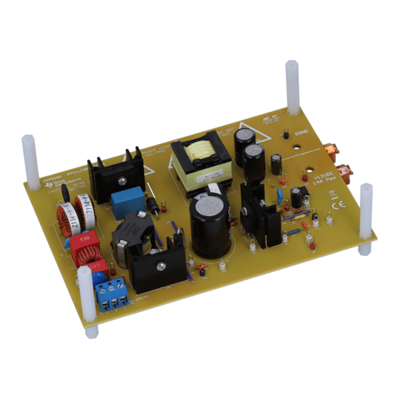
All trademarks are the property of their respective owners. Introduction The purpose of the PFCLLCSREVM034 is to aid in evaluation of the UCC256404 LLC resonant controller, UCC28056B transition mode PFC controller and UCC24624 dual channel synchronous rectification controller. The EVM features a transition mode boost PFC front end and isolated half bridge LLC converter with synchronous rectification. -
Page 8: Performance Specifications
Performance Specifications www.ti.com Performance Specifications Table 1. PFCLLCSREVM034 Electrical Performance Specifications PARAMETER TEST CONDITIONS UNITS Input Characteristics AC Voltage Range Vrms AC Voltage Frequency Output Characteristics Output Voltage Output Current System Characteristics No Load Standby 115-Vrms Input 84.90 Power No Load Standby 230-Vrms Input 113.59... -
Page 9: Schematic Diagram
Schematic Diagram www.ti.com Schematic Diagram Figure 1. PFCLLCSREVM034 Schematic Diagram: PFC Section SLUUC46 – June 2020 PFCLLCSREVM034 User Guide Submit Documentation Feedback Copyright © 2020, Texas Instruments Incorporated... -
Page 10: Pfcllcsrevm034 Schematic Diagram: Llc Section
Schematic Diagram www.ti.com Figure 2. PFCLLCSREVM034 Schematic Diagram: LLC Section PFCLLCSREVM034 User Guide SLUUC46 – June 2020 Submit Documentation Feedback Copyright © 2020, Texas Instruments Incorporated... -
Page 11: Test Points
Table 3. List of Terminals TERMINAL NAME DESCRIPTION AC Input 3-pin, AC power input, 90–264 V VOUT Output voltage positive terminal SGND Output voltage ground terminal SLUUC46 – June 2020 PFCLLCSREVM034 User Guide Submit Documentation Feedback Copyright © 2020, Texas Instruments Incorporated... -
Page 12: Test Setup
Recommended Wire Gauge: Capable of 25 A, or better than #14 AWG, with the total length of wire less than 8 feet (4 feet input and 4 feet return). Recommended Test Setup Figure 3. PFCLLCSREVM034 Test Setup Diagram PFCLLCSREVM034 User Guide SLUUC46 – June 2020 Submit Documentation Feedback Copyright ©... -
Page 13: Performance Data And Typical Characteristics Curves
79.56% 86.61% 89.66% 90.15% 89.76% 89.05% 80.96% 88.11% 90.17% 91.05% 90.86% 90.05% 80.60% 89.21% 92.63% 92.95% 92.76% 91.89% 80.59% 89.51% 92.32% 93.50% 92.14% 92.14% SLUUC46 – June 2020 PFCLLCSREVM034 User Guide Submit Documentation Feedback Copyright © 2020, Texas Instruments Incorporated... -
Page 14: Standby Power
84.896 324.54 558.78 113.594 348.06 574.90 Power Factor Figure 5 illustrates the power factor vs output current. Figure 5. Power Factor vs Output Power PFCLLCSREVM034 User Guide SLUUC46 – June 2020 Submit Documentation Feedback Copyright © 2020, Texas Instruments Incorporated... -
Page 15: Total Harmonic Distortion
Performance Data and Typical Characteristics Curves www.ti.com Total Harmonic Distortion Figure 6 summarizes the total harmonic distortion vs output current. Figure 6. THD vs Output Current SLUUC46 – June 2020 PFCLLCSREVM034 User Guide Submit Documentation Feedback Copyright © 2020, Texas Instruments Incorporated... -
Page 16: Load Regulation
Performance Data and Typical Characteristics Curves www.ti.com Load Regulation Figure 7 illustrates the output voltage regulation performance vs output current. Figure 7. Output Voltage vs Output Current PFCLLCSREVM034 User Guide SLUUC46 – June 2020 Submit Documentation Feedback Copyright © 2020, Texas Instruments Incorporated... -
Page 17: Startup
Figure 8. 115Vrms Input Startup into No Load (CH1=PFC Output; CH2=AC Input; CH3=LLC Output) Figure 9. 115Vrms Input Startup into No Load Zoomed In (CH1=PFC Output; CH2=AC Input; CH3=LLC Output) SLUUC46 – June 2020 PFCLLCSREVM034 User Guide Submit Documentation Feedback Copyright © 2020, Texas Instruments Incorporated... -
Page 18: 115Vrms Startup Into Full Load (Ch1=Pfc Output; Ch2=Ac Input; Ch3=Llc Output)
Figure 10. 115Vrms Startup into Full Load (CH1=PFC Output; CH2=AC Input; CH3=LLC Output) Figure 11. 115Vrms Startup into Full Load Zoomed In (CH1=PFC Output; CH2=AC Input; CH3=LLC Output) PFCLLCSREVM034 User Guide SLUUC46 – June 2020 Submit Documentation Feedback Copyright © 2020, Texas Instruments Incorporated... -
Page 19: 230Vrms Input Startup Into No Load (Ch1=Pfc Output; Ch2=Ac Input; Ch3=Llc Output)
Figure 12. 230Vrms Input Startup into No Load (CH1=PFC Output; CH2=AC Input; CH3=LLC Output) Figure 13. 230Vrms Startup into No Load Zoomed In (CH1=PFC Output; CH2=AC Input; CH3=LLC Output) SLUUC46 – June 2020 PFCLLCSREVM034 User Guide Submit Documentation Feedback Copyright © 2020, Texas Instruments Incorporated... -
Page 20: 230Vrms Input Startup Into Full Load (Ch1=Pfc Output; Ch2=Ac Input; Ch3=Llc Output)
Figure 14. 230Vrms Input Startup into Full Load (CH1=PFC Output; CH2=AC Input; CH3=LLC Output) Figure 15. 230Vrms Startup into Full Load Zoomed In (CH1=PFC Output; CH2=AC Input; CH3=LLC Output) PFCLLCSREVM034 User Guide SLUUC46 – June 2020 Submit Documentation Feedback Copyright © 2020, Texas Instruments Incorporated... -
Page 21: Output Ripple
Figure 16. No Load Output Ripple (CH3=LLC Output AC Coupled) Figure 17 illustrates the LLC output voltage ripple at full load. Figure 17. Full Load Output Ripple (CH3=LLC Output AC Coupled) SLUUC46 – June 2020 PFCLLCSREVM034 User Guide Submit Documentation Feedback Copyright © 2020, Texas Instruments Incorporated... -
Page 22: Load Transient
Figure 18. No Load to Full Load Transient (CH3=LLC Output AC Coupled; CH4=Output Current) Figure 19. No Load to Full Load Transient Zoomed In (CH3=LLC Output AC Coupled; CH4=Output Current) PFCLLCSREVM034 User Guide SLUUC46 – June 2020 Submit Documentation Feedback Copyright © 2020, Texas Instruments Incorporated... -
Page 23: Llc Loop Response
PFC switch node and inductor current waveforms at full load with 115Vrms input. Figure 21. 115Vrms Input, Full Load (CH1=PFC Switch Node; CH4=PFC Inductor Current) SLUUC46 – June 2020 PFCLLCSREVM034 User Guide Submit Documentation Feedback Copyright © 2020, Texas Instruments Incorporated... -
Page 24: 230Vrms Input, Full Load (Ch1=Pfc Switch Node; Ch4=Pfc Inductor Current)
Figure 23 illustrates the LLC switch node and resonant current waveforms at 10mA load. Figure 23. 10mA Load (CH1=LLC Switch Node; CH4=LLC Resonant Current) PFCLLCSREVM034 User Guide SLUUC46 – June 2020 Submit Documentation Feedback Copyright © 2020, Texas Instruments Incorporated... -
Page 25: 9.11 X Capacitor Discharge
X capacitor discharge performance at 264Vrms input and no load. Figure 24. X Capacitor Discharge (CH1=Voltage between Line/Neutral) Assembly Drawings Figure 25. Top Layer Assembly SLUUC46 – June 2020 PFCLLCSREVM034 User Guide Submit Documentation Feedback Copyright © 2020, Texas Instruments Incorporated... -
Page 26: Bottom Layer Assembly
Assembly Drawings www.ti.com Figure 26. Bottom Layer Assembly Figure 27. Bottom Layer Copper PFCLLCSREVM034 User Guide SLUUC46 – June 2020 Submit Documentation Feedback Copyright © 2020, Texas Instruments Incorporated... -
Page 27: List Of Materials
Capacitor, ceramic, 2700 pF, 50 V, +/- 10%, X7R, 0805 CC0805KRX7R9BB272 Capacitor, ceramic, 2200 pF, 50 V, +/- 10%, X7R, 0603 C0603X222K5RACTU D1, D3, D11 Diode, ultrafast, 100 V, 0.15 A, SOD-123 1N4148W-7-F SLUUC46 – June 2020 PFCLLCSREVM034 User Guide Submit Documentation Feedback Copyright © 2020, Texas Instruments Incorporated... - Page 28 Resistor, 0 Ω, 5%, 0.125 W, AEC-Q200 grade 0, 0805 CRCW08050000Z0EA Resistor, 33.2 kΩ, 1%, 0.1 W, 0603 RC0603FR-0733K2L Resistor, 10.0 kΩ, 1%, 0.1 W, AEC-Q200 grade 0, 0603 CRCW060310K0FKEA PFCLLCSREVM034 User Guide SLUUC46 – June 2020 Submit Documentation Feedback Copyright © 2020, Texas Instruments Incorporated...
- Page 29 Enabling Low Standby Power, DDB0014A (SOIC-14) Optocoupler, 5.3 kV, 50-600% CTR, TH VO618A Low-Voltage Adjustable Precision Shunt Regulator TLVH431ACDBZT 6-Pin Single-Phase Transition-Mode PFC Controller, DBV0006A UCC28056BDBVR (SOT-6) SLUUC46 – June 2020 PFCLLCSREVM034 User Guide Submit Documentation Feedback Copyright © 2020, Texas Instruments Incorporated...
- Page 30 TI products. TI’s provision of these resources does not expand or otherwise alter TI’s applicable warranties or warranty disclaimers for TI products. Mailing Address: Texas Instruments, Post Office Box 655303, Dallas, Texas 75265 Copyright © 2020, Texas Instruments Incorporated...
Need help?
Do you have a question about the PFCLLCSREVM034 and is the answer not in the manual?
Questions and answers