
Related Manuals for Ferno PRO F1


Summary of Contents for Ferno PRO F1
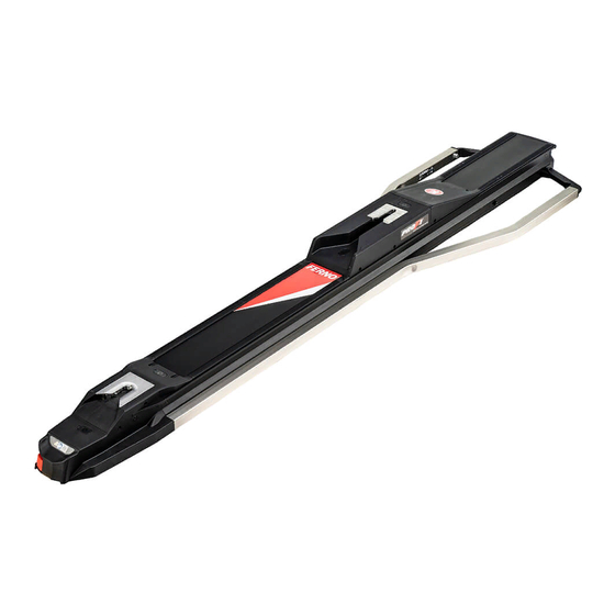
- Page 1 PRO F1 ™ Universal Fastening System Read this Manual and Retain for Future Reference Users’ Manual August 2018 Pub. No. 234-3691-00...
-
Page 2: Ferno Customer Relations
Limited Warranty Statement Queensland, Australia +617.3881.4999 The products sold by Ferno are covered by a limited warranty, which is printed on all Ferno invoices. The complete terms and conditions of the limited warranty, and the limitations of liability and disclaimers, are also available upon request by calling Ferno at 1.800.733.3766 or... -
Page 3: Table Of Contents
Notes __________________________________________________ 21 Compatible Products ______________________________ 13 General Specifications _____________________________ 14 Training Record__________________________________________ 22 Maintenance Record _____________________________________ 23 Components _____________________________________ 14 5 - Features _____________________________________________ 15 Nose-End Features ________________________________ 15 Fastening-Post Retainer ____________________________ 15 © Ferno-Washington, Inc. / August 2018 / 234-3691-00... -
Page 4: Safety Information
The symbols defined below are used on the fastening system and/or exceed all applicable guidelines before using the setup in in this’ manual. Ferno uses symbols recognized by the International an ambulance. Standards Organization (ISO), American National Standards Institute Improper installation can cause injury and damage. -
Page 5: Compliance
Contact Information When properly installed and used with appropriate additional For information about AMD standards: Ferno products, the PRO F1™ fastening system meets or exceeds the Ambulance Manufacturer’s Division following global specifications and standards. Be aware: standards and National Truck Equipment Association specifications are updated periodically. -
Page 6: Installation Requirements
If the ambulance is involved in a traffic accident, inspect the “Inspecting“ section of the fastening system users’ manual. Replace fastening system. any damaged components. For additional information, refer to Ferno’s Accident Policy. See ”Ferno Customer Relations” on page 2. Bumper step requirements: ●... -
Page 7: Installation
Wipe off excess threadlocker. Allow the Loctite threadlocker to dry for a minimum of one hour Rear of Ambulance before use. 3.75" (95 mm) 3.75" (95 mm) Sloped Sill Square Sill © Ferno-Washington, Inc. / August 2018 / 234-3691-00... -
Page 8: Positioning The Inserts
This is the only area where the long inserts can be placed into the floor plate. 25” (635 mm) 10” (254 mm) USA Minimum USA Minimum Rear Doors Seat © Ferno-Washington, Inc. / August 2018 / 234-3691-00... - Page 9 Fastening System to the Ambulance Floor” on page 10. Loctite® 242 - 2x 17. Allow the Loctite threadlocker to dry for a minimum of one hour before use. Screw (2) Washer (2) Floor Plate Insert Extender Insert © Ferno-Washington, Inc. / August 2018 / 234-3691-00...
-
Page 10: Attaching The Fastening System To The Ambulance Floor
Verify the fastening system is properly seated on the floor plate plate. and floor without obstructions. Alignment Hole Locator Post Placing the Fastener on the Locator Posts Locator Post ICS Charging Wire Floor Plate Locator Post © Ferno-Washington, Inc. / August 2018 / 234-3691-00... - Page 11 Figure 11. Do not tighten until all four mounting screws are threaded. Completely tighten the four mounting screws in the order shown in Figure 11. Verify the fastener is still properly seated on the floor. Close the four mounting screw access covers. © Ferno-Washington, Inc. / August 2018 / 234-3691-00...
-
Page 12: Operator Focus
INTERACTIVE CONTENT: For training videos and proper use of the ● PRO F1, scan a QR code in this manual, click a link in an electronic version of this manual or visit our website at www.ferno.com. NOSE: The nose is located at the end of the fastening system ●... -
Page 13: Overview
4 - OVERVIEW 4.1 Description WARNING The Ferno PRO F1™ Fastening System is a device designed to secure ® Improper use can cause injury. Use the fastening system a manufacturer-approved ambulance cot inside a ground-based only for the purpose described in this manual. -
Page 14: General Specifications
19” 471 mm before rounding the Imperial measurement. (C) Height 6” 151 mm Ferno reserves the right to change specifications without notice. For Weight 60.8 lb 27.6 kg more information, contact Ferno Customer Relations or your Ferno Construction Aluminum, Steel, Plastic distributor (page 2). -
Page 15: Features
INTEGRATED CHARGING SYSTEM (ICS®, OPTIONAL) If equipped, the Ferno® Integrated Charging System (ICS®) is located near the nose of the fastening system (Figure 13). When a Ferno® POWER X1 cot is locked in the fastening system and the ICS is connected and... -
Page 16: Using The Fastening System
6.3 Using the Fastening System Note: Refer to the cot users' manual for specific loading and unloading instructions. For additional manuals, contact Ferno. See “Ferno Customer Relations” on page 2. Always fully engage the yellow safety hook with the cot safety bar (Figure 15). -
Page 17: Maintenance
Wipe all surfaces with disinfectant. Follow the disinfectant manufacturer’s instructions for application method and contact time. Disinfectants and cleaners containing bleach, phenolics, or Ferno recommends you inspect the fastening system for damage as iodines can cause damage. Do not use products containing you disinfect. -
Page 18: Lubrication-Free Product
DO NOT: Spray water into the ICS port. ● Set the nozzle pressure at or below 3000 psi (20,684 kPa). Ferno recommends you use a nozzle with a wide angle of spray (25° or 40°). Keep the nozzle at least 18 inches (457 mm) away from the fastening system at all times. -
Page 19: Removing The Fastening System From The Floor For Cleaning
To prevent damage to the ICS charging wire, monitor the position of the wire as you lift the fastener off the floor plate. Mounting Screw Mounting Screw Location ICS Charging Wire Floor Plate © Ferno-Washington, Inc. / August 2018 / 234-3691-00... -
Page 20: Parts And Service, Accessories
+617.3881.4999 +617.3881.1125 Internet http://www.ferno.com.au/ 8.3 United Kingdom/EU Representative In the European Union or in the United Kingdom, contact Ferno to order parts or for professional repairs. Ferno (UK) Limited Stubs Beck Lane, Cleckheaton West Yorkshire BD19 4TZ, England, United Kingdom Telephone +44 (0) 1274.851999... -
Page 21: Notes
NOTES © Ferno-Washington, Inc. / August 2018 / 234-3691-00... -
Page 22: Training Record
Training Record TRAINING RECORD Training Method Trainer Date Printed Name Signature Read Video/ Initials Hands-On Manual Online © Ferno-Washington, Inc. / August 2018 / 234-3691-00... -
Page 23: Maintenance Record
Maintenance Record MAINTENANCE RECORD Date Maintenance Performed © Ferno-Washington, Inc. / August 2018 / 234-3691-00... - Page 24 Aviation 70 Weil Way Wilmington, OH 45177 Military Mortuary Rescue © Ferno-Washington, Inc. | 234-3691-00 | August 2018...
Need help?
Do you have a question about the PRO F1 and is the answer not in the manual?
Questions and answers