Advertisement
Quick Links
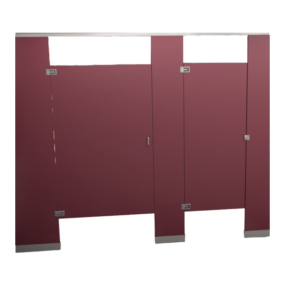
For Standard Height
Doors and Panels Only
Read this installation manual completely to ensure proper installation, then file it with the owner
or maintenance department. This installation manual provides instruction for the assembly of
Installation
normal partition configurations and standard components. Non-standard configurations or
components including but not limited to curved or angled walls, partial walls, oversized panels,
or modified hardware are not covered in this manual. Compliance and conformity to local codes
and ordinances is the responsibility of the installer.
Separate parts from packaging and make sure all parts are accounted for before discarding
packaging material. If any parts are missing, do not begin installation until you obtain the missing
Packing List
•
•
•
parts. To prevent warping, always lay the material flat. Do not lean the material against the wall or
IS
T H
E
•
S ID
U P
stack unevenly.
Before beginning installation, make sure that the wall and floor backing are adequate to support
the secure mounting of the toilet compartment units.
To minimize break-out, always use a support block when drilling through plastic laminate material.
Use caution when drilling. Accuracy is important!
Product warranties and parts information may be found on Bradley's web site at bradleycorp.com.
*HDWL-INSTR-001*
HDWL-INSTR-001 Rev. D; ECN 12-14-004J
© 2012 Bradley
Page 1 of 16
12/13/2012
Installation
Plastic Laminate Restroom Partitions
Floor-Mounted with Overhead Brace
Series 400
Table of Contents
Pre-Installation Information . . . . . . . . . . . . . . . . . . . . 2
Layout Dimensions for Brackets . . . . . . . . . . . . . . . . 3
Mounting Brackets to Wall . . . . . . . . . . . . . . . . . . . . . 4
Leveling Bolts to Pilaster . . . . . . . . . . . . . . . . . . . . . . 5
Mounting Brackets to Pilasters . . . . . . . . . . . . . . . 5-6
Pilaster Shoes . . . . . . . . . . . . . . . . . . . . . . . . . . . . . . 6
Panels and Pilasters . . . . . . . . . . . . . . . . . . . . . . . 7-8
Headrail . . . . . . . . . . . . . . . . . . . . . . . . . . . . . . . . . . . 9
Hinges . . . . . . . . . . . . . . . . . . . . . . . . . . . . . . . . 10-12
Latch and Strike/Keeper . . . . . . . . . . . . . . . . . . 13-14
Urinal Screens . . . . . . . . . . . . . . . . . . . . . . . . . . 15-16
IMPORTANT
P.O. Box 309, Menomonee Falls, WI USA 53052-0309
PHONE 800.BRADLEY (800.272.3539) FAX 262.251.5817
bradleycorp.com
Advertisement

Subscribe to Our Youtube Channel
Related Manuals for Bradley 400 Series


Summary of Contents for Bradley 400 Series
-
Page 1: Table Of Contents
To minimize break-out, always use a support block when drilling through plastic laminate material. Use caution when drilling. Accuracy is important! Product warranties and parts information may be found on Bradley's web site at bradleycorp.com. *HDWL-INSTR-001* HDWL-INSTR-001 Rev. D; ECN 12-14-004J P.O. - Page 2 36" (1537mm) (914mm) wall to center to centerline center 1" (25mm) 61¼" (1556mm) to face ½" 20½" (13mm) HR120 3" (76mm) 36" 24" 24" 10" (914mm) (610mm) (610mm) (254mm) 1" (25mm) gap Bradley • HDWL-INSTR-001 Rev. D; ECN 12-14-004J 12/13/2012...
- Page 3 Panel centerline: Measure the stall width across the back wall and place a mark at the base of the rear wall "A1" (“B”). Repeat this step for each panel, starting each measurement from the last panel centerline (“B1”). Bradley • HDWL-INSTR-001 Rev. D; ECN 12-14-004J 12/13/2012...
- Page 4 Remove the bracket pilaster/panel plumb line. and drill a Ø ⁵⁄₁₆ " hole (min. 2" [51mm] deep) Two-Eared at each hole location. Bracket One-Eared Bracket Bradley • HDWL-INSTR-001 Rev. D; ECN 12-14-004J 12/13/2012...
-
Page 5: Leveling Bolts To Pilaster
(chrome plated) barrel nuts and to the panels pilasters using the #14 x ⁵⁄₈ " with the #10-24 x ¾" (chrome plated) shoulder screws provided. screws and #10-24 x ¾" (chrome plated) barrel nuts provided. Secure the Brackets Bradley • HDWL-INSTR-001 Rev. D; ECN 12-14-004J 12/13/2012... -
Page 6: Pilaster Shoes
Plastic Anchor Drill Ø ⁵⁄₁₆" holes (min 2" [51mm] deep) in the floor and make sure the holes are free of dirt and debris. Bradley • HDWL-INSTR-001 Rev. D; ECN 12-14-004J 12/13/2012... -
Page 7: Panels And Pilasters
Secure the shoe Secure the shoe to the pilaster with the ¼-14 x ⁵⁄₈" to the pilaster with the ¼-14 x ⁵⁄₈" fasteners provided. fasteners provided. Bradley • HDWL-INSTR-001 Rev. D; ECN 12-14-004J 12/13/2012... - Page 8 Secure the shoe to Secure the shoe to the pilaster with the ¼-14 x ⁵⁄₈" the pilaster with the ¼-14 x ⁵⁄₈" fasteners provided. fasteners provided. Bradley • HDWL-INSTR-001 Rev. D; ECN 12-14-004J 12/13/2012...
-
Page 9: Headrail
(see view below). The headrail should be level with any adjacent headrail and should be located directly over the panel. Position each headrail onto the brackets and secure with required fasteners. Install the headrail end cap. Bradley • HDWL-INSTR-001 Rev. D; ECN 12-14-004J 12/13/2012... - Page 10 "B" "B" "B" Dim. "A" Dim. "B" Floor Mounted 13¼" 66⁵⁄₃₂" Overhead (337mm) (1680mm) Braced Wall Hung 13¼" 66⁵⁄₃₂" 69⁷⁄₃₂" (337mm) (1680mm) (1758mm) Wall Hung 1¾" 53²¹⁄₃₂ 58" (34mm) (1388mm) (1473mm) Bradley • HDWL-INSTR-001 Rev. D; ECN 12-14-004J 12/13/2012...
- Page 11 Bottom Botttom cam can be set in Finished View of Hinge different positions (-30°, -15°, 0°, 15°, and 30°) by sliding cam rib into the different bracket grooves Pilaster portion of hinge Bradley • HDWL-INSTR-001 Rev. D; ECN 12-14-004J 12/13/2012...
- Page 12 Standard pilaster. Secure with the fasteners provided. gap is ⁹⁄₃₂" (7mm). Spacer 12" (305mm) above finished floor Bradley • HDWL-INSTR-001 Rev. D; ECN 12-14-004J 12/13/2012...
- Page 13 #10 x ⁵⁄₈" screws provided. 3" Using the flat strike/keeper as (76mm) a template drill two Ø ¹⁄₈" pilot holes ¾" (19mm) deep. Secure the inswing flat strike/keeper with the #10 x ¾" screws provided. Bradley • HDWL-INSTR-001 Rev. D; ECN 12-14-004J 12/13/2012...
-
Page 14: Latch And Strike/Keeper
Secure the outswing flat shown. Drill two Ø ⁵⁄₃₂" pilot holes ⁵⁄₈" strike/keeper with the (16mm) deep. Secure the coat hook #10 x ¾" screws provided. with the #14 x ⁵⁄₈" screws provided. 36" (914mm) Bradley • HDWL-INSTR-001 Rev. D; ECN 12-14-004J 12/13/2012... - Page 15 15" (381mm) for 42" (1067mm) screens or 24" (610mm) for 42" (1067mm) screens or 18" (457mm) for 48" (1219mm) screens 18" (457mm) for 48" (1219mm) screens 24" (610mm) for 48" (1219mm) screens Bradley • HDWL-INSTR-001 Rev. D; ECN 12-14-004J 12/13/2012...
-
Page 16: Urinal Screens
Secure the screen to the continuous bracket at bracket with #10-24 x ¾" (stainless) barrel the established level line. nuts and #10-24 x ¾" (stainless) shoulder Center the bracket opening screws provided. on the plumb line. Bradley • HDWL-INSTR-001 Rev. D; ECN 12-14-004J 12/13/2012...
Need help?
Do you have a question about the 400 Series and is the answer not in the manual?
Questions and answers