
Related Manuals for Newcon Optik LRM 2200SI


Summary of Contents for Newcon Optik LRM 2200SI
- Page 1 Operation Manual LRM 2200SI LASER RANGE FINDER MONOCULAR 105 Sparks Ave., Toronto, ON M2H 2S5, Canada...
- Page 3 IMPORTANT INFORMATION Read prior to activation You have just purchased a sophisticated electro-optical device that emits invisible laser radiation. To operate it properly, please, read this manual carefully. NEVER direct laser beam at the eyes of people or animals ...
- Page 4 Caution - use of optical instruments such as binoculars, loupes, mirrors, lenses, etc. with this product increases eye hazard Avoid eye exposure to direct laser beam or its close reflection Prevent bright light from focusing through the eyepiece...
-
Page 5: Table Of Contents
TABLE OF CONTENTS BRIEF DESCRIPTION ..........2 Principle of operation ............2 Key Features ................ 3 DEVICE APPEARANCE .......... 4 DELIVERY SET ............6 Standard delivery set ............6 SPECIFICATIONS ............ 7 ... -
Page 6: Brief Description
FAILURE TO OBEY THE INSTRUCTIONS WILL VOID THE WARRANTY AND MAY CAUSE INJURY! 1. BRIEF DESCRIPTION LRM 2200SI Laser Rangefinder Monocular (the unit) is an advanced laser range finder system that enables instant distance, direction, elevation, azimuth and speed measurement. -
Page 7: Key Features
measurement allows height calculation. The unit measures azimuth simultaneously as well. Speed of an object moving closer or further from the unit can also be calculated using the time-of-flight principle. Key Features Three channel optical solution (optical, laser and receiver) ensures measurement accuracy ... -
Page 8: Device Appearance
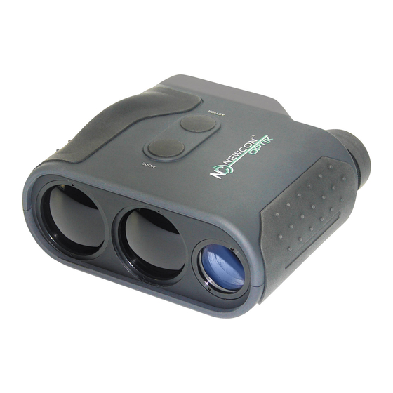
2. DEVICE APPEARANCE Fig. 1. Front view 1 - Eyepiece 2 - Objective lens 3 - Laser emitter lens 4 - Receiver lens 5 - M (Mode) button 6 - A (Action) button 7 - Body of the device 8 - Rubber grip... - Page 9 Fig.2. Rear view 1 - Eyepiece 10 - Tripod socket 9 - Battery compartment cover 12 - Classification 11 - Identification imprint imprint, shown below...
-
Page 10: Delivery Set
3. DELIVERY SET Standard delivery set LRM 2200SI is supplied in a set comprised of the following: LRM 2200SI 9V Lithium (non-magnetic) battery Soft carrying case Cleaning cloth Neck strap Operation manual Warranty card... -
Page 11: Specifications
4. SPECIFICATIONS Optics Magnification Objective lens diameter 25 mm Exit pupil diameter 3.6 mm Field of view 8 Type of coating Fully multi-coated optics Range Finder Laser Class 1, eye safe, 905 nm Measuring range 10 m – 2,200 m ... - Page 12 Inclinometer Measuring elevation range ±80 Accuracy ±1 Speed Detector Measured speed range 5-400 km/h Accuracy ±2 km/h Power Battery 9V Lithium (non-magnetic) Battery capacity Min 5,000 measurements (Scanning regime) 'Low Battery' indicator Environmental Operational temperature range -25 / +50 C (-13 / +122 Storage temperature range -45 / +65 C (-49 / +149...
-
Page 13: Operation Instructions
5. OPERATION INSTRUCTIONS Fig. 3. Liquid Crystal Display as seen through the eyepiece 1 – Low battery indicator -¦- 2 – Reticle (either or ) 3 – Units of measurement 4 – Measurement result 5 – Target quality indicator 6 – Laser active indicator 7 –... -
Page 14: Changing Battery
Changing battery To install a battery: Slide the battery compartment cover down (Fig. 2) Install the battery, observing correct polarity Do not force the battery while placing back inside the compartment. Close the compartment cover If the battery does not fit the compartment easily, it means that either polarity was reversed or the battery contacts are jammed. -
Page 15: Measuring Procedure
Measuring procedure When the unit is powered off the LCD will appear blank. To activate the unit press and hold A button (Fig. 1) for half a second. The word ‘READY’ will appear on the display to indicate the unit is powered on. Pressing the A button (Fig. -
Page 16: Target Selection Logic
surface is more reflective than a rough one. Larger targets reflect better than small ones. Ranging a target perpendicular to the laser beam provides better results than the one positioned under a sharp angle to the beam. Weather conditions that influence air transparency (rain, fog, snow, mist) reduce maximum range. -
Page 17: Operation And Service Modes
Note: Even with target selection logic the unit may not always be able to range the desired target as its reflectivity may be too low to produce enough laser beam reflections for statistically reliable calculation. A warning will be displayed if the result is not statistically reliable. -
Page 18: Accuracy Correction
Distance from meters to yards Speed from km/h to mph rEc – allows data recall of the last 10 measurement results: CLr – Clears all measurements SEt – allows the user to select the following advanced options: FrSt – First Target Measurement LASt –... - Page 19 calibration similar to one conducted during production process. To perform the accuracy correction, select corr from the CAL menu. Perform correction according to required measurement parameters by pressing Action button, see table below: Active mode of Correction measurement Condition parameter (Std) Install unit at 1 meter Distance...
-
Page 20: Compass Calibration
Magnetic North (not True North). If the unit detects large installation errors (unit is not well levelled or not aimed to the North), then LCD will show result “444” and “99”, which means that correction was not performed due to incorrect setup. Compass calibration If the System was exposed to a strong magnetic field or was not in use for a long time, the compass accuracy may diminish. -
Page 21: Individual Measurement And Scanning Regimes
Minimal gating distance of 000 m will be initially set, further pressing M button will increase gating distance by 100 m up to 2,100 m. When the desired distance is reached – select it by pressing Action button. OVER 100M – indicates that gating is active To deactivate gating choose gating value zero or switch to the default mode. -
Page 22: Data Recall Mode
measured in the Scanning mode, though both will be quickly displayed, the second one may be difficult to register by eye. Nevertheless all data is recorded and may be recalled (see Data Recall mode for details.) Data Recall mode In Data Recall mode results of the last 10 measurements can be displayed. -
Page 23: Additional Display Information
Pressing A button at any moment within the list of recalled results brings the unit to Ready to Measure mode. Choosing cLr at the end of recalled data will erase the device memory. Additional display information Ready to Measure Additional indication is displayed in mode: Indicates that distance is displayed in yards or Y or M... -
Page 24: Best Measuring Technique
6. BEST MEASURING TECHNIQUE Laser range finder measures distance by catching laser beam reflected from the target. Everything that improves reflection increases the measurement reliability and maximum range. 1. Use tripod when ranging remote targets. The longer is the distance, the greater is the beam shift due to hand tremor. 2. -
Page 25: Storage And Maintenance
7. STORAGE AND MAINTENANCE The unit is a sophisticated precision optical instrument equipped with laser and electronics. Therefore, it should be handled with due care. Keep away from direct sunlight. Avoid impacts, jolts, dust, moisture, and sharp changes of temperature. -
Page 26: Troubleshooting
8. TROUBLESHOOTING The ranging does not work. The display is transparent. Check the charge of the battery. Replace it if it is weak. The ranging mode does not work. The display shows results of the last measurement or is transparent. Wait for 16 seconds, and press the Action button again. -
Page 27: Warranty
Postage, insurance, and shipping costs incurred while presenting your NEWCON product for warranty service are your responsibility. If shipping from North America please include a cheque or money order payable to NEWCON OPTIK for the amount of US$15.00 to cover handling and return shipping. - Page 28 9am-5pm, Monday - Friday, Eastern Standard Time. At no time should equipment be sent back to Newcon without following the instructions of our technical support department. NEWCON OPTIK accepts no responsibility for unauthorized returns. To locate NEWCON Authorized Dealer call: Tel: +1(416) 663-6963 Fax: (416) 663-9065 Email: newconsales@newcon-optik.com...
- Page 29 QUALITY CERTIFICATE The unit has passed the quality inspection. Production date Serial number Quality Inspector Purchase date...
- Page 32 NEWCON OPTIK Printed in Canada...
Need help?
Do you have a question about the LRM 2200SI and is the answer not in the manual?
Questions and answers