
Related Manuals for Eaton 2 Series


Summary of Contents for Eaton 2 Series
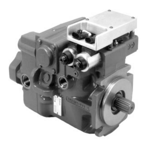
- Page 1 Eaton ® No. 6-636 August 1997 Heavy Duty Hydrostatic Pumps Parts & Repair Information Series 2 Hydrostatic Pumps...
-
Page 2: Table Of Contents
Table of Contents Introduction ................................3 Required Tools for Disassembly/Reassembly ......................3 Major Assemblies – Disassembly Order – ID Tag Information ................... 4 Exploded View Drawing – Charge Pump, End Cover .................. 5 Exploded View Drawing – Rotating Group ....................6 Exploded View Drawing –... -
Page 3: Introduction
Introduction This Manual provides service information for Eaton Heavy Series 2 Variable Displacement Pumps, Models 33, 39, 46, 54 and 64. Step by step instructions for complete disassembly, inspection and reassembly of the pump are given. The following recommendations should be followed to insure successful repairs. - Page 4 Serial No. C Identifies Specific Unit Configuration Rotation D Month of Manufacture NOTE: This is a typical Series 2 configuration Eaton Corporation E Year of Manufacture Hydraulics Division your model may differ slightly from this view Spencer, Iowa 51301 F Specific Serial Number of Unit depending on features installed.
- Page 5 Exploded View Drawing – Series 2 Variable Displacement Pump Detail of Charge Pump & Adaptor Pads are on Pages 15 & 16 NOTE: This is a typical Series 2 configuration your model may differ slightly from this view Model Number depending on features installed.
- Page 6 Exploded View Drawing B Items – Series 2 Variable Displacement Pump Because critical calibrations have been made at the factory the Servo Assembly should not be disassembled. NOTE: This is a typical Series 2 configuration your model may differ slightly from this view depending on features installed.
- Page 7 Exploded View Drawing – Series 2 Variable Displacement Pump Control Valve (Refer to pages 17-23 for Valve Options) Control Valve Gasket ID Tag Refer to Optional Page 4 for details Optional Plug Optional Magnetic Speed Sensor C Items...
-
Page 8: Parts List
Parts List – Series 2 Variable Displacement Pump Item Part No. Qty. Description ♦ Main Housing (see parts list on page 11) ♦ Drive Shaft Sub-Assembly (see parts list on page 12) ♦ End Cover (see parts list on page 16) 103090-325 Hex Bolt HD 3/8-16 Gr8 (54,4 - 63,7 - 75,4 cm /rev) - Page 9 Parts List – Series 2 Variable Displacement Pump Item Part No. Qty. Description ◊ 41 A Bearing Shim (54,4 - 63,7 - 75,4 cm /rev) (see Shim kit 990715-000 page 26) ◊ Bearing Shim (89,2 - 105,5 cm /rev) (see Shim kit 990388-000 page 26) 42A43A 108295-000 Bearing Cup/ Bearing Cone S/A (54,4 - 63,7 - 75,4 cm /rev)
- Page 10 Parts List – Series 2 Variable Displacement Pump Item Part No. Qty. Description ◊ 87 C O-Ring (see gasket kit 990710-000 page 27) ◊ 95 A Charge Pump Adaptor Kits see page 14-15) ◊ 116 C Drive Shaft Seal (see Shaft Seal Kit page 26) ◊...
-
Page 11: Main Housing
Parts List – Series 2 Variable Displacement Pump Item 1 C Main Housing Item Part No. Qty. Description 109747 Main Housing – 54,4 - 63,7 - 75,4 cm /rev 109745 Main Housing – 54,4 - 63,7 - 75,4 cm /rev – with IPOR 109746 Main Housing –... -
Page 12: Propel Valve Plate Or V-Groove Plate
Parts List – Series 2 Variable Displacement Pump Item 13 A Propel Valve Plate or V-Groove Plate CW V-Groove Plate CW Propel Valve Plate Plate, Propel Valve or Plate, V-Groove Part Number Part Number Part Number Part Number Model 33, 39 Model 46 Model 54 Model 64... -
Page 13: Rotating/Swash Plate Assembly
Parts List – Series 2 Variable Displacement Pump Standard Slipper Wide Land Slipper Item 12 B (from page 6) Rotating/Swash Plate Assembly 12-B 12-A 12-2 12-3 12-4 12-5 12-6 12-7 12-8 12-9 12-10 12-11 12-12 Note: The Bearing Plate is item 14 on page 6 12-13 and is listed on Pages 8 and 12. -
Page 14: Charge Pump Kit Assemblies
Parts List – Series 2 Variable Displacement Pump Item 15 A Charge Pump Kit Assemblies 15-3 15-4 15-5 15-1 15-6 15-7 15-8 15-2 15-9 15-10 A-Pad 15-A A-pad, High Torque Charge Pump, Dual 2 Bolt Mount, 15-C No Shaft Seal, 9 Tooth 16/32 Pitch Spline 15-D 15-B (Available For All Models) - Page 15 Item 15 A Charge Pump Kit Assemblies – – – – – – – – – – – – – – – – – ◊ ◊ ◊ ◊ ◊ – – – ◊ ◊ ◊ ◊ ◊ – – – ◊...
-
Page 16: End Covers
Parts List – Series 2 Variable Displacement Pump Item 3 A End Covers* Item Part No. Qty. Displacement Main Ports POR Options 110718 54,4 & 63,7 cm /rev Remote Filter Ports 110568 54,4 & 63,7 cm /rev 110619 54,4 & 63,7 cm /rev 110300 54,4 &... -
Page 17: Control Valves
Parts List – Series 2 Control Valve Assemblies Item 6 C Control Valves 990704-000 – Manual Control Valve (Kit) Item Part No. Qty. Description 990704-000 Manual Control Valve (Kit) includes below; 110038-001 Manual Control Valve S/A 108992-000 Control Gasket 95912-088 Cap Screw SOC HD 5/16-18 GR 8 95912-150 Cap Screw SOC HD 5/16-18 GR 8... -
Page 18: Manual Control Valve With N/C Neutral Lockout & Potentiometer (Kit)
Parts List – Series 2 Control Valve Assemblies 990706-000 – Manual Control Valve with N/C Neutral Lockout & Potentiometer (Kit) 990764-000 – Neutral Lockout Switch Mating Connector Kit* Connector (1) – Cross Reference Delphi/Packard P/N 1201 5792 Terminal (2) – Cross Reference Delphi/Packard P/N 1208 9040 Cable Seal (2) –... -
Page 19: Manual Control Valve With N/C Neutral Lockout (Kit)
Parts List – Series 2 Control Valve Assemblies 990705-000 – Manual Control Valve with N/C Neutral Lockout (Kit) Item Part No. Qty. Description 990705-000 Manual Control Valve with N/C Neutral Lockout (Kit) includes below; 110039-000 Manual Control Valve with N/C Neutral Lockout 108992-000 Control Gasket 95912-088... -
Page 20: Manual Control Valve With Potentiometer (Kit)
Parts List – Series 2 Control Valve Assemblies 990707-000 – Manual Control Valve with Potentiometer (Kit) 990763-000 – Potentiometer Mating Connector Kit* Connector (1) – Cross Reference Delphi/Packard P/N 1201 0717 Terminal (3) – Cross Reference Delphi/Packard P/N 1208 9040 Cable Seal (3) –... - Page 21 Parts List – Series 2 Control Valve Assemblies Solenoid Control Valve Assemblies & Mating Connector (Kits) 990765-000 Solenoid Control Mating Connector Kit* 0 – h t i o i t ) t i Solenoid Mating Connector Kit Connector (1) – Cross Reference Delphi/Packard P/N 1212 4583 h t i 0 –...
-
Page 22: (Ep) Electronic Proportional Displacement Control (Kit)
Parts List – Series 2 Control Valve Assemblies (EP) Electronic Proportional Dispalacement Control (Kits) 990762-000 – EP Control Mating Connector Kit* Command Input Signal Mating Connector Connector (1) – Cross Reference Delphi/Packard P/N 1211 0293 Terminal (3) – Cross Reference Delphi/Packard P/N 1204 8074 Cable Seal (3) –... - Page 23 Parts List – Series 2 Control Valve Assemblies EP Control Solenoid Actuated Valve Assemblies (Kits) 990767-000 – EP Solenoid Mating Connector Kit* EP Solenoid Mating Connector Kit Connector (1) – Cross Reference Delphi/Packard P/N 1204 7950 Terminal (4) – Cross Reference Delphi/Packard P/N 1204 8074 Cable Seal (4) –...
- Page 24 Parts List – Series 2 Control Valve Assemblies (MUX) Multiplex Displacement Control 990768-000 – MUX Mating Connector Kit* MUX Mating Connector Connector** (1) – Cross Reference Delphi/Packard P/N 1203 4163 Terminal.(8) – Cross Reference Delphi/Packard P/N 1210 3881 Cable Seal Plug (6) – Cross Reference Delphi/Packard P/N 1203 4413 Recomended wire size: 16 - 18 AWG Recomended cable diameter: 2.03 - 2.40 mm Alternate reference source: Pioneer Standard Electronics 1-800-257-6613...
-
Page 25: Low Pressure Relief Valve Kit
Parts List – Series 2 Kits 990713-000 Low Pressure Relief Valve Kit Item Part No. Qty. Description 48 C 9900713-000 LPRV Plug S/A Includes Below: – 48-1 109077-00 LPRV Plug 48-2 8785-012 O-Ring – 48-3 108870-002 LPRV Spring – 48-4 108869-000 LPRV Poppet 48-5... - Page 26 Parts List – Series 2 Kits 990710-000 Repair Gasket Kit Item Part No. Qty. Description 108480-000 End Cover Gasket (54,4 - 63,7 - 75,3) 108974-000 End Cover Gasket (89,2 - 105,5) 15-2 A 103223-000 Sealing Washer 15-4 A 8761-156 O-Ring (charge Cover) 15-4 A 8761-157 O-Ring (charge Cover) 27 C...
- Page 27 – Series 2 Variable Displacement Pump The following repair information may be used in the inspection, Next remove the control valve conversion and repair of the Eaton Series 2 Variable Displace- assembly gasket and discard. ment Pump. The Pump Shown in this section incorporates the...
- Page 28 Repair Information – Series 2 Variable Displacement Pump Shown here are all the parts used Next using a 9/16 hex key in the internal pressure override. or allen wrench remove Valve plug, shims spring end and the two high pressure re- valve poppet.
- Page 29 Repair Information – Series 2 Variable Displacement Pump Using a 1/4 bit socket or With the gerotor outer ring re- Figure 19 hex key, remove the charge moved from the eccentric ring, pump cover retaining cap remove the eccentric ring. The screws.
- Page 30 You can use the same ing. Only units with the size and type of puller that was optional Internal Pressure used on the EATON Series 0 or Override option incorpo- ball guide transmissions. (see rated the additional O-rings Figure 37) NOTE: IF you do...
- Page 31 Repair Information – Series 2 Variable Displacement Pump Reposition the swashplate and Shown here is a simple rotating group back on the sup- wooden box that may be port base. Next, using a 1/4 in. used to support the rotat- Figure 44 allen wrench or bit socket, re- ing group during disas-...
- Page 32 Repair Information – Series 2 Variable Displacement Pump Next, remove the two Next, using a 3/4 in. end wrench, Figure 49 swashplate bearings and remove the servo adjustment clocking links. (see Fig- screw lock nut and special bev- ure 49) eled washer from the adjustable side servo piston cover.
- Page 33 Repair Information – Series 2 Variable Displacement Pump Install the servo piston cover Complete Reassembly on the servo piston adjustment screw. Install about half way Before reassembly, clean all parts and assemblies. Inspect and down the adjustment screw. replace damaged parts and assemblies. When reworking parts, Next, install a new threaded do not use course grit paper, files or grinders on finished sur- seal and special washer.
- Page 34 Repair Information – Series 2 Variable Displacement Pump Lubricate and reassemble the Lubricate and install the Figure 73 rotating group. (see Figure 73) two bearing races into the Figure 70 pump housing. Install the races on their locating pins with the grooved side of the races towards the center of the pump hous- ing.
-
Page 35: Hold Down (Kits)
Repair Information – Series 2 Variable Displacement Pump Lubricate and install the VERY CAREFULLY pick up the Figure 83 Figure 78 input shaft into the rotat- entire assembly and install it ing group and swashplate into the pump housing. Install assembly. - Page 36 Repair Information – Series 2 Variable Displacement Pump The next step in zeroing in Aligning the pump end cover Figure 88 Figure 93 the swashplate is to use a with the hold down arm assem- 3/8 in. end wrench to turn bly alignment tool (2) dowels, the servo piston adjust- install the end cover.
- Page 37 Repair Information – Series 2 Variable Displacement Pump Again, use the two hold down Install a magnetic base in- Figure 103 Figure 98 arm assembly alignment tool dicator on the mounting and dowels on the pump hous- flange with the indicators ing.
- Page 38 Repair Information – Series 2 Variable Displacement Pump Lightly coat the charge Install the dowel pin in the end Figure 108 Figure 113 pump drive key with pe- cover. Lightly coat the end cover troleum jelly to help hold side of the valve plate with pe- it in position during as- troleum Jelly (Vaseline) for re- sembly.
- Page 39 Repair Information – Series 2 Variable Displacement Pump Lubricate and install the Next, install the high pressure seal ring on the auxiliary valves or check valve assem- pump mounting flange. blies. Torque to 120 ft. lbs. (see Figure 118) [162,7 Nm] to 130 ft. lbs. [176,2 Nm] (see Figure 23) Figure 123 Figure 118...
- Page 40 Repair Information – Series 2 Variable Displacement Pump Next, install the spacer Lubricate and install the washer on top of the seal. control feedback assem- When severe wear in the bly on the swashplate as- seal area of the pump shaft sembly.
-
Page 41: Troubleshooting
Troubleshooting – Series 2 Variable Displacement Pump This section provides the information necessary to troubleshoot a typical hydrostatic system using an Eaton Series 2 hydrostatic pump. Using this section will help you to diagnose any minor problems that may occur. - Page 42 Troubleshooting – Series 2 Displacement Variable Pump Valve and Test Port Locations Manual Control Check Valve or Valve Optional Port A High Pressure Relief Valve System Pressure Test Port For Port A Charge Pressure Test Port System Pressure Test Port For Port B Check Valve or Optional Port B...
-
Page 43: Gauge Requirements, Gauge Port Size And Location
Troubleshooting – Series 2 Variable Displacement Pump Gauge Requirements, Gauge Port Size and Locations System Pressure Gauges ( 2 ) 0 - 10,000 PSI [ 0 - 610 bar ] Inlet Vacuum Gauge - 30 to + 30 inHg (Mercury) Charge Pressure Gauge [ -1 to + 2 bar ] 0 - 600 PSI [ 0 - 37 bar ]... -
Page 44: Pressure Readings
Troubleshooting – Series 2 Variable Displacement Pump Pressure Readings The pressures given in this manual are gauge pressures or delta pressures. A pressure gauge reads zero when connected to atmospheric pressure. Any reading above or below this zero point is referred to as gauge pressure (PSI). Delta pressure is the difference of two gauge pressures in a hydraulic circuit. -
Page 45: Fault-Logic Troubleshooting
Troubleshooting – Series 2 Variable Displacement Pump Fault-Logic Trouble Shooting This Fault-Logic Trouble Shooting Guide Explanatory Diagram is designed as a diagnostic aid in locating possible transmission problems by the user. Symptom: Match the transmission symptoms with the Action problem statements and follow the action Step steps shown in the box diagrams. - Page 46 Transmission Operates in One Direction Only Inspect External Inspect Inspect Pump Control System Relief Pump Control Linkage (if Used) Valves Valve Defective Defective Defective Repair Repair Repair Replace Replace Replace Inspect Inspect Replace Shuttle Charge Pump Valve Check Valves 6 Defective Defective Repair...
- Page 47 System Operating Hot Check Oil Inspect Inspect Heat Check Level in Heat Exchanger By-Pass Charge Reservoir Exchanger Valve (if Used) Pressure Clogged Below Level Defective Low in Low in Fill to Repair Neutral,Forward Proper Clean Forward Level Replace Reverse Reverse Inspect Inspect Inspect Charge...
- Page 48 System Response Sluggish Replace Check Inspect System Inspect Transmission Charge By-Pass Valve Pump Control (if Used) (Pump & Motor) Pressure Valve Defective Defective Repair Repair Replace Replace Low in Low in Forward Neutral,Forward Neutral Reverse Reverse Inspect Inspect Charge Inspect Charge Inspect Charge Inspect Relief Valve...
- Page 49 System Will Not Operate in Either Direction Check Oil Inspect External Inspect Motor Check Level in Pump Control By-Pass Valve Charge Reservoir Linkage (if Used) (if Used) Pressure Defective Below Level Defective Low in Fill to Repair Repair Low in Proper Neutral,Forward Forward...
- Page 50 Troubleshooting – Series 2 Variable Displacement Pump Inspect External Pump Control G. Defective Potentiometer Linkage for: H. Misadjusted speed sensor (on motor when used) Manual Operated Controls I. Defective speed sensor Misadjusted or disconnected J. Defective electronics module Binding, bend or broken Hydraulic Remote Controls Inspect Servo Piston for: Improper pilot pressure...
- Page 51 Eaton to publish a fluid mainte- select the appropriate fluids for use in systems that nance schedule that would cover every situation. Field employ Eaton hydrostatic components.
- Page 52 • Contact your Eaton representative if you have specific questions about the fluid requirements of Eaton hydrostatic • If the natural color of the fluid has become black it is components.
-
Page 53: Special Tools
Special Tools – Series 2 Variable Displacement Pump 4.75 .040 X 45¡ BOTH ENDS FOUR REQ'D. 1.500 MAT'L: DRILL ROD .060 X 45¡ 1.013–.005 .307–.001 .250 .519 .785–.005 .211–.005 .25R 1.731 –.005 2.231 3.462–.001 3.731 6.000 3.641 –.005 .25R .437–.005 R 1.247–.005 MAT'L 1.875... - Page 54 Special Tools – Series 2 Variable Displacement Pump Main Shaft Bearing Stop Limit Tool It is recommended that replacement shafts be purchased as an assembly with the bearing already pressed ± into place. In the event a bearing is replaced in the field it must be ±...
- Page 55 21 ....21 Tooth 16/32 Pitch Spline F ....345 bar [5000 lbf/in 23 ....23 Tooth 16/32 Pitch Spline G ....380 bar [5500 lbf/in † Ask your Eaton representative for additional shaft options M ....395 bar [5725 lbf/in Position 9 Input Rotation H ....
- Page 56 C ....24 bar [348 lbf/in M ....2,59 [.102] Diameter D ....25,5 bar [369.8 lbf/in * Eaton recommends you chose an orifice for control orifice supply (P). The servo orifice (S ) and the servo orifice (S E ....27 bar [391.5 lbf/in are optional, except when specifying a pressure override.
- Page 57 Eden Prairie, MN 55344 Scotland, KY7 4NW 40880 Ratingen, Germany in an ISO-9001-certified site. Telephone 612/937-9800 Telephone 01-592-771-771 Telephone 02102-406-830 Fax 612/937-7130 Fax 01-592-773-184 Fax 02102-406-800 www.eaton.com Copyright Eaton Corporation, 1997 Form No. 6-636 All Rights Reserved Printed in USA...
Need help?
Do you have a question about the 2 Series and is the answer not in the manual?
Questions and answers