
Subscribe to Our Youtube Channel
Related Manuals for MiTAC Master Series


Summary of Contents for MiTAC Master Series
- Page 1 MB1-10AP User Manual V1.4 aster Series Embedded System Intel® Apollo Lake Processors Efficient, Versatile, and Rugged & Reliable...
-
Page 2: Preface
MiTAC Corp., Ltd. All information and specification provided in this manual are for reference only and remain subject to change without prior notice. - Page 3 Safety Information WARNING! / AVERTISSEMENT! Always completely disconnect the power cord from your chassis whenever you work with the hardware. Do not make connections while the power is on. Sensitive electronic components can be damaged by sudden power surges. Only experienced electronics personnel should open the PC chassis.
- Page 4 Ordering Information Model Number Description MB1-10AP-N3350 Fanless embedded system with Intel® Apollo Lake N3350 processor. 1x204Pin DDR3L SO-DIMM 1857Mhz up to 8GB, 1xHDMI, 3xGbE LAN, 4xUSB3.0, 2xCOM, 8~24V DC-in, with wall mount, L6 system. Fanless embedded system with Intel® Apollo Lake N3350 MB1-10AP-N3350-POE processor.
- Page 5 Optional Xpansion Modules Model Number Description MS-01VGA-D10 Xpansion Module with VGA Port MS-01DVI-D10 Xpansion Module with DVI-D Port MS-01DPN-D10 Xpansion Module with DisplayPort MS-02COM-D10 Xpansion Module with 2 x RS232/422/485 (Non-isolation) Support 5V/12V Power Xpansion Module with 8-bit Isolated DIDO (4 x DI, 4 x DO) MS-08DIO-T10...
-
Page 6: Table Of Contents
CONTENTS PREFACE ............................... 2 CHAPTER 1: INTRODUCTION ........................ 8 1.1 Overview ..........................8 1.2 Product Features ........................8 1.3 Hardware Specification ......................9 1.4 Mechanical Specification ..................... 12 1.5 System I/O Placement ......................13 CHAPTER 2: DIP SWITCH SETTING AND PIN DEFINITION ..............16 2.1 DIP Switch and Connector Overall Placement .............. - Page 7 INTRODUCTION This chapter provides the MB1-10AP Embedded System product overview, including features, hardware and mechanical specifications.
-
Page 8: Chapter 1: Introduction
I/O placement. 1.1 Overview MiTAC’s MB1-10AP embedded system is the next generation embedded system with Intel® Apollo Lake embedded processor. The efficient performance, OCP/OVP power protection, and expandable design provide the solution for routine tasks and most types of application. -
Page 9: Hardware Specification
1.3 Hardware Specification SYSTEM ® Intel Apollo Lake-M N3350 / N4200 Processors ® Chipset Intel SoC Integrated System Memory DDR3L 1866 MHz / 1 x 204-pin SO-DIMM / Max. 8GB (Non-ECC) ® Graphics Intel HD Graphics Display Interface HDMI 1.4 / Optional DisplayPort / VGA / DVI-D by Xpansion Module Storage Slot 1 x 2.5 HDD / SSD (Default w/ HDD Bracket) 1 x mSATA... - Page 10 Operating -25°C to 70°C (For non-PoE SKU) Temperature -25°C to 60°C (For PoE SKU) with 0.7m/s Air Flow and Wide Temperature Memory/Storage Operating Humidity 10%~90% R/H (Non-condensing) Vibration Resistance Operating, 5 Grms, 5-500 Hz, 3 Axes (w/ SSD, according to IEC60068-2-64) Shock Resistance Operating, 50 Grms, Half-sine 11 ms Duration (w/ SSD, according to IEC60068-2-27)
- Page 11 *Note : The maximum ambient operating temperature is 40°C if the external AC adapter model: EA11011M or EA10681V will be placed in the same high temperature area with the embedded system. *Note : CAUTION - Lithium battery is included in this embedded system. Please do not puncture, mutilate, or dispose of battery in fire.
-
Page 12: Mechanical Specification
1.4 Mechanical Specification Mechanical Dimension: 170 mm x 105 mm x 57 mm... -
Page 13: System I/O Placement
1.5 System I/O Placement Front I/O: Rear I/O:... - Page 14 Xpansion Module (Optional) Configuration...
- Page 15 DIP SWITCH SETTING AND PIN DEFINITION This chapter provides information about how to set up the dip switch and use I/Os of MB1-10AP Embedded System hardware.
-
Page 16: Chapter 2: Dip Switch Setting And Pin Definition
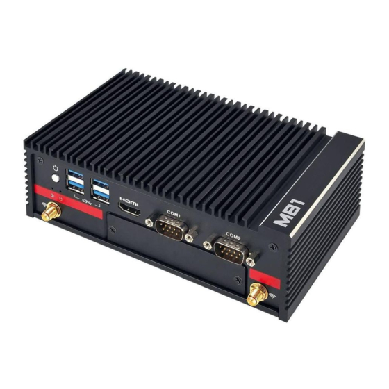
CHAPTER 2: DIP SWITCH SETTING AND PIN DEFINITION This chapter provides information about how to set up the dip switch, and use internal I/Os of MB1-10AP Embedded System hardware. 2.1 DIP Switch and Connector Overall Placement Front View: Power button Dual USB3.0 Dual USB3.0 HDMI... - Page 17 Mic-in Audio Jack RJ45 10/100/1G Dual RJ45 10/100/1G (Non PoE or PoE) 3-pin Terminal Block DC IN SW_CMOS1 Remote Power on/off Header Bottom View: J_WLAN1 J_MSATA1 J_DB1 J_SATA1 J_BAT1 AT/ATX Switch SW_PW2 SW_RI2 SW_RI1 SW_PW1 J_PW1 J_SIM_1 Buzzer...
-
Page 18: Dip Switch Setting
2.2 DIP Switch Setting Location #B6 Add this table in silkscreen TXT SW_ATX1 Default ATX mode Location #B7/B8/B9/B10... -
Page 19: Connector Pin Definition
2.3 Connector Pin Definition Indicator for Dual Intel i210-IT LAN Color State Condition Diagram LAN link is not established Link or LAN disable LAN link is established or Link Green LAN port disable Link Green blinking LAN activity occurring 10 M b/s data rate Speed or LAN disable... - Page 20 +12V +12V +12V SATAHDR_TXP0_C SATAHDR_TXN0_C SATAHDR_RXN0_C SATAHDR_RXP0_C 3-pin terminal block for DC Input Signal +8~24VIN DC IN...
- Page 21 2-pin Remote Power On/Off Header Signal Signal MB Side Connector: Molex 151064-0152 Suggestive Cable Side Plug: Molex 151100-0002 COM1 and COM2 on M/B MB COM1 and COM2 RS232, RS422, RS485 setting is at BIOS setup menu...
- Page 22 MS-02COM-D10 (Optional) Xpansion Module with 2 x RS232/422/485 (Non-isolation) Support 5V/12V DC Power Output Notes: Don't support Power HOT switch at SW_PW3 and SW_PW4 in Xpansion Module Below is Xpansion Module with COM3 and COM4: See the power RS232 setting as below table: Default setting is RI signal at A location from SW_RI3 and SW_RI4 Power COM setting with RI signal: Default setting...
- Page 23 Power 5V setting: SET at C location from SW_RI3 and SW_RI4 SET at A location from SW_PW3 and SW_PW4 Power 12V setting: SET at C location from SW_RI3 and SW_RI4 SET at C location from SW_PW3 and SW_PW4...
- Page 24 Power 12V setting: Change at C location from SW_RI3 and SW_RI4 and at C location from SW_PW3 and SW_PW4 MS-08DIO-T10 (Optional) Xpansion Module with 8-bit Optical Isolation DIDO (4 x DI, 4 x DO) V_ISO ISO_DO_0 ISO_DO_1 ISO_DO_2 ISO_DO_3 ISO_DI_0 ISO_DI_1 ISO_DI_2 ISO_DI_3 GND_ISO...
- Page 25 SYSTEM SETUP This chapter provides information about how to set up the MB1-10AP Embedded System hardware installation.
-
Page 26: Chapter 3: System Setup
CHAPTER 3: SYSTEM SETUP This chapter provides information about how to set up the MB1-10AP Embedded System hardware installation. Warning: The edge of MB1-10AP aluminum alloy fins is a little bit sharp. Please be careful when you move the unit, do the installation, and operate the embedded system! 3.1 2.5”... -
Page 27: Wifi Module Installation
Move HDD tray as arrow direction Lift HDD tray about 45 degrees and draw it out Install 2.5”HDD to the HDD tray 3.2 WiFi module Installation Use mPCIe extension bracket which is in accessories kit to fix half size mPCIe wifi module, and install to the full size mPCIe slot... -
Page 28: Dram Installation
3.3 DRAM Installation Loosen 4 screws from MB (2 screws from front & rear cover) Draw the MB sub-assembly out from top cover as arrow direction... - Page 29 Remove the film from top cover & install DIMM to MB...
- Page 30 BIOS SETUP This chapter provides information about how to set up BIOS and use BIOS menu items to adjust basic function settings.
-
Page 31: Chapter 4: Bios Setup
CHAPTER 4: BIOS SETUP This chapter provides information about how to set up BIOS and use BIOS menu items to adjust basic function settings. 4.1 Main Page... - Page 32 Field Name BIOS Vender Default Value AMI Megatrends Comment This field is not selectable. There is no help text associated with it. Field Name BIOS Version Default Value Display the version of the BIOS Comment This field is not selectable. There is no help text associated with it. Field Name Build Date Default Value...
-
Page 33: Advance Page
4.2 Advance Page BIOS Setup Name [Default] / Select Description Value LAN 1 Disabled / [Enabled] Enable/Disable LAN1 LAN 2 Disabled / [Enabled] Enable/Disable LAN2 LAN 3 Disabled / [Enabled] Enable/Disable LAN3 Restore AC Turn on / Turn off / Select AC power state when power is re-applied Power Loss [Last state]... - Page 34 the Internal Graphics Device. ► Intel(R) I210 Configure Gigabit Ethernet device parameters Gigabit Network Connection ► Trusted Select fTPM/dTPM Computing ► NCT6116D Super System Super IO Chip Parameters. IO Configuration ► Hardware Monitor hardware status Monitor ► S5 RTC Wake Enable system to wake from S5 using RTC alarm Setting ►...
- Page 35 4.2.1 Intel(R) I210 Gigabit Network Connection BIOS Setup Name [Default] / Select Value ► Intel(R) I210 Gigabit Network Conection ► NIC Configuration Link Speed [Auto] / 10 Mbps Half / 10 Mbps Full / 100 Mbps Half /100 Mbps Full Wake On LAN Enabled / [Disabled] ►...
- Page 36 BIOS Setup Name [Default] / Select Description Value Security Device Disabled / Enables or Disables BIOS support for security device. Support [Enabled] O.S. will not show Security Device. TCG EFI protocol and INT1A interface will not be available. 4.2.3 NCT6116D Super IO Configuration...
- Page 38 BIOS Setup Name [Default] / Select Value Description ► NCT6116D Super System Super IO Chip Parameters. IO Configuration Super IO Chip NCT6116D ► Serial Port 1 Set Parameters of Serial Port 1 Configuration (COMA) Serial Port [Enabled] / Disabled Enable or Disable Serial Port (COM) Device Settings IO=3F8h;...
- Page 39 Serial Port [Enabled] / Disabled Enable or Disable Serial Port (COM) Device Settings IO=2F8h; IRQ=3 Serial Port Mode 1T/1R RS-422 Select Serial Port Mode / [3T/5R RS-232] / 1T/1R RS-485 TX ENABLE Low Active / 1T/1R RS-422 with termination resister / 1T/1R RS-485 with termination resister TX ENABLE Low Active / Disable...
- Page 40 +12V + x.xxx V AVSB + x.xxx V CPUVCORE + x.xxx V VCC3V + x.xxx V VSB3V + x.xxx V VBAT + x.xxx V 4.2.5 S5 RTC Wake Setting BIOS Setup Name [Default] / Select Description Value Wake System from [Disabled] / Fixed Enabler or disable System wake on alarm event, Select Time...
- Page 41 4.2.6 CPU Configuration BIOS Setup Name [Default] / Select Description Value Intel Virtualization Disabled / When enabled, a VMM can utilize the additional Technology [Enabled] hardware capabilities provided by Vanderpool Technology Burst Frequency Disabled /[Enabled] Burst Frequencey...
-
Page 42: Security Page
4.3 Security Page Security Value Description Setup Administrator xxxx Set Administrator Password Password User Password xxxx Set User Password ► Secure Boot Secure Boot configuration ► BIOS Update BIOS Update support... - Page 43 4.3.1 Secure Boot Security Value Description Secure Boot Disabled / Secure Boot activated when: Secure Boot is enabled Platform [Enabled] Key(PK) is enrolled, System mode is User/Deployed, and CSM is disabled Secure Boot [Standard] / Secure Boot Mode - Custom & Standard, Set UEFI Secure Customization Customer Boot Mode to STANDARD mode or CUSTOM mode, this...
- Page 44 Boot variables root folder on a file system device Secure Boot variables | Size | Keys | Key Source ► Platform Key(PK) [Details] / Enroll Factory Defaults or load keys from a file formatted as: Export / 1.Public Key Certificate in: a)EFI_SIGNATURE_LIST, Update / b)EFI_CERT_X509 (DER encoded), c)EFI_CERT_RSA2048 Delete...
- Page 45 4.3.2 BIOS Update...
-
Page 46: Boot Page
4.4 Boot Page Security Value Description Boot Configuration Setup Prompt Number of seconds to wait for setup activation key. Timeout 65535(0xFFFF) means indefinite waiting. Bootup NumLock [On] / Off Select the keyboard NumLock state State FIXED BOOT ORDER Priorities Boot Optoin #1 Hard Disk Set the system boot order Boot Optoin #2... -
Page 47: Save & Exit Page
4.5 Save & Exit Page Save & Exit Description Save Changes and Reset Reset the system after saving the changes. Discard Changes and Reset Exit system setup without saving any change. Restore Defaults Restore/Load Default values for all the setup options.
Need help?
Do you have a question about the Master Series and is the answer not in the manual?
Questions and answers