
Related Manuals for MiTAC Master Series


Summary of Contents for MiTAC Master Series
-
Page 1: Preface
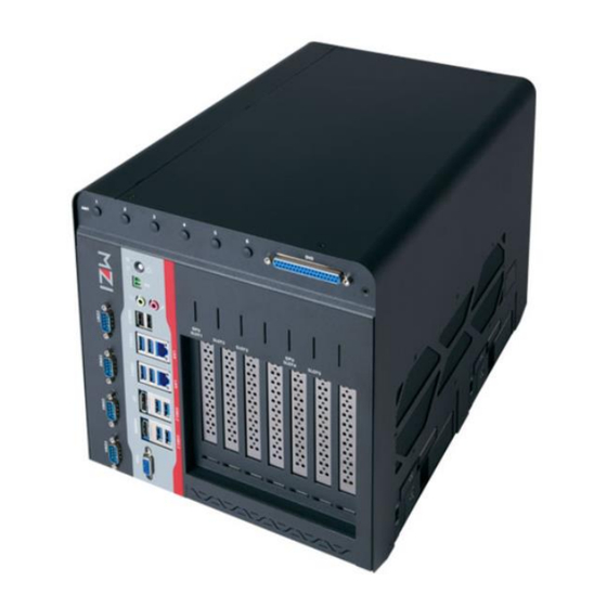
MZ1-10ADP User Manual V1.1 aster Series Embedded System Rugged GPU Computing System Supports Intel® Raptor Lake-S / Alder Lake-S Core-i Processor up to 125W... - Page 2 No part of this document may be reproduced, copied, translated, or transmitted in any form or by any means, electronic or mechanical, for any purpose, without the prior written permission of MiTAC Computing Technology Corporation. All information and specification provided in this manual are for reference only and remain subject to change without prior notice.
- Page 3 Safety Information WARNING! / AVERTISSEMENT! Always completely disconnect the power cord from your chassis whenever you work with the hardware. Do not make connections while the power is on. Sensitive electronic components can be damaged by sudden power surges. Only experienced electronics personnel should open the PC chassis.
- Page 4 Ordering Information Model Number Description MZ1-10ADP-R680E Rugged GPU Computing System with Intel® R680E Chipset and 5 PCIe Slots. 2xDDR5 SO-DIMM 4800Mhz up to 64GB, 1xHDMI, 1xDisplayPort, 1xVGA, 2x2.5G LAN, 4xUSB3.2Gen2, 5xUSB3.2Gen1, 1xUSB2.0, 4xCOM, 5xPCIe slot, 9~48V DC-in. w/o AC adaptor Rugged GPU Computing System with Intel®...
- Page 5 Packing List Q’ty Item Description MZ1-10ADP Rugged GPU Computing System Wall Mount Brackets (2 pcs in 1 set) Screw Pack (For Wall Mount Bracket) 4-pin Terminal Block Power Connector (For DC Power Input) 2-pin Terminal Block Power Connector (For Remote Power Control) GPU card to riser board power cable (3 types, 2 pcs for each type) Optional Xpansion Modules and Accessories Model Number...
-
Page 6: Table Of Contents
CONTENTS PREFACE ............................... 1 CHAPTER 1: INTRODUCTION ........................ 8 1.1 Overview ..........................8 1.2 Product Features ........................9 1.3 CPU Options ......................... 10 1.4 GFX/AI Card Options ......................11 1.5 Hardware Specification ......................12 1.6 Mechanical Specification ..................... 16 1.7 System I/O Placement ......................17 CHAPTER 2: DIP SWITCH SETTING AND PIN DEFINITION .............. - Page 7 INTRODUCTION This chapter provides the MZ1-10ADP Rugged GPU Computing System product overview, including features, hardware and mechanical specifications.
-
Page 8: Chapter 1: Introduction
NVIDIA GFX cards unlocks exceptional parallel computing, reducing latency and dependence on the cloud. With expandability, it caters to evolving edge needs, while its rugged construction ensures reliable operation in harsh environments. By choosing the MiTAC MZ1-10ADP, you empower your edge infrastructure with cutting-edge AI capabilities, faster... -
Page 9: Product Features
1.2 Product Features MZ1-10FEP Rugged GPU Computing System features: 125W Intel 12th Gen Alder Lake-S Core i (Up to SO-DIMM DDR5 x2 (Up to 4800/5600MHz and 64GB) 600W+600W Support Dual high-end GFX cards ( 1500W Power Budget system power consumption ... -
Page 10: Cpu Options
1.3 CPU Options E Core P Core Processor Name Cache Cores Threads TDP Boost Clock Base Clock Base Clock 13th Generation Intel® Raptor Lake-S Intel® Core™ i9-13900 Processor 1.50 GHz 2.00 GHz 5.60 GHz 8 + 16 32 Intel® Core™ i9-13900E Processor 1.30 GHz 1.80 GHz 5.20 GHz 8 + 16 32 Intel®... -
Page 11: Gfx/Ai Card Options
1.4 GFX/AI Card Options Model Name Display Memory CUDA NVIDIA A40 48GB 3 x DP1.4a 48 GB GDDR6 10,752 300W *with optional fan and fan duct kit NVIDIA RTX 6000 Ada Gen. 4 x DP1.4a 24 GB GDDR6 18,176 300W NVIDIA RTX A6000 48GB 4 x DP1.4a 48 GB GDDR6... -
Page 12: Hardware Specification
1.5 Hardware Specification System 13th/12th Gen Intel® Raptor Lake-S/Alder Lake-S Processor Core i9/i7/i5/i3/Celeron/Pentium (Up to 125W) Chipset Intel® R680E 2 x 262-pin SO-DIMM / DDR5 4800/5600* MHz / Max. 64 GB (Non-ECC) Memory Gen Intel Raptor Lake-S Core i9/i7 SKUs can support up to 5600MHz Audio Realtek®... - Page 13 Power/HDD LED Power ON/OFF button 3 x RS232 (support power 5V/12V) 1 x RS232/422/485 (support power 5V/12V) 1 x DB37 connector for 32-bit DIO 1 x HDMI 2.0b 1 x VGA 1 x DisplayPort 1.4 Rear I/O 2 x 2.5G RJ45 LAN Ports 4 x USB3.1 Gen2 4 x USB3.1 Gen1 2 x USB2.0...
- Page 14 Storage -40 ~ 85°C (-40 ~185°F) Temperature Operating 10% ~ 90% R/H (Non-condensing) Humidity Storage Humidity 10% ~ 95% @85°C non-condensing Vibration MIL-STD-810H, Follow Method 514.8C-I Category 4 for Truck Resistance MIL-STD-810H 516.8 procedure I - functional shock, Operating 20G, 11ms Shock Resistance (Follow IEC 60068-2-27 half sine) Certification...
- Page 15 *Note : Please make sure that the power consumption is in the spec of the power supply output capability from AC adaptor (300W or 1000W). Please choose the suitable AC adaptor for your application. AC/DC 24V/12.5A, 300W Terminal Block Power Adaptor AC/DC 48V/9.20.8A, 1000W Power Supply *Note : The safety ambient operating temperature is 40 degree C if the...
-
Page 16: Mechanical Specification
1.6 Mechanical Specification MZ1-10ADP Mechanical Dimension: 264 x 415 x 256mm Maximum Dimension for single GFX card (System Fan put inside): 340 mm x 150 mm x 4 Slots... -
Page 17: System I/O Placement
1.7 System I/O Placement... - Page 18 DIP SWITCH SETTING AND PIN DEFINITION This chapter provides information about how to set up the dip switch and use internal I/Os of MZ1-10ADP Rugged GPU Computing System hardware.
-
Page 19: Chapter 2: Dip Switch Setting And Pin Definition
CHAPTER 2: DIP SWITCH SETTING AND PIN DEFINITION This chapter provides information about how to set up the dip switch, and use internal I/Os of MZ1-10ADP hardware. 2.1 Jumper and Internal Connector Overall Placement 2.1.1 Main Board Top side placement Item Location Interface... - Page 20 2.1.2 Main Board Bottom side placement Item Location Interface PWRBT2 Power button JPWRBT1 Power button at PCB Screw Terminal Block,2P,3.5mm,R/A Audio Jack: MIC IN + LINE OUT I/O USB2.0 x2 I/O USB3.0 x2 + RJ45 2.5G USB3.0 x2 + RJ45 2.5G Display Port I/O USB3.0 x2 high Rise I/O HDMI 1.4 4K 30 Hz...
- Page 21 Item Location Interface Buzzer M2_KB1 M2 key B connector: 1. Pcie x1/ USB3.0/ SATA by DIP switch 2. USB2.0 3. 4G/5G SIM card RTCRST1 Clear CMIS button MINI_PCIE1 Mini_Pcie1: Support Pcie x1/ SATA + SIM card MINI_PCIE2 Mini_Pcie2: Support Pcie x1 + SIM card Me key E connector: Pcie x1, USB2.0 battery CR2032 &...
- Page 22 Item Location Interface Sw_P1_Pw_A COM1 PWR 5V/12V setting 5V = Sw_P1_Pw_A 12V = Sw_P1_Pw_C Sw_P1_Ri_A COM1 PWR/RI setting = SW_P1_RI_A PWR = SW_P1_RI_C Sw_P2_Pw_A COM2 PWR 5V/12V setting 5V = Sw_P2_Pw_A 12V = Sw_P2_Pw_C Sw_P2_Ri_A COM2 PWR/RI setting = SW_P2_RI_A PWR = SW_P2_RI_C Sw_P3_Pw_A COM3 PWR 5V/12V setting...
- Page 23 2.1.3 Riser Board Top side placement Item Location Interface Gxf2_Pw1 Support Pcie Slot #4,#5 EXT PWR connector Gxf2_Pw2 Support Pcie Slot #4,#5 EXT PWR connector Gxf1_Pw1 Support Pcie Slot #1,#2,#3 EXT PWR connector Gxf1_Pw2 Support Pcie Slot #1,#2,#3 EXT PWR connector Btb_1 Support MS-01IGN-S10 Vehicle Power Ignition Card Fan_Sys1...
-
Page 24: Dip Switch Setting
2.2 DIP Switch Setting M2 key B socket Interface at M2_KB1 Slot - Support SATA SSD ( HW settinh by HW DIP switch) - Support Pciex1 SSD ( HW settinh by HW DIP switch) - Support USB3.0 ( HW settinh by HW DIP switch) - Support Pciex1 Gen1/Gen2/Gen3device ( HW settinh by HW DIP switch) - Support USB2.0 device M2B_SW1... - Page 25 Serial Port power DIP switch setting guide Item Location Interface S1 Sw_P1_Pw_A COM1 PWR 5V/12V setting 5V = A 12V = C S2 Sw_P1_Ri_A COM1 PWR/RI setting RI = A PWR = C S3 Sw_P2_Pw_A COM2 PWR 5V/12V setting 5V = A 12V = C S4 Sw_P2_Ri_A...
-
Page 26: Internal Connector Pin Definition
2.3 Internal Connector Pin Definition GPU PWR connector TF-CON;POWER,SBU,ATX,AC/600V,4P*2,MA,4.2mm,ST,LCP,BLACK,TIN,GPU AMPHENOL LTD G874D08E135C2HR FOXCONN (HONG HAI PRECISION IN HMDA040-L2B00-4H 12V_2 GXF2_PW2 4P*2 Support 600W at Gxf1_Pw1 + Gxf1_Pw2 2ea GPU PWR connector Support 600W at Gxf2_Pw1 + Gxf2_Pw2 2ea GPU PWR connector Notes: Don’t support to short 12V_1 + 12V_2 2ea different PWR rail Item Location... - Page 27 PCIe Slot #1~#5 Item Location Interface S1_Pciex16 Slot#1 : CPU Pcie X16 Gen4 or x8 with Slot#4 GXF card S2_Pciex4 Slot#2 : PCH Pcie x4 GEN4 S3_Pciex4 Slot#3 : PCH Pcie x4 GEN4 RA10 S4_Pciex8 Slot#4 : CPU Pcie X8 Gen4 RA11 S5_Pciex1 Slot#5 : PCH Pcie x1 GEN3...
-
Page 28: External Connector Pin Definition
2.4 External Connector Pin Definition DC input power connector at DC_P1 & DC_P2 location V_IN_A input PWR range from +12V~48V 12V max PWR = 600W 48V max PWR = 1500W DC_P1 connector pinout Pin Signal Name 1 V_IN_A 2 V_IN_A 3 V_IN_A 4 CAR_IGN DC_P2 connector pinout... - Page 29 2-pin Terminal Block for Remote Power ON/OFF Signal EXT_PWRBT_ON/OFF Ground 32-bit GPIO in DB37 Pin# DB37 Signal USBM_GPIOA0 USBM_GPIOA1 USBM_GPIOA2 USBM_GPIOA3 USBM_GPIOA4 USBM_GPIOA5 USBM_GPIOA6 USBM_GPIOA7 USBM_GPIOB0 USBM_GPIOB1 USBM_GPIOB2 USBM_GPIOB3 USBM_GPIOB4 USBM_GPIOB5 USBM_GPIOB6...
- Page 30 USBM_GPIOB7 USBM_GPIOC0 USBM_GPIOC1 USBM_GPIOC2 USBM_GPIOC3 USBM_GPIOC4 USBM_GPIOC5 USBM_GPIOC6 USBM_GPIOC7 USBM_GPIOD0 USBM_GPIOD1 USBM_GPIOD2 USBM_GPIOD3 USBM_GPIOD4 USBM_GPIOD5 USBM_GPIOD6 USBM_GPIOD7...
- Page 31 COM#1 / COM#2 / COM#3 / COM#4 PWR RS232 RS232 RS422 RS485 TX- [ RS485 D-(B) TX(B) TX+ [ RS485 D+(A) TX(A) RX+ [ RX(A) RX- [ RX(B) 5V/12V...
-
Page 32: Xpansion Module Ms-01Ign-S10
2.5 Xpansion Module MS-01IGN-S10 This Module MS-01IGN-S10 can detect vehicle ignition status and control the on/off delay time setting. This document is used to guide how to set up this power ignition module correctly. a. Location b. Function Emergency reset button This button is for engineering use only. - Page 33 SYSTEM SETUP This chapter provides information about how to set up the MZ1-10ADP Rugged GPU Computing System hardware installation.
-
Page 34: Chapter 3: System Setup
CHAPTER 3: SYSTEM SETUP This chapter provides information about how to set up the MZ1-10ADP Rugged GPU Computing System hardware installation. 3.1 CPU, Memory, and M.2 M Key Module Installation Please follow the instructions to install CPU & memory as below. Loosen 7 screws to release heatsink front cover Loosen 8 screws for heatsink... - Page 35 Remove black mylar and CPU socket cover, and follow CPU direction to install CPU. Assemble SO-DIMM DDR5 memory to slots...
- Page 36 Assemble M.2 M key/B-M key module to M.2 M key slot...
-
Page 37: B Key/E Key/Mpcie Module Installation
3.2 M.2 B Key/E Key/mPCIe Module Installation Loosen 7 screws, and move chassis cover as below direction Assemble M.2 B key/E key/mPCIe module as below location on the bottom of main board... -
Page 38: Pcie Card Installation
3.3 PCIe Card Installation Loosen 4 screws to release PCIe card holder bracket Loosen 1 screw for PCIe door plate which will be used for expansion card and assemble with PCIe card bracket. Then adjust PCIe card holder to fix the card to resist S&V conditions... -
Page 39: Rtc Battery Maintenance
3.4 RTC Battery Maintenance Preparation for disassembly: Flathead Screwdriver (The battery holder is designed for great vibration resistant and harsh environment use, so it needs to use a tool to disassemble the coin battery) Insert flathead screwdriver to the gap of one side of RTC battery vertically. Rotate the screwdriver at around 45 degrees to loosen the coin battery... -
Page 40: 1000W Psu Cable Assembly
3.5 1000W PSU Cable Assembly - Green, white, and black cables connect to power cords. Red and black cables connect to MZ1 terminal block connectors. - Black cables connect to GND, and red cables connect to V+. - Page 41 BIOS SETUP This chapter provides information about how to set up BIOS and use BIOS menu items to adjust basic function settings.
-
Page 42: Chapter 4: Bios Setup
CHAPTER 4: BIOS SETUP This chapter provides information about how to set up BIOS and use BIOS menu items to adjust basic function settings. 4.1 Main Page Field Name BIOS Vender Default Value American Megatrends Comment This field is not selectable. There is no help text associated with it. Field Name Core Version Default Value... - Page 43 Value ME Firmware Version. Comment This field is not selectable. There is no help text associated with it. Field Name Processor Information Value Display the installed CPU brand. Comment This field is not selectable. There is no help text associated with it. Field Name Microcode Revision Value...
- Page 44 Comment This field is not selectable. There is no help text associated with it. Field Name System Date Default Value [Www mm/dd/yyyy] Possible Value Www : Mon/Tue/Wed/Thu/Fri/Sat/Sun mm : 1-12 dd : 1-31 yyyy : 1900-9999 Help Set the Date. Use Tab to switch between Date elements. Default Ranger: Year : 1900-9999 Months : 1-12 Days : Dependent on month Range of Years may vary.
-
Page 45: Advance Page
4.2 Advance Page Field Name Onboard Device Help Onboard Device Configuration. Comment Press Enter when selected to go into the associated Sub-Menu. Field Name CPU Configuration Help CPU Configuration Parameters. Comment Press Enter when selected to go into the associated Sub-Menu. Field Name VMD setup menu Help... - Page 46 Field Name Network Stack Configuration Help Network Stack Settings. Comment Press Enter when selected to go into the associated Sub-Menu. Field Name NVMe Configuration Help NVMe Device Options Settings Comment Press Enter when selected to go into the associated Sub-Menu.
- Page 47 4.2.1 Onboard Device Field Name Turbo Mode Default Value [Enabled] Possible Value Enabled Disabled Help Enable/Disable processor Turbo Mode (requires EMTTM enabled too).AUTO means enabled. Field Name State After G3 Default Value [S5 State] Possible Value S0 State S5 State Help Specify what state to go to when power is re-applied after a power failure (G3 state).
- Page 48 Default Value [256M] Possible Value 128M 256M Help Select DVMT5.0 Total Graphic Memory size used by the Internal Graphics Device. Field Name HD Audio Default Value [Enabled] Possible Value Enabled Disabled Help Control Detection of the HD-Audio device. Disabled = HDA will be unconditionally disabled Enabled = HDA will be unconditionally enabled.
- Page 49 4.2.2 CPU Configuration Field Name Default Value Displays CPU Signature Comment This field is not selectable. There is no help text associated with it. Field Name Brand String Default Value Displays the CPU brand string Comment This field is not selectable. There is no help text associated with it. Field Name Default Value VMX Supported or Not...
- Page 50 4.2.3 VMD Setup Menu Field Name VMD Configuration Default Value VMD Configuration. Comment This field is not selectable. There is no help text associated with it. Field Name Enable VMD controller Default Value [Disabled] Possible Value Disabled Enabled Help Enable/Disable to VMD controller.
- Page 51 4.2.4 Trusted Computing Field Name Firmware Version Default Value TPM module version. Comment This field is not selectable. There is no help text associated with it. Field Name Vendor Default Value TPM module vendor name. Comment This field is not selectable. There is no help text associated with it. Field Name Security Device Support Default Value...
- Page 52 4.2.5 Super IO Configuration Field Name Serial Port 1 Configuration Help Set Parameters of Serial Port 1 (COMA) Comment Press Enter when selected to go into the associated Sub-Menu. Field Name Serial Port 2 Configuration Help Set Parameters of Serial Port 2 (COMB) Comment Press Enter when selected to go into the associated Sub-Menu.
- Page 53 4.2.5.1 Serial Port 1 Configuration Field Name Serial Port Default Value [Enabled] Possible Value Disabled Enabled Help Enable or Disable Serial Port(COM) Field Name Device Settings Default Value Device Super IO COM1 Address and IRQ. Comment This field is not selectable. There is no help text associated with it. Field Name Change Settings Default Value...
- Page 54 1T/1R RS485 with termination resistor TX ENABLE Low Active Disabled Help Configure serial port as RS232/RS422/RS485. 4.2.5.2 Serial Port 2 Configuration Field Name Serial Port Default Value [Enabled] Possible Value Disabled Enabled Help Enable or Disable Serial Port(COM) Field Name Device Settings Default Value Device Super IO COM2 Address and IRQ.
- Page 55 4.2.5.3 Serial Port 3 Configuration Field Name Serial Port Default Value [Enabled] Possible Value Disabled Enabled Help Enable or Disable Serial Port(COM) Field Name Device Settings Default Value Device Super IO COM3 Address and IRQ. Comment This field is not selectable. There is no help text associated with it. Field Name Change Settings Default Value...
- Page 56 4.2.5.4 Serial Port 4 Configuration Field Name Serial Port Default Value [Enabled] Possible Value Disabled Enabled Help Enable or Disable Serial Port(COM) Field Name Device Settings Default Value Device Super IO COM4 Address and IRQ. Comment This field is not selectable. There is no help text associated with it. Field Name Change Settings Default Value...
- Page 57 4.2.6 Hardware Monitor Type Range CPU Temperature -20 ~ (By Processor Tjmax) °C CPU VR Temperature -20 ~ 120 °C DIMM Temperature -20 ~ 120 °C CPU Fan Speed There are many kinds of the fan could be installed into the system, so we could only set 0 RPM for the failed fan speed, and there is also no System Fan Speed high RPM limitation.
- Page 58 4.2.7 S5 RTC Wake Setting Field Name Wake system from S5 Default Value [Disabled] Possible Value Disabled Fixed Time Help Enable or disable System wake on alarm event. Select FixedTime, system will wake on the hr::min::sec specified. Field Name Wake up hour(Show when Wake system from S5 set to Fixed Time) Default Value Possible Value 0-23...
- Page 59 4.2.8 Network Stack Configuration Field Name Network Stack Default Value [Disabled] Possible Value Disabled Enabled Help Enable/Disable UEFI Network Stack. Field Name IPv4 PXE Support (Available when Network stack Enabled) Default Value [Disabled] Possible Value Disabled Enabled Help Enable/Disable IPv4 PXE boot support. If disabled, IPv4 PXE boot support will not be available.
- Page 60 4.2.9 NVMe Configuration Field Name (Device) Comment Press Enter when selected to go into the associated Sub-Menu.
-
Page 61: Security Page
4.3 Security Page Field Name Administrator Password Help Set Administrator Password Field Name User Password Help Set User Password. Field Name HDD Security drive Help HDD Security Configuration for selected drive Comment Press Enter when selected to go into the associated Sub-Menu. Field Name Secure Boot Help... - Page 62 4.3.1 HDD Security Field Name Set User Password Help Set HDD User Password. *** Advisable to Power Cycle System after Setting Hard Disk Passwords ***.Discard or Save changes option in setup does not have any impact on HDD when password is set or removed. If the 'Set HDD User Password' option is hidden, do power cycle to enable the option again...
- Page 63 4.3.2 Secure Boot Field Name Secure Boot Default Value [Enabled] Possible Value Enabled Disabled Help Secure Boot feature is Active if Secure Boot is Enabled, Platform Key(PK) is enrolled and the System is in User mode. The mode change requires platform reset Field Name Secure Boot Mode Default Value...
- Page 64 Field Name Enter Deployed Mode Help Transition between Deployment and User Modes Comment Transition between Deployment and User Modes Field Name Key Management Help Enables expert users to modify Secure Boot Policy variables without Variable authentication Comment Enables expert users to modify Secure Boot Policy variables without full authentication 4.3.2.1 Key Management Field Name...
- Page 65 Field Name Platform Key (PK) Default Value Size:0, Keys:0, Key source: No Keys Help Enroll Factory Defaults or load certificates from a file: 1.Public Key Certificate: a)EFI_SIGNATURE_LIST b)EFI_CERT_X509 (DER) c)EFI_CERT_RSA2048 (bin) d)EFI_CERT_SHAXXX 2.Authenticated UEFI Variable 3.EFI PE/COFF Image(SHA256) Key Source: Factory,External,Mixed Press Enter when selected to go into the associated Sub-Menu “Key Management”.
- Page 66 Field Name Authorized TimeStamps(dbt) Default Value Size:0, Keys:0, Key source: No Keys Help Enroll Factory Defaults or load certificates from a file: 1.Public Key Certificate: a)EFI_SIGNATURE_LIST b)EFI_CERT_X509 (DER) c)EFI_CERT_RSA2048 (bin) d)EFI_CERT_SHAXXX 2.Authenticated UEFI Variable 3.EFI PE/COFF Image(SHA256) Key Source: Factory,External,Mixed comment Press Enter when selected to go into the associated Sub-Menu.
-
Page 67: Boot Page
4.4 Boot Page Field Name Setup Prompt Timeout Default Value Possible Value 1~65535 Help Number of seconds to wait for setup activation key. 65535(0xFFFF) means indefinite waiting. Field Name Bootup NumLock State Default Value [Off] Possible Value Help Select the keyboard NumLock state Field Name Boot Option #1 Default Value... - Page 68 Field Name Boot Option #3 Default Value [USB CD/DVD] Possible Value USB Floppy, CD/DVD, USB CD/DVD, Hard Disk , USB Key, USB Hard Disk , NVME, Network, Disabled Help Sets the system boot order Field Name Boot Option #4 Default Value [Hard Disk] Possible Value USB Floppy, CD/DVD, USB CD/DVD, Hard Disk , USB Key, USB...
- Page 69 Disk Drives. Comment Press Enter when selected to go into the associated Sub-Menu. Field Name (UEFI) USB Key Drive BBS Priorities Help Specifies the Boot Device Priority sequence from available UEFI USB Key Drives. Comment Press Enter when selected to go into the associated Sub-Menu. Field Name (UEFI) USB Hard Disk Drive BBS Priorities Help...
-
Page 70: Save & Exit Page
4.5 Save & Exit Page Field Name Save Changes and Reset Help Reset the system after saving the changes. Field Name Discard Changes and Reset Help Reset system setup without saving any changes. Field Name Restore Defaults Help Restore/Load Default values for all the setup options. -
Page 71: Event Logs
4.6 Event Logs Field Name Change Smbios Event Log Settings Help Press <Enter> to change the Smbios Event Log configuration. Comment Press Enter when selected to go into the associated Sub-Menu. Field Name View Smbios Event Log Help Press <Enter> to view the Smbios Event Log records. Comment Press Enter when selected to go into the associated Sub-Menu. - Page 72 4.6.1 Change Smbios Event Log Settings Field Name Smbios Event Log Default Value [Enabled] Possible Value Enabled Disabled Help Change this to enable or disable all features of Smbios Event Logging during boot. Field Name Erase Event Log Default Value [No] Possible Value No / Yes, Next reset / Yes, Every reset...
- Page 73 4.6.2 View Smbios Event Log Field Name DATE / TIME / ERROR CODE / SEVERITY / COUNT Default Value MM/DD/YY HH:MM:SS Smbios 0x16 N/A N/A Possible Value By Events. Help By Events.
Need help?
Do you have a question about the Master Series and is the answer not in the manual?
Questions and answers