
Related Manuals for ADTRAN DUAL Nx56/64 1200142L1#


Summary of Contents for ADTRAN DUAL Nx56/64 1200142L1#
- Page 1 Plug-On Board PN 1200159L1 61200142L1-1C August 2000 Dual Nx56/64 Option Module PN 1200142L1#HS USER MANUAL...
- Page 2 Trademark: T-Watch Pro is a registered trademark of ADTRAN. 901 Explorer Boulevard P.O. Box 140000 Huntsville, AL 35814-4000 Phone: (256) 963-8000 © 2000 ADTRAN, Inc. All rights reserved. Printed in USA.
- Page 3 Notes provide additional useful information. Cautions signify information that could prevent service interrup- tion. Warnings provide information that could prevent damage to the equipment or endangerment to human life.
-
Page 4: Warranty And Customer Service
Warranty and Customer Service ADTRAN will replace or repair this product within five (5) years from the date of shipment if it does not meet its published specifications or fails while in service. For detailed warranty, repair and return information See the ADTRAN Equip- ment Warranty and Repair and Return Policy Procedure. -
Page 5: Limited Product Warranty
ALLOW THE EXCLUSION OF IMPLIED WARRANTIES, SO THIS EXCLU- SION MAY NOT APPLY TO CUSTOMER. In no event will ADTRAN or its suppliers be liable to Customer for any inciden- tal, special, punitive, exemplary or consequential damages experienced by either Customer or a third party (including, but not limited to, loss of data or information, loss of profits, or loss of use). -
Page 7: Table Of Contents
CTS, DCD, DSR Options ...1-3 Connector ...1-3 Inband Communication Channel ...1-4 Physical Description ...1-4 Chapter 2. Installation...2-1 Unpack & Inspect ...2-1 ADTRAN Shipments Include ...2-1 Installing the Option Module ...2-2 Placement of the Option Module ...2-2 Power Connection...2-3 Attaching the Plug-On Board...2-3 Wiring...2-4 Power-Up Testing and Initialization...2-5... - Page 8 Table of Contents Chapter 3. Operation...3-1 Overview ...3-1 Front Panel Indicators/Buttons...3-1 Menu Structure ...3-1 Slot ...3-1 Port ...3-2 Dual Nx56/64 V.35 Menus Are All Submenus...3-3 Operation ...3-4 PORT Status ...3-4 Operation ...3-4 Dual NX56/64 Status ... 3-5 DTE DATA/CK ... 3-5 DTE Status ...
- Page 9 Table of Contents Index ... Index-1 61200142L1-1 Dual Nx/56/64 Option Module User Manual...
- Page 10 Table of Contents Dual Nx/56/64 Option Module User Manual 61200142L1-1...
-
Page 11: List Of Figures
List of Figures Figure 1-1. Dual Nx56/64 V.35 Option Module...1-4 Figure 2-1. Installing the Option Module ...2-2 Figure 2-2. Attaching the Plug-On Board ...2-3 Figure 3-1. TSU 100 Main Menu Tree ...3-2 Figure 3-2. Dual Nx56/64 V.35 Menu Tree ...3-3 Figure 3-3. - Page 12 List of Figures Dual Nx/56/64 Option Module User Manual 61200142L1-1...
-
Page 13: List Of Tables
List of Tables Table 2-1. Subminiature D Connection... 2-4 Table 3-1. Normal Mode Operation ... 3-8 Table B-1. 26-Pin Subminiature D to V.35 Winchester Cable ... B-2 61200142L1-1 Dual Nx/56/64 Option Module User Manual xiii... - Page 14 List of Tables Dual Nx/56/64 Option Module User Manual 61200142L1-1...
-
Page 15: Chapter 1. Introduction
Chapter 1 DUAL NX56/64 V.35 OPTION MODULE OVERVIEW DUAL NX56/64 V.35 PLUG-ON BOARD OVERVIEW 61200142L1-1 Dual Nx56/64 Option Module User Manual Introduction The Dual Nx56/64 V.35 option module is one of the op- tion modules available for use with the following ADT- RAN equipment: •... -
Page 16: Dual Nx56/64 V.35 Option Module And Plug-On Board Description
Chapter 1. Introduction Dual Nx56/64 V.35 Option Module and Plug-on Board Description Features of the Dual Nx56/64 V.35 Option Module Interfaces Two cables are included with this product. See Appendix B for a detailed description of these cables. Dual Nx56/64 Option Module User Manual The Dual Nx56/64 V.35 option module operates in the option slot of the TSU/TDU/ESU products, while the plug-on board operates as a plug-on to any option mod-... -
Page 17: Dual Nx56/64 V.35 Option Module Specifications
Dual Nx56/64 V.35 Option Module Specifications 61200142L1-1 Dual Nx56/64 Option Module User Manual • Loopbacks Port (toward the network) DTE (toward the DTE) • Both loopbacks can be invoked locally or remotely (V.54) DTE Interface CCITT V.35 Synchronous Rates 56 kbps to 1.536 Mbps (T1) and 2048 Mbps (E1) in 56K or 64K steps Clock Options Normal, Inverted... -
Page 18: Inband Communication Channel
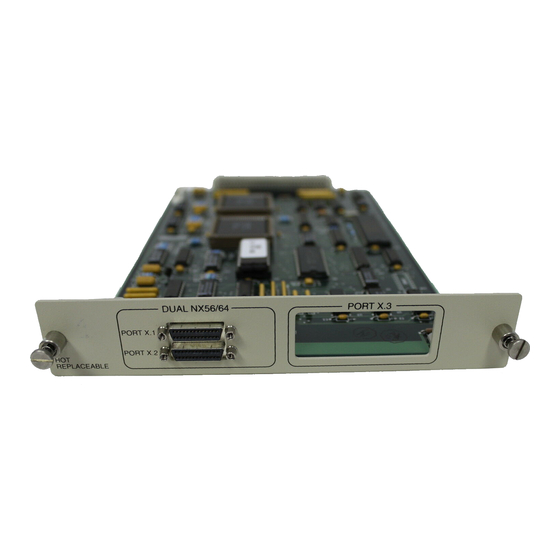
Chapter 1. Introduction Physical Description PORT X.1 DUAL NX 56/64 PORT X.2 1 - Cutout for second V.35 connector 2 - Screw receptacles for plug-on board 3 - Plug-on board header Dual Nx56/64 Option Module User Manual Inband Communication Channel Enabled or Disabled The Dual Nx56/64 V.35 option module plugs into the op- tion slot in the rear of the TSU/TDU/ESU family of prod-... -
Page 19: Chapter 2. Installation
Carefully inspect the option module or plug-on board for any shipping damage. If damage is suspected, file a claim immediately with the carrier and then contact ADTRAN Customer and Product Service (CAPS). If possible, keep the original shipping container for use in shipping the op- tion module or plug-on board back for repair or for veri- fication of damage during shipment. -
Page 20: Installing The Option Module
Chapter 2. Installation INSTALLING THE OPTION MODULE Placement of the Option Module TSU/TDU/ESU UNIT Dual Nx56/64 Option Module User Manual Figure 2-1 shows the proper placement of the option module. Perform the following steps to install the option module: Remove the cover plate from the TSU/TDU/ESU unit rear panel. -
Page 21: Power Connection
Power Connection Attaching the Plug-On Board P O R T X .1 P O R T X .2 61200142L1-1 Dual Nx56/64 Option Module User Manual Each option module derives power from the base TSU/ TDU/ESU unit. Power to the base unit is supplied by a captive eight-foot power cord. -
Page 22: Wiring
Chapter 2. Installation The connection of the header pins between the option module and the plug-on board must be visually verified. An improper connection can cause severe damage to the equipment. Wiring Dual Nx56/64 Option Module User Manual The Dual Nx56/64 option module has two 26-pin sub- miniature D connectors. -
Page 23: Power-Up Testing And Initialization
Power-Up Testing and Initialization 61200142L1-1 Dual Nx56/64 Option Module User Manual The option module executes a self-test during the power- up sequence, as described in the TSU/TDU/ESU manual of the base unit. No initialization input is required. Upon power-up, any previously configured setting for the op- tion module is automatically restored unless the software has changed revision. - Page 24 Chapter 2. Installation Dual Nx56/64 Option Module User Manual 61200142L1-1...
-
Page 25: Chapter 3. Operation
Chapter 3 OVERVIEW Front Panel Indicators/Buttons Menu Structure Slot 61200142L1-1 Dual Nx56/64 Option Module User Manual Operation The Dual Nx56/64 V.35 option module is controlled as part of the TSU/TDU/ESU using the same methods as described in the appropriate TSU/TDU/ESU user manu- Refer to the description of the TSU/TDU/ESU front pan- el indicators and buttons in the appropriate user manual. -
Page 26: Port
Chapter 3. Operation Port 1) STATUS 2) CONFIG 4) MAP IN USE A (B) TSU 100 MAIN MENU 3) UTIL 4)TEST Dual Nx56/64 Option Module User Manual • PORT is the port ID of the V.35 interface to be config- ured. -
Page 27: Dual Nx56/64 V.35 Menus Are All Submenus
Dual Nx56/64 V.35 Menus Are All Submenus DUAL NX56/64 MENU 61200142L1-1 Dual Nx56/64 Option Module User Manual The Dual Nx56/64 V.35 option module menus are access- ed from and operated the same as menus for the TSU 100. Menu items in the main menu in Figure 3-1 on page 3-2 printed in bold italics are submenu choices for Dual Nx56/64 V.35 option modules (see Figure 3-2). -
Page 28: Operation
Chapter 3. Operation Operation PORT Status Operation Dual Nx56/64 Option Module User Manual With the cursor on one of the four main menu choices, press or the number key. This displays the first two Enter submenu items with the cursor on the first item. Use the down arrow key to place the cursor on the desired item;... -
Page 29: Dual Nx56/64 Status
61200142L1-1 Dual Nx56/64 Option Module User Manual The Dual Nx interface offers the status screens listed in this manual. For other option modules, refer to the ap- propriate user manual. Dual NX56/64 Status Select 1.1 NX56/64 DTE DATA/CK DTE STATUS PORT RATE DTE DATA/CK Shows the status (active or not active) of the following... -
Page 30: Port Config
Chapter 3. Operation PORT CONFIG Operation Dual Nx56/64 Option Module User Manual The 7)PORT CONFIG submenu is used for configuration of the Dual Nx56/64 V.35 option module. To display Figure 3-4 on the TSU 100, place the cursor on main menu item 2)CONFIG, and do the following: Press or the number Enter... -
Page 31: Rate 56/64
Chapter 3. Operation Rate 56/64 This sets the base rate of the interface. The actual data rate depends on the number of DS0s assigned to the Nx port. The DTE data rate versus the number of DS0s appear in the DTE Data Rate Chart appendix of the TSU 100 User Manual. -
Page 32: Inhib
Chapter 3. Operation SIGNAL V-54 LOOPBACK Follows — — — — = Do not care Force On = On under all conditions Dual Nx56/64 Option Module User Manual Table 3-1. Normal Mode Operation 511 TEST SELF TEST ACTIVE — 0 INHIB If the Nx interface detects an uninterrupted string of 0s being transmitted toward the network, and if 0s are transmitted for more than one second, then the TSU 100... -
Page 33: Tx Clk Source
TSU 600 A CHAIN IN DSX 1 ROUTER Although a router can accommodate this 8K rate reduction, some DTE devices may not (i.e., video). Determination should be made if the connected DTE can handle this reduced clock source. A second option would be to operate in 56K/DS0. -
Page 34: Factory Restore
The Port Utility submenu is used primarily to access the display of the current software information for each port installed in the unit. This information is required when requesting assistance from ADTRAN Technical Support or when updates are needed. To display Figure 3-6, do the following: Follow the standard operating procedure to access the 3)UTIL menu items. -
Page 35: Run Self-Test
Run Self-Test 61200142L1-1 Dual Nx56/64 Option Module User Manual To display the port name and the software version in- stalled as shown in Figure 3-7, do the following: Use the arrow keys to move through the available ports, or enter the port number with the number key. When the desired port name is displayed, press Enter Press... -
Page 36: Port Test
Chapter 3. Operation Port Test Port Test execution disrupts normal data flow in the port being tested. Operation 1.1 Dual Nx56/64 3-12 Dual Nx56/64 Option Module User Manual This menu item is used to activate testing of specific data ports. It also controls the activation of loopbacks and the initiation of data test patterns. -
Page 37: Rem V.54 Cont
The TSU/TDU/ESU checks the remote loopback activation by detecting a proper response from the remote end. While waiting for the response, the display shows Looping. If successful, the display changes to Looped Up. If unsuccessful, the display shows Failed. 61200142L1-1 Dual Nx56/64 Option Module User Manual REMOTE The remote loopback causes a V.54 code to be sent to the... - Page 38 Chapter 3. Operation 3-14 Dual Nx56/64 Option Module User Manual 61200142L1-1...
-
Page 39: Appendix A. System Messages
Appendix A ALARM MESSAGES Network Interface (NI) 61200142L1-1 Dual Nx56/64 Option Module User Manual System Messages Red Alarm NI unable to align frame with incoming signal Yellow Alarm Remote alarm indication (RAI) being received from the far end Blue Alarm Unframed all 1s (AIS) being received at NI Loss of Signal No signal detected at NI... -
Page 40: Status Messages
Appendix A. System Messages Dual Nx56/64 V.35 Option Module STATUS MESSAGES Network Interface (NI) Dual Nx56/64 Option Module User Manual Clock Slip Difference in frequency of the data clock at the network and DTE PLL Alarm Unable to lock phase lock on the clock provided by the network interface Zeros Alarm All 0s data being sent to the network interface... - Page 41 Dual Nx56/64 V.35 Option Module 61200142L1-1 Dual Nx56/64 Option Module User Manual Loop-Up Data is looped back at both the network interface and the DTE interface of the card Remote Loop Up Sending a V.54 pattern in an attempt to loop up a remote device 511 Pattern On Sending a 511 pattern towards the network interface...
- Page 42 Appendix A. System Messages Dual Nx56/64 Option Module User Manual 61200142L1-1...
- Page 43 26-Pin Subminiature D to Appendix B V.35 Winchester Cable Subminiature D connector should be AMP PN 750850-3 or equivalent. V.35 Winchester cable should be Positronic PNV3400000.70 with GMCT34F0000YR-695 or equivalent. Pins A through NN are V.35 connector pins; pins 101 through 114 are CCITT pins.
-
Page 44: Appendix B. 26-Pin Subminiature D To V.35 Winchester Cable
Appendix B. 26-Pin Subminiature D to V.35 Winchester Cable Table B-1. 26-Pin Subminiature D to V.35 Winchester Cable SUBMINIATURE D PIN & SIGNAL Signal Frame Ground SIGNAL GROUND TD-A TD-B RD-A RD-B ETC-A SIGNAL GROUND TC-A TC-B RC-A RC-B ETC-B Dual Nx56/64 Option Module User Manual V.35 WINCHESTER PIN &... - Page 45 Index Numerics 0 INHIB, port config 3-8 1s Density Protection 1-3 26 Pin Subminiature D (Amp PN 786200-1) to V.35 Winchester, interface 1-2 511 PATT 3-13 511 Pattern Off A-3 511 Pattern On A-3 alarm messages A-1 Attaching the Plug-On Board 2-3 Blue Alarm, network interface A-1 CCITT V.35 electrical, interface 1-2 CCITT V.35 Synchronous, DTE interface 1-3...
- Page 46 Index Payload On, status message A-2 pinouts 2-4 PLL Alarm A-2 port status 3-4 port utility 3-10 Power Connection 2-3 Power On, status message A-2 Power-Up Testing and Initialization 2-5 product overview 1-1 product warranty v PRT/LC 3-12 RATE 56/64, port config 3-7 Red Alarm, network interface A-1 REM V.54 CONT 3-13 REMOTE 3-13...
-
Page 47: Product Support Information
Applications Engineering Sales Post-Sale Support Please contact your local distributor first. If your local distributor cannot help, please contact ADTRAN Technical Support and have the unit serial number avail- able. Technical Support Repair and Return If ADTRAN Technical Support determines that a repair is needed, Technical Sup- port will coordinate with the Customer and Product Service (CaPS) department to issue an RMA number.
Need help?
Do you have a question about the DUAL Nx56/64 1200142L1# and is the answer not in the manual?
Questions and answers