Table of Contents
Advertisement
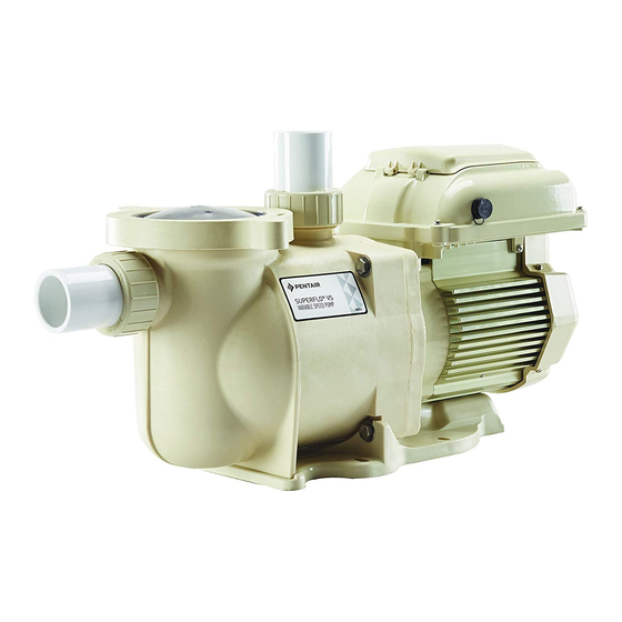
SUPERFLO® VST
SUPERFLO® VS
STA-RITE® SUPERMAX® VS
VARIABLE SPEED PUMPS
IMPORTANT SAFETY INSTRUCTIONS
READ AND FOLLOW ALL INSTRUCTIONS
Translated versions of this manual are available online at / La versión en español de este manual del producto, se
puede encontrar en línea a / La version française de ce manuel est disponible à :
https://www.pentair.com/en/products/pool-spa-equipment/pool-pumps/superflo_vs_variablespeedpump.html
https://www.pentair.com/en/products/pool-spa-equipment/pool-pumps/superflo-vst-pump.html
https://www.pentair.com/en/products/pool-spa-equipment/pool-pumps/supermax_vs_variablespeedpump.html
SAVE THESE INSTRUCTIONS
INSTALLATION AND
USER'S GUIDE
Advertisement
Table of Contents


Need help?
Do you have a question about the SUPERFLO VST and is the answer not in the manual?
Questions and answers
I have a 342001 V/S pump, and occasionally i will run 2 shear decent water falls and it will run fine at 3400 rpm but once it changes speed it just spills out on the pool deck. Is there a way to have it run continuously at 3400 rpm