Pilz PNOZ e4.1p Operating Manual
Hide thumbs
Also See for PNOZ e4.1p:
- Operating instructions manual (12 pages) ,
- Operating instructions manual (12 pages)
Table of Contents
Advertisement
Quick Links
Advertisement
Table of Contents

Related Manuals for Pilz PNOZ e4.1p


Summary of Contents for Pilz PNOZ e4.1p
- Page 1 PNOZ e4.1p Safety relays Operating Manual-21362-EN-05...
- Page 2 Preface This document is a translation of the original document. All rights to this documentation are reserved by Pilz GmbH & Co. KG. Copies may be made for internal purposes. Suggestions and comments for improving this documentation will be gratefully received.
-
Page 3: Table Of Contents
Preparing for operation Supply voltage Input circuit Start circuit Feedback loop Logic connection between several units Logic inputs S35 and S36 Examples Operation Status indicators Faults - malfunctions Dimensions in mm Technical details Safety characteristic data Operating Manual PNOZ e4.1p 21362-EN-05... - Page 4 Contents Remove plug-in terminals Order reference Product Accessories Operating Manual PNOZ e4.1p 21362-EN-05...
-
Page 5: Introduction
PNOZ e4.1p Introduction Validity of documentation This documentation is valid for the product PNOZ e4.1p. It is valid until new documentation is published. This operating manual explains the function and operation, describes the installation and provides guidelines on how to connect the product. -
Page 6: Safety
Safety Intended use The safety relay PNOZ e4.1p provides a safety-related interruption of a safety circuit. The unit meets the requirements of EN ISO 13849-1 up to and including PL d (Cat. 3). The safety mat only partially meets this requirement (see Clause 4.15 of EN ISO 13856-1). -
Page 7: Safety Regulations
In safety-related applications, please comply with the mission time T in the safety-re- lated characteristic data. When decommissioning, please comply with local regulations regarding the disposal of electronic devices (e.g. Electrical and Electronic Equipment Act). Operating Manual PNOZ e4.1p 21362-EN-05... -
Page 8: For Your Safety
The relay meets the following safety requirements: The circuit is redundant with built-in self-monitoring. The safety device remains effective in the case of a component failure. The safety outputs are tested periodically using an off-test. Operating Manual PNOZ e4.1p 21362-EN-05... -
Page 9: Block Diagram/Terminal Configuration
Faults - malfunctions [ 21]). It will not be pos- sible to switch the unit back on until the error has been rectified and the supply voltage has been switched off and then on again. Operating Manual PNOZ e4.1p 21362-EN-05... -
Page 10: Operating Modes
PNOZ e4.1p AND/OR connection The PNOZ e4.1p has two logic inputs S35 (OR) and S36 (AND) for logic connections between several units. Operating modes Automatic reset (start): Unit is active once the safety mat has been cleared. Manual restart (start): Unit is not active until the start button has been operated and then released and the safety mat has not been activated. -
Page 11: Wiring
The power supply must comply with the regulations for extra low voltages with protect- ive electrical separation (SELV, PELV) in accordance with VDE 0100, Part 410. Ensure the wiring and EMC requirements of EN 60204-1 are met. Terminal Y5 is provided for Pilz-internal diagnostic purposes. Operating Manual PNOZ e4.1p 21362-EN-05... -
Page 12: Preparing For Operation
Input circuit AND logic input active logic connection Control of a PSS (safety outputs cannot be used for logic functions) black black black black Control of a logic input or cascading input black black black black Operating Manual PNOZ e4.1p 21362-EN-05... -
Page 13: Start Circuit
Safety mat with start-up test NOTICE With automatic reset (start) The unit starts automatically when the safeguard is reset, e.g. after the safety mat is cleared. Use external circuit measures to prevent an unexpec- ted restart. Operating Manual PNOZ e4.1p 21362-EN-05... -
Page 14: Feedback Loop
Install all the logically linked units in the same control cabinet or ensure that faults re- garding the units' connection are excluded, e.g. via protected installation of the connec- tion cables. All linked units must be connected to the same supply voltage. Operating Manual PNOZ e4.1p 21362-EN-05... -
Page 15: Logic Inputs S35 And S36
The logic inputs are connected to each other as follows: Safety outputs Input circuit Logic inputs S35 and S36 from the PNOZ e4.1p enable additional PNOZelog or PNOZmulti units to be logically AND/OR connected. Input circuit Logic AND + OR con-... - Page 16 PNOZ e4.1p Example 1: Loads are connected to the safety outputs of Unit 1. In addition, a safety output is AND- linked to 4 other PNOZelog units via the logic input S36. Operating Manual PNOZ e4.1p 21362-EN-05...
- Page 17 PNOZ e4.1p Example 2: Loads are connected to the safety outputs of Unit 1. In addition, a safety output is AND- linked to another PNOZelog unit via the logic input S36. Operating Manual PNOZ e4.1p 21362-EN-05...
- Page 18 Unit 4. This means that Unit 4 and Unit 1 can set the outputs on Unit 2 and Unit 3 to low. A short circuit between +24 VDC and a safety output must be excluded! Operating Manual PNOZ e4.1p 21362-EN-05...
- Page 19 Unit 3. If Unit 2 sends a high signal to the OR input on Unit 3, a high signal will be present at the outputs on Unit 3, irrespective of the status of its input circuit. Operating Manual PNOZ e4.1p 21362-EN-05...
-
Page 20: Operation
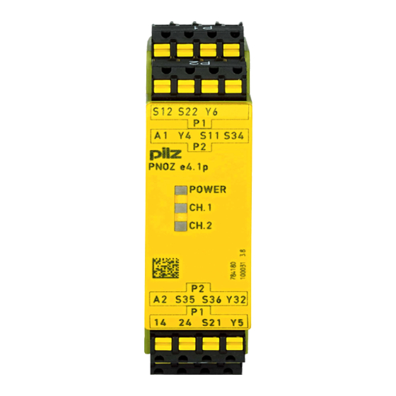
LED flashes Status indicators POWER Supply voltage is present, operating mode is detected. POWER Initialisation phase CH.1 There is a high signal at safety output 14. CH.2 There is a high signal at safety output 24. Operating Manual PNOZ e4.1p 21362-EN-05... -
Page 21: Faults - Malfunctions
LEDs indicate an error and the safety outputs carry a low signal. The plant or machinery driven via the safety outputs will be shut down. The unit can only be restarted when the supply voltage is switched off for at least 1 s and then switched on again. Operating Manual PNOZ e4.1p 21362-EN-05... - Page 22 LED CH.1 or CH.2 flashes 3 times, short Pause Once for one second Pause 3 times, for one second each Error code 1: LED CH.1 or CH.2 flashes 3 times, short Pause Once for one second Operating Manual PNOZ e4.1p 21362-EN-05...
- Page 23 The table below shows the relationship between the number of flashes and the error code. The key to the error codes is described in the Error coding table. Number of flashes Decimal er- ror code Operating Manual PNOZ e4.1p 21362-EN-05...
- Page 24 3x short – 1x long – 13x long – 3x short 1, 4 3x short – 1x long Operating mode changed during Check wiring for the operating mode – 4x long – 3x short operation and rectify fault Operating Manual PNOZ e4.1p 21362-EN-05...
- Page 25 – 3x short puts and +24 VDC 2, 0, 3 3x short – 2x long <19.2 VDC Keep within the supply voltage range – 16x long – 3x long of 19.2 ... 30 VDC – 3x short Operating Manual PNOZ e4.1p 21362-EN-05...
-
Page 26: Dimensions In Mm
Logic input 24 V 24 V Current at Input circuit DC 5 mA 5 mA Start circuit DC 5 mA 5 mA Feedback loop DC 5 mA 5 mA Logic input 5 mA 5 mA Operating Manual PNOZ e4.1p 21362-EN-05... - Page 27 120 ms 120 ms Logic inputs max. 200 ms 200 ms Response time tr semiconductor outputs typ. 40 ms 40 ms max. 43 ms 43 ms Maximum time of feedback loop monitoring 150 ms 150 ms Operating Manual PNOZ e4.1p 21362-EN-05...
- Page 28 PPO UL 94 V0 PPO UL 94 V0 Front ABS UL 94 V0 ABS UL 94 V0 PPO UL 94 V0 PPO UL 94 V0 Connection type Screw terminal Spring-loaded terminal Mounting type plug-in plug-in Operating Manual PNOZ e4.1p 21362-EN-05...
-
Page 29: Safety Characteristic Data
SIL 3 5,82E-05 SC output via safety PL d Cat. 3 SIL CL 2 3,68E-09 SIL 2 6,29E-05 All the units used within a safety function must be considered when calculating the safety characteristic data. Operating Manual PNOZ e4.1p 21362-EN-05... -
Page 30: Operating Manual Pnoz E4.1P
A safety function's SIL/PL values are not identical to the SIL/PL values of the units that are used and may be different. We recommend that you use the PAScal software tool to calculate the safety function's SIL/PL values. Operating Manual PNOZ e4.1p 21362-EN-05... - Page 31 Product type Features Order no. Terminal block filter 1 Terminal block with filter for 3-10 kOhm load range 774 195 Terminal block filter 2 Terminal block with filter for 10-30 kOhm load range 774 196 Operating Manual PNOZ e4.1p 21362-EN-05...
- Page 32 Back cover Support Technical support is available from Pilz round the clock. Americas Australia Scandinavia Brazil +61 3 95600621 +45 74436332 +55 11 97569-2804 Spain Canada Europe +34 938497433 +1 888-315-PILZ (315-7459) Austria Switzerland Mexico +43 1 7986263-0 +41 62 88979-30...
Need help?
Do you have a question about the PNOZ e4.1p and is the answer not in the manual?
Questions and answers