Table of Contents
Advertisement
TABLE OF CONTENTS
Introduction ............................................................................................ 3
Introduction .......................................................................................... 3
Features............................................................................................... 3
Front Panel Controls .............................................................................. 4
Input Gain Control ............................................................................... 4
Input Impedance Control ................................................................. 4-5
Analog Output Control ......................................................................... 5
HPF Control ........................................................................................ 5
Gain Switch ......................................................................................... 5
Phantom Switch ................................................................................... 5
Phase Switch ...................................................................................... 5
Plate Voltage Switch......................................................................... 5-6
Meter Switch........................................................................................ 6
Digital Section Controls ........................................................................ 6
Digital Level Control ............................................................................ 6
Dither Switch ....................................................................................... 6
Sample Rate Control ........................................................................... 7
Optical Switch...................................................................................... 8
Front Panel Connections......................................................................... 8
Instrument Inputs................................................................................. 8
Rear Panel Connections......................................................................... 8
Balanced Inputs................................................................................... 8
Balanced Outputs ............................................................................... 8
Insert Jacks ......................................................................................... 9
Word Clock Jacks................................................................................. 9
ADAT Input .......................................................................................... 9
Optical Output....................................................................................... 9
S/PDIF Output ..................................................................................... 9
AES/EBU Output .................................................................................. 9
Signal Path Flow ................................................................................... 10
Signal Path Flow Diagram .................................................................. 10
Operating Instructions ......................................................................... 10
Obtaining the best noise performance ............................................... 10
Adjusting the input impedance...................................................... 10-11
Obtaining the perfect digital level setting ........................................... 11
Setting the tube plate voltage ............................................................ 11
Warranty Information ........................................................................... 12
Service .................................................................................................. 12
Specifications ....................................................................................... 13
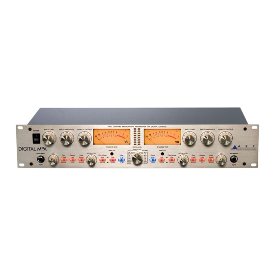
ART Digital MPA™ Microphone Preamplifier
2
Advertisement
Table of Contents

Related Manuals for Art DIGITAL MPA


Summary of Contents for Art DIGITAL MPA
-
Page 1: Table Of Contents
Obtaining the best noise performance ... 10 Adjusting the input impedance... 10-11 Obtaining the perfect digital level setting ... 11 Setting the tube plate voltage ... 11 Warranty Information ... 12 Service ... 12 Specifications ... 13 ART Digital MPA™ Microphone Preamplifier... -
Page 2: Introduction
Pro MPA, ART engineers set out to develop the next generation of professional microphone preamplifier. The Digital MPA is the culmination of years of research and development, and sets a new standard for quality and value. Professional features and spectacular tone are what make the Digital MPA a world-class microphone preamplifier. -
Page 3: Front Panel Controls
ART Digital MPA™ Microphone Preamplifier FRONT PANEL CONTROLS Input Gain Control This control optimizes the input signal level before the tube gain is applied. Both Microphone and Instrument input gains remain the same and are affected by this adjustment. Input gain can be adjusted from 0dB (for line level signals) to 45dB of gain. -
Page 4: Analog Output Control
ART Digital MPA™ Microphone Preamplifier The 1/4” instrument input is NOT affected by this control, and remains high (>1M Ohm) imped- ance. Analog Output control The output signal level at the rear output jacks is adjusted by this control. It can provide from +10dB of gain (fully clockwise) to completely muted. -
Page 5: Plate Voltage Switch
ART Digital MPA™ Microphone Preamplifier control. The DMPA takes about 10-30 seconds to smoothly transition from one mode to the other. There is a slight increase in gain in the “High” plate voltage mode. In the “normal” (OUT) position, the tube distortion gradually rises until it smoothly clips. The tube is run almost completely open-loop in this mode, providing a musical tube “crunch”... -
Page 6: Sample Rate Control
ART Digital MPA™ Microphone Preamplifier Generally, keep the unit in 24-bit mode (the out position of the switch) unless you are connected to a system that will truncate the signal to 16 bits. The 24-bit mode has significantly greater dynamic range. -
Page 7: Optical Switch
ART Digital MPA™ Microphone Preamplifier Optical Switch The optical output jack of the DMPA can have one of two formats. When this switch is depressed AND lit blue, this jack will output 8 channels of ADAT. (ADAT cannot be output if the sample rate exceeds 48KHZ - the Sample Rate selection being set to an internal rate). -
Page 8: Insert Jacks
ART Digital MPA™ Microphone Preamplifier Insert Jacks The insert jacks are used to process the audio passed on to the A/D converter. The Insert Jacks are wired: Tip = Input, Ring = Output, Sleeve = Ground. The input impedance is 10K Ohm and the output impedance is 1K Ohm. -
Page 9: Signal Path Flow
ART Digital MPA™ Microphone Preamplifier SIGNAL PATH FLOW DIAGRAM The signal path of the DMPA consists of a discrete class A microphone pre-amp followed by a Hi Pass Filter, a balanced differential tube circuit with a 20dB Gain switch and then the phase switch. -
Page 10: Obtaining The Perfect Digital Level Setting
ART Digital MPA™ Microphone Preamplifier NOTE: the Input impedance control only affects the cannon connector inputs. The 1/4” instrument input on the front panel is NOT affected by this control in any way. The instrument input impedance is ALWAYS >1M Ohm. -
Page 11: Warranty Information
ART Digital MPA™ Microphone Preamplifier WARRANTY INFORMATION Limited Warranty Applied Research and Technology will provide warranty and service for this unit in accordance with the following warrants: Applied Research and Technology (A R T) warrants to the original purchaser that this product and the components thereof will be free from defects in workmanship and materials for a period of five years from the date of purchase. -
Page 12: Specifications
A/D Dynamic Range ...>115dB “A” weighted (typ.) A/D THD ...<0.001% @1K (typ.) A/D Input Sensitivity...+12dBu min A/D Insert Input Impedance…………………………>10K Ohms The ART Digital MPA™ is ADAT licensed. ART Digital MPA™ Microphone Preamplifier 15Hz to 120 kHz (+0, -1dB) @ high plate voltage...
Need help?
Do you have a question about the DIGITAL MPA and is the answer not in the manual?
Questions and answers